当前位置:网站首页>Frame relay network configuration example learning record
Frame relay network configuration example learning record
2022-07-23 13:00:00 【Amateur visionary】
Frame relay network configuration example
Frame relay (frame relay) Is a public data network communication protocol . Frame relay is an effective data transmission technology , It can transmit digital information quickly and cheaply in one-to-one or one to many applications . It can be used in speech 、 data communication , Can be used for LAN (LAN) It can also be used in Wan (WAN) Communication for . Each frame relay user will get a dedicated line connected to the frame relay node . Frame relay network for end users , It handles data transmission with other users through a constantly changing and invisible channel .
List of articles
1、 The goal of the experiment
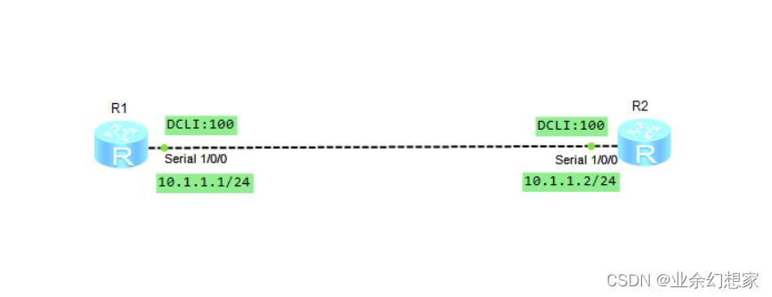
Connect two routers through frame relay protocol IP Layer interworking
2、 Network topology
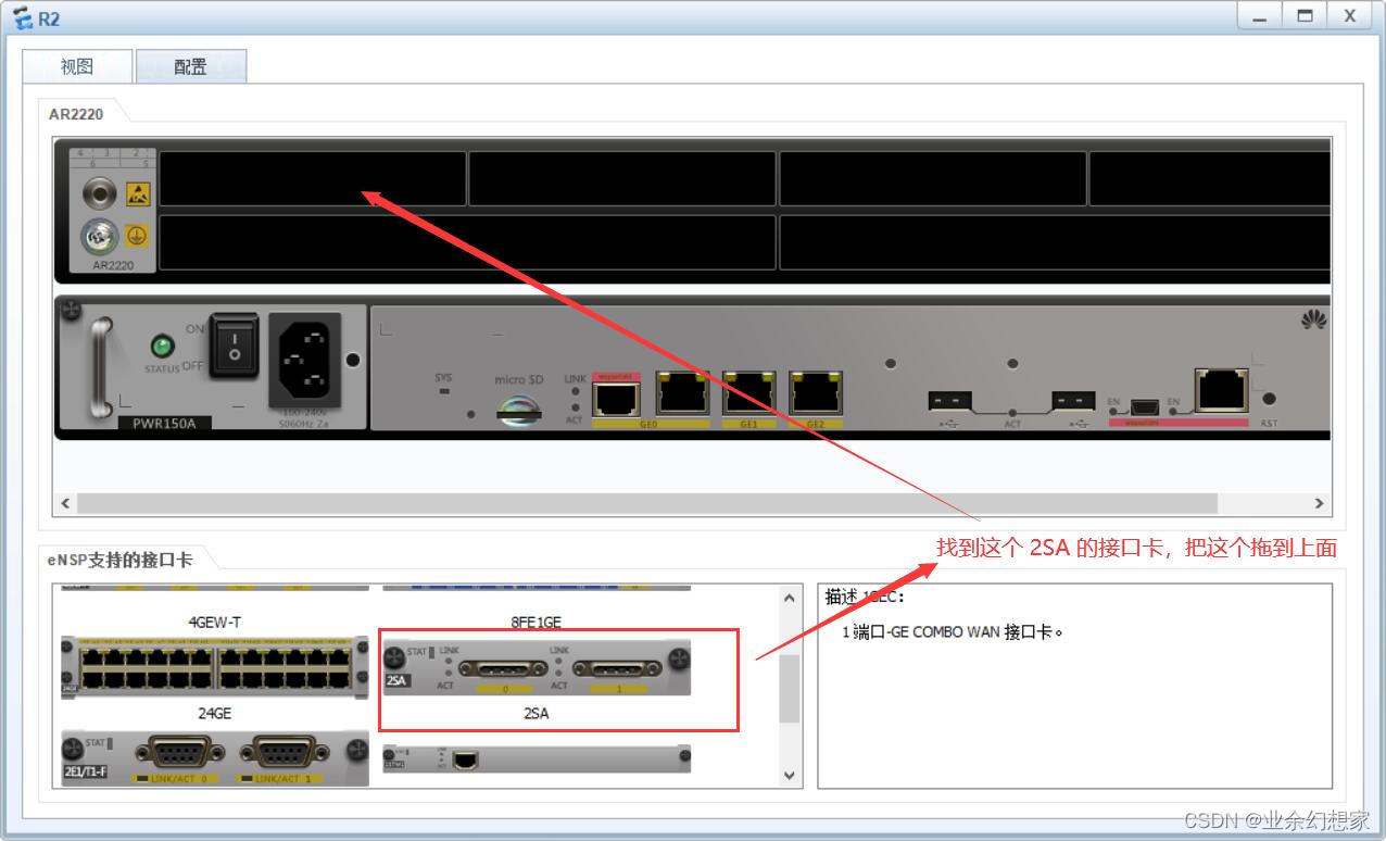
Some routers are not equipped by default Serial Interface , But you can add it manually Serial Interface hardware , First select to add Seria l Interface router , Click on the right , Select Settings , Enter the view , And then put 2SA Pull it into the upper row of holes , Then you can get Serial The interface
notes : Adding an interface card can only be operated when the device is turned off
3、 Configuration steps
(1) Set up the router R1 The port of IP Address and link layer protocol
<Huawei>system-view
[Huawei]sysname R1
[R1]interface Serial1/0/0
[R1-Serial1/0/0]ip address 10.1.1.1 24
[R1-Serial1/0/0]link-protocol fr  // Configure the port encapsulation type as frame relay protocol link protocol
[R1-Serial1/0/0]fr interface-type dte  // The configuration port type is  DTE
[R1-Serial1/0/0]fr dlci 100  // Configure local  DLCI  Number
[R1-fr-dlci-Serial1/0/0-100]quit

// If the peer router supports reverse address resolution , Then configure address dynamic mapping , Otherwise, configure static address mapping , The order is as follows :
[R1-Serial1/0/0]fr inarp  // Configure dynamic address mapping
[R1-Serial1/0/0]fr map ip 10.1.1.2 100  // Configure static address mapping
[R1-Serial1/0/0]quit
(2) Set up the router R2 The port of IP Address and link layer protocol
<Huawei>system-view
[Huawei]sysname R2
[R2]interface Serial1/0/0
[R2-Serial1/0/0]ip address 10.1.1.2 24
[R2-Serial1/0/0]link-protocol fr
[R2-Serial1/0/0]fr interface-type dce
[R2-Serial1/0/0]fr dlci 100  // Configure local  DLCI  Number
[R2-fr-dlci-Serial1/0/0-100]quit

// If the peer router supports reverse address resolution , Then configure address dynamic mapping , Otherwise, configure static address mapping , The order is as follows :
[R2-Serial1/0/0]fr inarp  // Configure dynamic address mapping
[R2-Serial1/0/0]fr map ip 10.1.1.1 100  // Configure static address mapping
[R2-Serial1/0/0]quit
4、 test
(1) In the router R2 View frame relay mapping information on
The frame relay protocol port is mapped to the opposite end through the address DLCI, That is, both parties can communicate .
[R2]display fr map-info
Map Statistics for interface Serial1/0/0 (DCE)
  DLCI = 100, IP 10.1.1.1, Serial1/0/0
    create time = 2022/07/21 18:25:00, status = ACTIVE
    encapsulation = ietf, vlink = 2
(2) stay R1 On can ping through R2 Port address of , It indicates that the link layer frame relay works normally
[R1]ping 10.1.1.2
  PING 10.1.1.2: 56  data bytes, press CTRL_C to break
    Reply from 10.1.1.2: bytes=56 Sequence=1 ttl=255 time=60 ms
    Reply from 10.1.1.2: bytes=56 Sequence=2 ttl=255 time=20 ms
    Reply from 10.1.1.2: bytes=56 Sequence=3 ttl=255 time=10 ms
    Reply from 10.1.1.2: bytes=56 Sequence=4 ttl=255 time=30 ms
    Reply from 10.1.1.2: bytes=56 Sequence=5 ttl=255 time=30 ms

  --- 10.1.1.2 ping statistics ---
    5 packet(s) transmitted
    5 packet(s) received
    0.00% packet loss
    round-trip min/avg/max = 10/30/60 ms
5、 Summary
The main characteristics of frame relay :
User information in frames (frame) Transmit for unit , In the process of transmission, the network changes the frame structure 、 Check transmission errors , Discard the error frame directly , meanwhile , By comparing the address segment in the frame DLCI The identification of , Realize statistical reuse of user information .
Virtual circuit for frame relay network (Virtual Circuit,VC) To connect the frame relay devices at both ends of the network , Each virtual circuit is connected with a data link identifier (Data Link Connection Identifier,DCLI) Define the frame relay connection channel .
Frame relay network provides the ability of data communication between user equipment , Its equipment can be divided into data terminal equipment (Data Terminal Equipment,DTE) And data communication devices (Data Communication Equipment,DCE),DCE Is used to DTE Access network .
Frame relay network interface is divided into user network interface (User Network Interface,UNI) Interface with the network (Network Network Interface,NNI),UNI finger DTE and DCE Interface between ,NNI finger DCE and DCE Port between .
If there are mistakes in the article , Welcome to criticize and correct
边栏推荐
- Secret key remote login server to realize secret free login
- Hcip --- condition matching and OSPF Protocol
- How to write a web page with a common text editor
- App compilation and packaging deployment manual
- RK3588编译问题集
- Sword finger offer summary
- Nas里搭建Frpc客户端【超级无脑】
- 2020-09-22
- jenkins部署
- PDF Online preview, use of pdf.js
猜你喜欢

Eth-Trunk 配置实例学习记录

C #: TOPK: take the largest 100 before 10000 numbers, and sort the heap

FTP experiment and overview

Unity3d:ugui, UI and special effect particle level, bakemesh above 2018.2, particles between two images and in Scrollview

单臂路由配置实例学习记录
Single arm routing configuration instance learning record

Hcip - first experiment
zabbix监控详细安装到部署

路由与交换技术——静态路由

Learning diary - (routing and switching technology) DHCP (Dynamic Host Configuration Protocol)
随机推荐
Write a test case where the executable depends on.So
Array leetcode977. Square of ordered array
Integer times integer overflow
Gameframework: resource hot code analysis, check version information, download version files, verify version files, get the number of updated files, download files, taskpool
Hcip --- mGRE comprehensive experiment
openvpn部署
Learning diary - (routing and switching technology) OSPF Protocol
查询交叉编译出的可执行文件依赖库
C output Fibonacci sequence
C language can also write Plants vs. Zombies
NFS service deployment notes
Analysis ideas of strong consistency and weak consistency and concurrency skills of distributed scenarios
sftp部署配置
单臂路由配置实例学习记录
0 double pointer leetcode844. Compare strings with backspace
Hcip - HDLC and PPP protocols
Gameframework:resource loading, resource loading, dependency loading, task pool, object pool, reference count
Unity3d:assetbundle simulation loading, synchronous loading, asynchronous loading, dependent package loading, automatic labeling, AB browser, incremental packaging
Summary of basic SQL operations
C # enter a letter and judge its case