当前位置:网站首页>STM32 (VIII) -- PWM output
STM32 (VIII) -- PWM output
2022-06-23 18:37:00 【Domineering ocean】
PWM Output
introduction
We are in the daily embedded development ,PWM It can be said that it is one of the most commonly used technologies . We are driving by electric motor 、 Voltage control 、 From measurement 、 Communication to many fields of power control and conversion ,PWM Has an extremely important position .
Introduce
PWM brief introduction
PWM Pulse width modulation (PWM), It's English “Pulse Width Modulation” Abbreviation , Short for pulse width modulation , It is a very effective technology to control analog circuit by using digital output of microprocessor . A little bit more simple , It's the control of pulse width . It's a digital coding method for analog signal level . Through the use of high resolution counter , A specific square wave is used to modulate the duty cycle of the signal .PWM The signal is still digital , Because at any given moment , Full amplitude DC power supply either has (ON), Or nothing at all (OFF). The source of voltage or current is in the form of a current (ON) Or break (OFF) The repetitive pulse sequence is added to the analog load . When it is on, that is when the DC power supply is added to the load , When the power is cut off, it is when the power is cut off . As long as the bandwidth is enough , Any analog value can be used PWM Encoding .
STM32 Of PWM
STM32 In addition to TIM6 and 7. Other timers can be used to generate PWM Output . One of the advanced timers TIM1 and TIM8 It can produce as many as 7 On the road PWM Output . And universal timers can also generate up to 4 On the road PWM Output , such ,STM32 At most... Can be generated at the same time 30 road PWM Output !
The pulse width modulation mode can produce a pulse width modulated by TIMx_ARR The register determines the frequency 、 from TIMx_CCRx The register determines the duty cycle signal .
stay TIMx_CCMRx In register OCxM Bit write ’110’(PWM Pattern 1) or ’111’(PWM Pattern 2), Be able to set each... Independently OCx The output channel generates a circuit PWM. Must be set by TIMx_CCMRx The register of OCxPE Bit enables the corresponding preload register , Finally, set TIMx_CR1 The register of ARPE position ,( In count up or centrosymmetric mode ) Preload register that enables automatic reload .
Only when an update event occurs , The preloaded register can be transferred to the shadow register , So before the counter starts counting , Must be set by TIMx_EGR In register UG Bit to initialize all registers .
OCx The polarity of can be determined by software in TIMx_CCER In register CCxP Bit settings , It can be set to high level active or low level active .OCx The output of enables you to pass (TIMx_CCER and TIMx_BDTR In storage )CCxE、CCxNE、MOE、OSSI and OSSR Bit combination control .
Capture / Compare mode register (TIMx_CCMR1/2)
This register has 2 individual ,TIMx _CCMR1 and TIMx _CCMR2.TIMx_CCMR1 control CH1 and 2, and TIMx_CCMR2 control CH3 and 4.
Channel available for input ( Capture mode ) Or output ( Comparison mode ), The direction of the channel is determined by the corresponding CCxS Definition . The functions of other bits of this register are different in input and output modes .OCxx Describes the function of the channel in the output mode ,ICxx Describes the function of the channel in the output mode . So we must pay attention to , The functions of the same bit in output mode and input mode are different .

What we need to explain here is the mode setting bit OCxM, This part is made up of 3 A composition .
A total of... Can be configured 7 Patterns , We use PWM Pattern , So this 3 Bit must be set to 110/111. These two kinds of PWM The difference between modes is that the polarity of the output level is opposite .
Capture / Compare enable register (TIMx_CCER)

This register is relatively simple , We only use CC2E position , This bit is an input / Capture 2 Output enable bit , If you want to PWM from IO output , This bit must be set to 1, So we need to set this bit to 1.
Capture / Compare register (TIMx_CCR1~4)

This register has 4 individual , Corresponding 4 Channels CH1~4. Because of this 4 Each register is about the same , We just use TIMx_CCR1 As an example to introduce . In output mode , The value of this register is the same as CNT Value comparison of , Generate corresponding actions according to the comparison results . Take advantage of this , By modifying the value of this register , You can control PWM The output pulse width of .
ARR For automatic reloading of registers ,CCR For capture / Compare register ,CNT It is the counter of the timer ,CNT From 0 Began to increase , Use PWM After the model , The effective level can be set , as well as PWM The pattern of . The figure above shows when CNT The value is less than CCRx when , Output low level , When CNT The value is greater than CCRx when , The output high point is flat , So we can change ARR To change PWM The cycle of , change CCRx To change PWM Duty cycle of , So as to achieve any frequency and any duty cycle PWM wave .
Software implementation
STM32F103C8 Yes 15 individual PWM Pins and 10 individual ADC Pin . It has 16 position PWM The resolution of the (2^16).
therefore 65535 The value of is 100% Duty cycle , Average voltage = Total voltage ;
Again ,32767 The value of is 50% Duty cycle , Average voltage =50% Total voltage ;
13107 The value of is 20% Duty cycle , Average voltage =20% Total voltage .
PWM The related functions are set in the library function file stm32f10x_tim.h and stm32f10x_tim.c
In file .
TIM3 PWM Partial initialization
//PWM Output initialization
//arr: Auto reload value
//psc: Clock presplitting frequency
void TIM3_PWM_Init(u16 arr,u16 psc)
{

	GPIO_InitTypeDef GPIO_InitStructure;
	TIM_TimeBaseInitTypeDef  TIM_TimeBaseStructure;
	TIM_OCInitTypeDef  TIM_OCInitStructure;


	RCC_APB1PeriphClockCmd(RCC_APB1Periph_TIM3, ENABLE);	// Enable timer 3 The clock
 	RCC_APB2PeriphClockCmd(RCC_APB2Periph_GPIOB  | RCC_APB2Periph_AFIO, ENABLE);  // Can make GPIO Peripherals and AFIO Multiplexing function module clock

	GPIO_PinRemapConfig(GPIO_PartialRemap_TIM3, ENABLE); //Timer3 Partial remapping  TIM3_CH2->PB5

   // Set this pin to multiplex output function , Output TIM3 CH2 Of PWM Pulse shape  GPIOB.5
	GPIO_InitStructure.GPIO_Pin = GPIO_Pin_5; //TIM_CH2
	GPIO_InitStructure.GPIO_Mode = GPIO_Mode_AF_PP;  // Multiplexing push pull output
	GPIO_InitStructure.GPIO_Speed = GPIO_Speed_50MHz;
	GPIO_Init(GPIOB, &GPIO_InitStructure);// initialization GPIO

   // initialization TIM3
	TIM_TimeBaseStructure.TIM_Period = arr; // Set the value of the auto reload register cycle for the next update event load activity
	TIM_TimeBaseStructure.TIM_Prescaler =psc; // Set as TIMx Prescaled value of clock frequency divisor
	TIM_TimeBaseStructure.TIM_ClockDivision = 0; // Set the clock split :TDTS = Tck_tim
	TIM_TimeBaseStructure.TIM_CounterMode = TIM_CounterMode_Up;  //TIM Upcount mode
	TIM_TimeBaseInit(TIM3, &TIM_TimeBaseStructure); // according to TIM_TimeBaseInitStruct The parameter specified in TIMx Unit of time base

	// initialization TIM3 Channel2 PWM Pattern
	TIM_OCInitStructure.TIM_OCMode = TIM_OCMode_PWM2; // Select timer mode :TIM Pulse width modulation mode 2
 	TIM_OCInitStructure.TIM_OutputState = TIM_OutputState_Enable; // Compare output enable
	TIM_OCInitStructure.TIM_OCPolarity = TIM_OCPolarity_High; // Output polarity :TIM High output polarity
	TIM_OC2Init(TIM3, &TIM_OCInitStructure);  // according to T The specified parameter initializes the peripheral TIM3 OC2

	TIM_OC2PreloadConfig(TIM3, TIM_OCPreload_Enable);  // Can make TIM3 stay CCR2 Pre loaded registers on

	TIM_Cmd(TIM3, ENABLE);  // Can make TIM3


}
modify TIM3_CCR2 To control the duty cycle .
Here is the configuration function
void TIM_SetCompare2(TIM_TypeDef* TIMx, uint16_t Compare2)
{

  /* Check the parameters */
  assert_param(IS_TIM_LIST6_PERIPH(TIMx));
  /* Set the Capture Compare2 Register value */
  TIMx->CCR2 = Compare2;
}
When you use it , We just need to call it directly .
Application routines
 int main(void)
 {

 	u16 PWMValue=0;
	int i=0;
	delay_init();	    	 // Delay function initialization
	NVIC_PriorityGroupConfig(NVIC_PriorityGroup_2); 	 // Set up NVIC Interrupt grouping 2:2 Bit preemption priority ,2 Bit response priority
	uart_init(115200);	 // The serial port is initialized to 115200
 	LED_Init();			     //LED Port initialization
 	TIM3_PWM_Init(899,0);	 // Regardless of the frequency .PWM frequency =72000000/900=80Khz
   	while(1)
	{


 		delay_ms(10);
 		if(i>666)
 		{

		PWMValue=0;
		i=0;
		}
		else
		{

		PWMValue++;
		i++;
		}
		TIM_SetCompare2(TIM3,PWMValue);
	}
 }
We will PWMValue This value is set to PWM It's worth , That is, through PWMValue To control PWM Duty cycle of , Then control PWMValue From 0 Change to 666, And then back to 0, So circular , The voltage value will also change .
follow-up
If you want to learn more about the Internet of things 、 Smart home project knowledge , Can pay attention to my Project practice Columns and Combination of hardware and software special column .
Welcome to official account for more information .
It's not easy to write , Thank you for your support .
边栏推荐
- Shell脚本编写
- 【华中科技大学】考研初试复试资料分享
- leetcode刷题:哈希表07 (三数之和)
- Five star certification! Know that Chuangyu has passed the evaluation of the content audit service system of China Academy of Communications
- [sword finger offer] 46 Translate numbers into strings
- leetcode刷题:哈希表03 (快乐数)
- 杰理之无缝循环播放【篇】
- Redis Cluster
- 第十三届蓝桥杯单片机国赛真题
- 微机原理第六章笔记整理
猜你喜欢
![[failure announcement] there is a problem with the redis that replaces memcached, causing the website to fail](/img/b5/447faaee6d5d2d88927e84e17403ed.png)
[failure announcement] there is a problem with the redis that replaces memcached, causing the website to fail

Redis cluster

【華中科技大學】考研初試複試資料分享
Stepping mode of research control motor
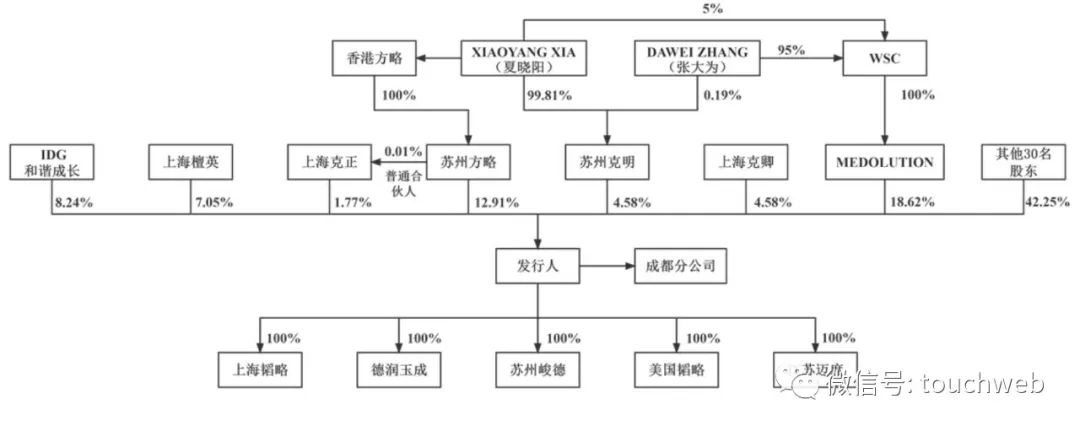
韬略生物冲刺科创板:年亏损过亿 实控人张大为夫妇为美国籍

科技互动沙盘是凭借什么收获人气的

Talk about row storage and column storage of database

leetcode刷题:哈希表02 (两个数组的交集)

可编程的,协议独立的软件交换机(论文阅读)
Leetcode: hash table 06 (ransom letter)
随机推荐
学习编程只需要这三条建议!
VirtP4笔记
为什么要创建公开的OKR?
科技互动沙盘是凭借什么收获人气的
『忘了再学』Shell流程控制 — 39、特殊流程控制语句
一,数组--滑动窗口问题--长度最小的子数组--水果成篮问题
[QT] multiple choice questions
leetcode刷题:哈希表02 (两个数组的交集)
Rancher2.6全新Monitoring快速入门
[failure announcement] there is a problem with the redis that replaces memcached, causing the website to fail
Sword finger offer II 092 Flip character / Sword finger offer II 093 Longest Fibonacci sequence
高级计网笔记(六)
Leetcode 1218. Longest definite difference subsequence (providing an idea)
Shunted Self-Attention | 源于 PvT又高于PvT,解决小目标问题的ViT方法
可编程全功能速率限制器设计硬件交换机
QT实现基于规则的机器翻译系统 课程论文+任务书+项目源码
1、 Array -- sliding window problem -- subarray with the smallest length -- fruit basket problem
Why create a public OKR?
Rancher2.6 new monitoring QuickStart
Leetcode: hash table 04 (sum of two numbers)