当前位置:网站首页>Basic knowledge of trigger (Part 2)
Basic knowledge of trigger (Part 2)
2022-07-24 02:55:00 【Li Yuchen】


Welcome to learn digital circuit ——D trigger .
Here we will explain D Triggers and integration edges D trigger 74LS74, I hope that through our study, you will better understand the mystery of digital circuits .
Catalog
1.D The circuit composition and logic function of the trigger
(1) Circuit structure and graphical symbols
(1) Pin arrangement and graphical symbols
Two 、 Trigger knowledge dry goods
One 、D trigger
1.D The circuit composition and logic function of the trigger
(1) Circuit structure and graphical symbols
As shown in the figure :

In sync RS Based on the trigger , NAND gate G3 Output  Receive the NAND gate G4 The input of R, send R=, Thus avoiding =
 =0 The situation of . And will NAND gate G3 Of S End changed to D Input end , That is to say D trigger .
(2) logic function
D A trigger has only one input , Eliminate the indefinite state of the output .D The trigger has a set 0、 Set up 1 The logical function of , As shown in the figure :

It can be seen from the picture that ,
stay CP=0 period :
NAND gate G3、G4 By CP The low level of the terminal is off , Disable the input signal ,==1, basic RS The trigger remains in its original state .
stay CP=1 period :
① Set up 0 function
When D=0 when , NAND gate G3 Output =1、G4 Output =0, Basically RS The trigger output is set to 0.
② Set up 1 function
When D=1 when , NAND gate G3 Output =0、G4 Output =1, Basically RS The trigger output is set to 1.
As shown in the figure :

In the 3 individual CP During pulse action , because D The change of causes the state of the trigger to change many times , There is somersault , send CP The pulse loses the meaning of synchronization . So in practice , Often use edges D trigger .
Next, let's learn the last trigger : Integrated edge D trigger .
2. Integrated edge D trigger
(1) Pin arrangement and graphical symbols
74LS74 The chip is Integrated double rising edge D trigger , As shown in the figure :
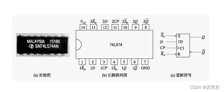
CP It is the clock input ;D For data input ;Q、 Complementary output ;
 It is the direct reset end , Low level active ;
 It is the direct setting end , Low level active ; and Used to set the initial state .
(2) logic function
As shown in the table , Is the integrated double rising edge D trigger 74LS74 My menu , In the table “↑” Indicates that the rising edge triggers .

、 It is often used as the initial state of setting trigger . Integrate D The logic function of the trigger is the same as that described above D Triggers are basically the same , The difference is that it only CP Working at the rising edge .
Two 、 Trigger knowledge dry goods
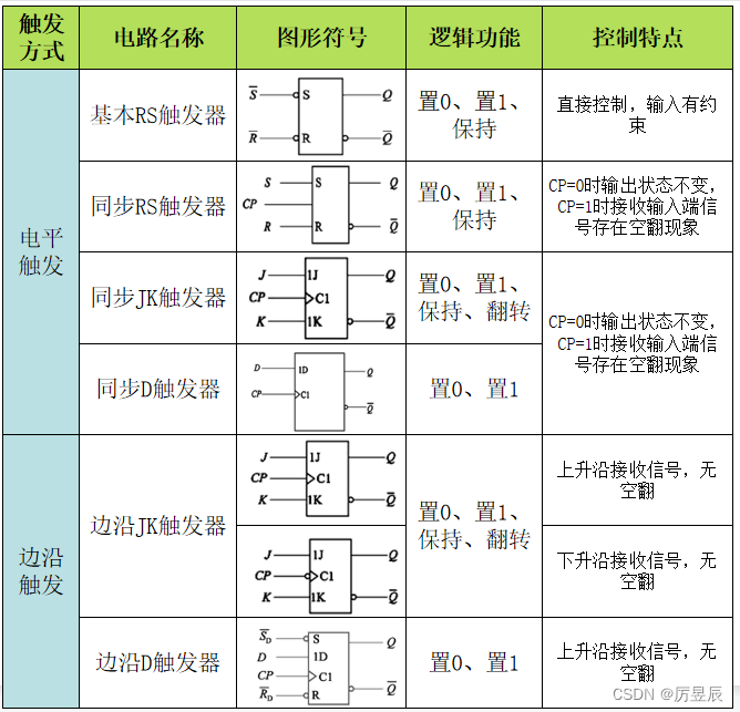
That's all for the trigger , In the next issue, we will continue to explain the sequential logic circuit !🥰🥰
边栏推荐
猜你喜欢
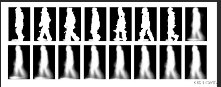
How to get gait energy map Gei

String.split()最详细源码解读及注意事项
![SSM based blog system [with background management]](/img/6b/6a488f5d6926de07c8b1b365362ff6.png)
SSM based blog system [with background management]

动态规划-01背包问题

The simple use of ADB command combined with monkey is super detailed

Audio processing based on time-frequency diagram matlab
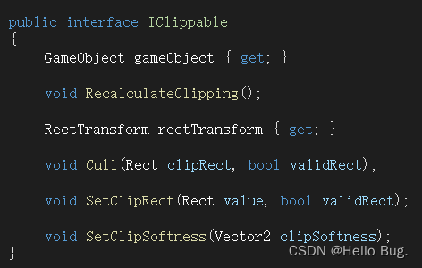
Ugui source code analysis - iclippable

攻防世界WEB练习区(weak_auth、simple_php、xff_referer)

软考---程序设计语言基础(上)
![js傳參時傳入 string有數據;傳入 number時沒有數據;2[0]是對的!number類型數據可以取下標](/img/4e/3d0c25d9579b6d5c00473048dbbd83.png)
js傳參時傳入 string有數據;傳入 number時沒有數據;2[0]是對的!number類型數據可以取下標
随机推荐
An introductory example of structure and combinatorial ideas in go language
[interview: concurrent Article 21: multithreading: activeness] deadlock, livelock, hunger
【AMC】联邦量化
X Actual combat - Cloud Server
The implementation in unity determines whether missing or null
TCP data transmission and performance
Is it safe for qiniu to open an account? Is the Commission of 30000 reliable?
Audio processing based on time-frequency diagram matlab
Doodle icons - a free commercial graffiti style icon library, cute, light and unique
微信公众号在线客服接入发方法和功能详解
Recorded on July 21, 2022
Why use the well architected framework?
Jparepository extension interface
Wonderful! The description of meituan Octo distributed service management system is too clear
Nirvana rebirth! Byte Daniel recommends a large distributed manual, and the Phoenix architecture makes you become a God in fire
自定义kindeditor富文本默认的宽高
C language actual combat guessing game
The process of solving a bug at work
Nodejs builds cloud native microservice applications based on dapr, a quick start guide from 0 to 1
Recommendation system topic | recommendation system architecture and single domain cross domain recall model