当前位置:网站首页>Chapter V online logic analyzer signaltap
Chapter V online logic analyzer signaltap
2022-06-29 06:29:00 【da..】
List of articles
The fifth chapter Online logic analyzer -SIGNALTAP
ps: Simulation reality pc End simulation , and fpga It doesn't matter at all , and signaltap It is the signal of direct feedback chip .
Conduct FPGA In the process of development , Simulation verification will be carried out before the logic code is run on the board , and EDA Simulation tools ( Such as Modelsim etc. ) The use of can make engineers discover some mistakes in the project in advance . However, this does not mean that the design verified by the simulation tool can meet the expectations . in fact , You may still encounter various problems when running on the board . Designed when using simulation tools for verification Testbench The excitation input of sometimes can not cover all possible situations , And there are always subtle differences between software simulation and actual hardware , For such reasons, engineers will still find various design problems when running on the board . And in many cases , stay FPGA Some signals need to be checked during real-time operation , Therefore, a real-time signal analysis tool is needed FPGA Internal real-time signal for debugging and analysis ——SignalTap II emerge as the times require .
SignalTap By Altera The company developed an online 、 Tools for on-chip signal analysis , For design developer verification . Its function is similar to that of a digital logic analyzer , utilize signaltap The tool can basically replace the digital logic analyzer .Signaltap yes Quartus The most commonly used tool in , I hope you can use it skillfully .
The first 1 section Software principle
In the use of SignalTap Let's first understand SignalTap Principle , This helps to understand the parameters .
Pictured 1.5- 1 by SignalTap II How it works , Trigger conditions can be understood intuitively through this diagram 、 Sampling clock 、 The concept of sampling depth, etc ( See Section III for the concept and related settings ) And the relationship between them .
In the course of debugging , Some signals that need to be observed and analyzed are called “ The measured signal ”, There can be multiple measured signals .
SignalTap II The basic working process is as follows : Take the measured signal as the object , Set reasonable triggering conditions as required , In the trigger condition ( As shown in the figure, the falling edge of the measured signal ) A period of time before and after satisfaction , The rising edge of each sampling clock will collect the measured signal once , And the collected signal value is stored in the internal RAM in . The engineer can specify how many samples are taken before and after the trigger condition , If RAM The larger , You can save more data . conversely , If RAM The relatively small , So the data saved is naturally less ,RAM Size determines the amount of observation data . Last SignalTap Will read RAM And display the data in the display one by one , therefore SignalTap The observations are ideal ( This means that when there are some special signals , You can't detect it ), No burr signal , Engineers can observe signals in a display , So as to achieve the purpose of on-line debugging and analysis of the signal .
The first 2 section software interface
open Quartus Software , In the menu bar , choice Tools>SignalTal II Logic Analyzer After that, you can open SignalTap Tools . Here's the picture 1.5:

chart 1.5- 3 Mark the places that need to be noted , Next, we will introduce the functions in detail :
chart 1.5- 3 As identified in 1—4 Configure the basic hardware and software :
1 Select... For the download line ;
2 Detect for hardware ( Identify relevant FPGA equipment );
3 Select... For the project profile (sof file );
4 To load sof file (1-3 After all, you can load the file ).
Icon 5—7 Set... For sampling :
5 Select the sampling clock for , The sampling clock shall be set according to specific needs , It can be the working clock of the module , It can also be an internal signal ;
6 Set... For sampling depth , The greater the sampling depth, the better , It should be reasonably set according to the analysis needs ;
7 Select... For the trigger position , Including the front trigger 、 Intermediate trigger 、 There are three ways for the backend to trigger , Take trigger point as reference , According to the different trigger positions, the signal values in different time periods can be obtained .
The area on the left of the figure 8—9 Set... For the signal , Including adding signals , Set signal trigger conditions, etc . stay 8 Double click in the blank space to add the signal interface , Add corresponding signals in the project as required , After adding a signal, you can set its trigger condition .
Identified in the figure 10 Indicate for resource usage , If there are more resources than FPGA Its own resources , An error will be reported during synthesis, which makes it impossible to analyze .
Uppermost 11 Operation button for running , After starting operation , The waveform will be displayed after the trigger conditions are met .
The first 3 section Usage flow
First, you need to select the download line mode 、FPGA Chip model 、 Project configuration file , Here's the picture 1.5- 4 Shown :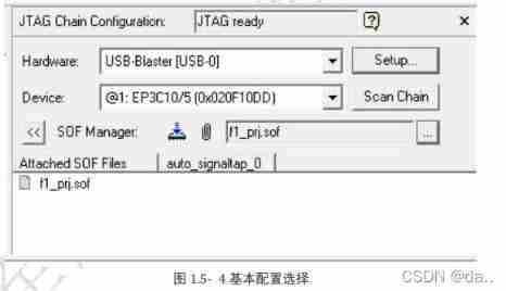
Then set the sampling clock 、 Sampling depth and sampling signal . chart 1.5- 5 Set the sampling clock and sampling depth . Choose... Here FPGA Inside pll PLL output signal c1 As a sampling clock . What needs to be noted here is , The sampling clock is not necessarily the clock in the project , Any internal signal can be used as a sampling clock . Here, the sampling depth is set to 128, That is, a total of 128 Data from two sampling points . stay setup Double click the blank space in the window , Pop up as shown below 1.5- 6 The interface shown here .

chart 1.5- 6 The red box in the middle indicates which phase of the signal is selected , For example, the signal before or after synthesis is selected . Because the software will automatically optimize when integrating , Some signals may not be found . I usually choose pre-synthesis or Design Entry(all name) Pattern , stay Nodes Found Select the signal to be observed , Add it to the right border .
In this case, choose key_col and rst_n Signal to observe , Pictured 1.5-7 Shown :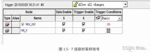
After the sampling signal is selected, the trigger conditions can be set . Observe trigger Conditions A column of ,key_col The default value is xh( Bus type signal don’t care),rst_n The default value is don’t care. stay trigger Conditions Right click in a column rst_n Where the line is , There will be 6 Three trigger conditions are available for the engineer to select .

chart 1.5- 8 in 6 The meanings of these trigger conditions are as follows :
Don’t Care: Show no concern for , That is, any , The value of this signal does not affect the trigger condition ;
Low : Low level trigger ;
Falling Edge: Falling edge trigger ;
Rising Edge: Rising edge trigger ;
High: High level trigger ;
Either Edge: Double edge trigger , That is, trigger when there is a change .
Here, it can be assumed that the rising edge triggers , Yes key_col Also set trigger conditions , The specific settings are as follows . chart 1.5- 9 The meaning of the trigger condition set in is : When rst_n Is the rising edge and key_col All are high (Fh) Trigger when . Be careful , The default value between multiple trigger conditions here is “ And ” The relationship between , May be mistaken for “ or ” The relationship between . Finally, it is integrated and downloaded , Click on “Run Analysis” Button to view the results .
If the trigger condition is true , Then you can Data The sampling waveform is observed in the window , chart 1.5- 10 It is the sampling result of a certain project , It can be seen that the sampling waveform is similar to modelsim The waveforms are similar . Click the waveform to enlarge the waveform for viewing , Right click the waveform to reduce the waveform .
The first 4 section Case description
Several cases will be used in this section to illustrate SignalTap Detailed description of the use steps of .
Case study 1:SignalTap The sampling clock of is not necessarily a clock signal , It can also be any other signal .SignalTap The signal value will be captured at the rising edge of the sampling clock , If there is no rising edge of the clock, then SignalTap Waiting all the time .
Case study 2: During observation, the sampling depth can be changed to observe the value of the signal for a longer time . chart 1.5- 11 The depth set in is 128, This means that a total of 128 The value of a point . If this observation is not enough, you can set it to a larger value .
But it should be noted that ,SignalTap Need to be used FPGA Inside RAM Resource to save the sampled data , So the greater the sampling depth , To be used RAM The greater the , Occupied at the same time FPGA More resources . However FPGA Our resources are limited , When FPGA The internal resource of does not support setting the number of sampling points RAM Number of resources , An error message will appear during compilation .

Case study 3: By setting segmented The parameter can check the number of times the trigger condition is met . for example , When the key is found to be out of order , To locate this problem, you need to check the number of key presses , Determine whether it is consistent with the number of captured signals .
The main settings for this operation are as follows :
- take segmented Set to 32;
- The signal will be captured key_vld Pull to the display window , The signal is 1 Indicates that a key is captured .
- Set the trigger condition to :key_vld The rising edge of ;
- Press down run key , Wait until the trigger condition is met ;
- Press the button 4 Time .
- Press the stop snap key .
If at this time SignalTap The waveform interface appears 5 A window , The top 4 Indicates that the conditions are met and that key_vld The rising edge of triggers the condition window , It means that the number of keystrokes pressed is consistent with the captured number . Otherwise, an error occurs , There is a problem with the key .
Case study 4: After adding the signal , If the signal in the interface is displayed in red , Pictured 1.5- 12 Shown , It indicates that there is a problem in the capture of the signal .
The sampling signal is red. The possible reasons for this problem are :
The signal is optimized during circuit synthesis .
a) Although the signal has been generated , But it is not called as a condition , Or not an output signal . At this time, the system considers the signal redundant , Therefore, the signal will be optimized during synthesis .
b) If the signal is a useful signal , Should not be optimized . It means that the circuit has BUG, Engineers are required to locate the error .Combinational logic signals are generally not captured . The solution is to ignore the signal , All the conditions that generate the signal can be called , So as to determine whether the result is correct .
Case study 5: chart 1.5- 13 A case trigger condition included in is : When en Is the falling edge and en_tmp change . Be careful , The trigger will be triggered only when the two conditions are met at the rising edge of the sampling clock .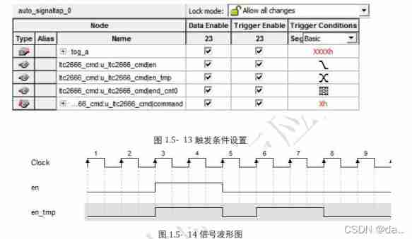
chart 1.5- 14 In the waveform shown , In the 5 Observed at the rising edge of the clock en be equal to 1,en_tmp be equal to 1, It does not meet the conditions . In the first 6 Clock time capture en The falling edge of ( For before 1, For now 0) And en_tmp The falling edge of ( For before 1, For now 0), You can see the 6 Clocks meet the trigger conditions .
The on-line logic analyzer is for each FPGA Learn the basic tools that developers must master , It's using FPGA One of the essential abilities of . in the light of SignalTap How to use , The following links provide 6 A training project to facilitate the practice of mastering this tool .
Engineering training website : Please click on
The first 5 section 6 Engineering cases
5.1 Case study 1
5.2 Case study 2
5.3 Case study 3
5.4 Case study 4
5.5 Case study 5
5.6 Case study 6
边栏推荐
- 力扣每日一题-第30天-1281.整数的各位积和之差
- Week 10 - task 1- fill in the blank: line class inherits point class
- 2-nitro-5,10,15,20-tetra (3,5-dimethoxyphenyl) porphyrin (no2tdmpp) H2) /5,10,15,20-tetra (4-methylphenyl) porphyrin (TMPP) H2) Qiyue porphyrin products
- 64 commonly used terms for data analysis, really all!
- What is 'EC2-Other' filter in 'Cost Explorer' dashboard mean? [closed]
- Why are keys unordered in golang map
- 3 frequently tested SQL data analysis questions (including data and code)
- Programming specification and variables of shell script
- Clickhouse data type
- Agile invincible event
猜你喜欢

2022.02.14 - 239. A single element in an ordered array

Creation of Arduino uno development environment

Meta metauniverse female safety problems occur frequently. How to solve the relevant problems in the metauniverse?
![[C language series] - branch and loop statements](/img/bf/656c9189b4ab4387c5acab1c4a2804.jpg)
[C language series] - branch and loop statements
![Meso tetra (4-N, N, n-trimethylaminophenyl) porphyrin (ttmapp) /meso tetra - [4- (BOC threonine) aminophenyl] porphyrin (TAPP thr BOC) supplied by Qiyue](/img/a9/0869c4f39a96cff63d1e310292c46d.jpg)
Meso tetra (4-N, N, n-trimethylaminophenyl) porphyrin (ttmapp) /meso tetra - [4- (BOC threonine) aminophenyl] porphyrin (TAPP thr BOC) supplied by Qiyue

Fault: ntfrs warning log for id13562

2-nitro-5,10,15,20-tetra (3,5-dimethoxyphenyl) porphyrin (no2tdmpp) H2) /5,10,15,20-tetra (4-methylphenyl) porphyrin (TMPP) H2) Qiyue porphyrin products
![ASP. Net core 6 framework unveiling example demonstration [03]:dapr initial experience](/img/fd/4c24e10fc91a7ce7e709a0874ba675.jpg)
ASP. Net core 6 framework unveiling example demonstration [03]:dapr initial experience
Plugin

Small program large screen adaptation Guide
随机推荐
[high concurrency] deeply analyze the callable interface
Week 12 - task 2- shoulder to shoulder cadres
JDBC | Chapter 5: closing and releasing JDBC connection resources
Week 10 - task 1- fill in the blank: line class inherits point class
It turns out that the joys and sorrows of programmers are not interlinked
2,5-di (3,4-dicarboxyphenoxy) - 4 '- phenylethynylbiphenyldianhydride (pephqda) / Qiyue custom supply porphyrin modified amphiphilic block copolymer peg113-pcl46-porphyrin
Ghost in the Log4Shell
Fault: NetBt log for id4321
Hyperledger Fabric 2. X custom smart contract
AIRNET notes 1
2022-01 Microsoft vulnerability notification
Functions and arrays of shell scripts
Fresnel diffraction with rectangular aperture based on MATLAB
Meso tetra (4-N, N, n-trimethylaminophenyl) porphyrin (ttmapp) /meso tetra - [4- (BOC threonine) aminophenyl] porphyrin (TAPP thr BOC) supplied by Qiyue
National Defense University project summary
Venn diagram proportional and color shading with semi transparency
Analysis comp122 the Caesar cipher
Use of sed in shell script
CodeIgniter active record not equal - CodeIgniter active record not equal
Awk of shell script