当前位置:网站首页>Three layer architecture + routing experiment
Three layer architecture + routing experiment
2022-06-25 22:43:00 【Attiude】
One 、 polymerization
The gateway acts as the central exit of a broadcast domain ; The root bridge of the spanning tree is also the center of a tree , It is also the gathering point of traffic ;
If the two are allocated to different devices, it will lead to a waste of network communication resources , Therefore, it is strongly recommended that they be on the same aggregation layer equipment ;
If based vlan Or group based STP Protocol to work in a three-tier architecture , Will lead to vlan During inter group or inter group communication, the link bandwidth between aggregation layers is required to be high , Can pass Ethernet channel channel (cisco ) Ethernet relay Eth-Trunk( Huawei ) Technology to solve
Channel technology integrates multiple interface logic into one interface , Realize the function of bandwidth superposition ;
Configuration requirements :
1、 The opposite end of the channel must be the same equipment ;
2、 All physical interfaces of the channel should have the same rate 、 Duplex mode ; The same type , same vlan Allow list ;
Three layer channel : All physical links that become channels must first be layer 3 interfaces ; The significance of this is to configure multiple required ip The interface logic of the address is an interface , To configure a ip address
Two 、 management vlan;
The physical interface of layer 2 switch is normal and cannot be configured ip Address ; So there is a SVI( Exchange virtual interfaces ) Interface ;
This interface can be configured ip Address , Factory presence MAC Address ; Used to log in to the device remotely ; The interface defaults to vlan1 in , so vlan1 It is called default management vlan;
There is only one layer 2 switch svi, Default in vlan1 in , Transfer to other vlan when , Previous vlanif The interface will be closed automatically ;
The layer 3 switch supports multiple switches SVI Interface , be-all svi Can coexist ;
[Huawei]interface Vlanif 2
[Huawei-Vlanif2]ip address 192.168.2.1 24
If other network segment devices need to access svi, Then the switch must define the gateway address , Or default route , Otherwise, you can't reply ;
[Huawei]ip route-static 0.0.0.0 0.0.0.0 192.168.2.254
3、 ... and 、 Three layer switch
The ordinary layer-2 switch has the function of layer-3 router equipment ; The standard 3 Layer switches do not have nat function ; It can only be used as a convergence layer device , Unable to become a core layer Internet connected device ;
By default ,cisco All physical interfaces with Huawei's layer 3 switches are layer 2 interfaces ;
The interface of layer 3 switch can be modified to layer 3 function ;
Four 、 Gateway redundancy
VRRP: Virtual routing redundancy protocol – The public agreement , The principle is the same as HSRP Agreement
difference :1、 Multiple devices 2、 only master send out hello 3、 You can use a physical interface ip Address to the gateway address 4、 Preemption is enabled by default 5、hold time 3s
VRRP There can be more than one in a group 3 Floor equipment , There is one. master And multiple backup
A virtual... Is generated normally IP( Can be a real interface ip) And a virtual MAC
The default for each 1s To test master Whether the activity 224.0.0.18 TTL=1 hold time 3s
Election rules :
Priority first , Default 100, Big advantage ; Re interface ip Address Dayou ;
** characteristic :** Fast switching speed ; Can make the gateway IP and MAC The address doesn't have to change ; Gateway switching is transparent to the host ;
Uplink tracking can be implemented
In gateway redundancy technology ,ICMP Redirection is invalid ; Therefore, when uplink DOWN when , The gateway will not switch ;
Uplink tracking can be defined ----- This configuration must take effect when preemption is enabled , And the priority difference between the two devices is less than the down value ; If there are multiple uplink or downlink links in the local area , It is recommended that the sum of the down values during uplink tracking configuration is greater than the priority difference ---- All uplink are full down when , Before the backup device preempts ; Most of the downlink down when , You can let backup devices preempt ;
To configure :
** notes :** Normally, in three-tier architecture, due to the existence of spanning tree , The way of load sharing will vary vlan The location of the root bridge is different , Some links are blocked , Make the load sharing become a burden instead ; Therefore, it is only recommended to use the router directly as the gateway , To use load sharing ;
The experimental requirements :

The topology :

The experimental steps :
1、 Determine the configuration order of the switching layer :channel—> vlan—> Trunk----> STP---->SVI----->VRRP----->DHCP
2、 Binding interface 、 establish vlan
[sw1]int Eth-Trunk 0
[sw1-GigabitEthernet0/0/1]eth-trunk 0
[sw1-GigabitEthernet0/0/1]int g0/0/2
[sw1-GigabitEthernet0/0/2]eth-trunk  0

[sw2]int Eth-Trunk 0
[sw2-GigabitEthernet0/0/1]eth-trunk 0
[sw2-GigabitEthernet0/0/1]int g0/0/2
[sw2-GigabitEthernet0/0/2]eth-trunk  0
 Set the interface type :
[sw1]vlan 2
[sw1]port-group group-member GigabitEthernet 0/0/3  to g0/0/4 Eth-Trunk 0
[sw1-port-group]port link-type trunk
[sw1-GigabitEthernet0/0/3]port link-type trunk
[sw1-GigabitEthernet0/0/4]port link-type trunk
[sw1-Eth-Trunk0]port link-type trunk
[sw1-port-group]port trunk allow-pass vlan 1 2
[sw1-GigabitEthernet0/0/3]port trunk allow-pass vlan 1 2
[sw1-GigabitEthernet0/0/4]port trunk allow-pass vlan 1 2
[sw1-Eth-Trunk0]port trunk allow-pass vlan 1 2

[sw2]vlan 2
[sw2]port-group group-member GigabitEthernet 0/0/3  to g0/0/4 Eth-Trunk 0
[sw2-port-group]port link-type trunk
[sw2-GigabitEthernet0/0/3]port link-type trunk
[sw2-GigabitEthernet0/0/4]port link-type trunk
[sw2-Eth-Trunk0]port link-type trunk
[sw2-port-group]port trunk allow-pass vlan 1 2
[sw2-GigabitEthernet0/0/3]port trunk allow-pass vlan 1 2
[sw2-GigabitEthernet0/0/4]port trunk allow-pass vlan 1 2
[sw2-Eth-Trunk0]port trunk allow-pass vlan 1 2

[sw3]vlan 2
[sw3-Ethernet0/0/1]port link-type trunk
[sw3-Ethernet0/0/1]port trunk pvid vlan 2
[sw3-Ethernet0/0/2]port link-type trunk
[sw3-Ethernet0/0/2]port trunk allo-pass vlan 1 to 2
[sw3-Ethernet0/0/2]int e0/0/4
[sw3-Ethernet0/0/4]port link-type access
[sw3-Ethernet0/0/4]port default vlan 2

[sw4]vlan 2
[sw4-Ethernet0/0/1]port link-type trunk
[sw4-Ethernet0/0/1]port trunk pvid vlan 2
[sw4-Ethernet0/0/2]port link-type trunk
[sw4-Ethernet0/0/2]port trunk allo-pass vlan 1 to 2
[sw4-Ethernet0/0/2]int e0/0/4
[sw4-Ethernet0/0/4]port link-type access
[sw4-Ethernet0/0/4]port default vlan 2
To configure MSTP
[sw1]stp mode mstp
[sw1]stp region-configuration
[sw1-mst-region]region-name a
[sw1-mst-region]instance 1 vlan 1
[sw1-mst-region]instance 2 vlan 2
[sw1-mst-region]active region-configuration

[sw2]stp mode mstp
[sw2]stp region-configuration
[sw2-mst-region]region-name a
[sw2-mst-region]instance 1 vlan 1
[sw2-mst-region]instance 2 vlan 2
[sw2-mst-region]active region-configuration

[sw3]stp mode mstp
[sw3]stp region-configuration
[sw3-mst-region]region-name a
[sw3-mst-region]instance 1 vlan 1
[sw3-mst-region]instance 2 vlan 2
[sw3-mst-region]active region-configuration

[sw4]stp mode mstp
[sw4]stp region-configuration
[sw4-mst-region]region-name a
[sw4-mst-region]instance 1 vlan 1
[sw4-mst-region]instance 2 vlan 2
[sw4-mst-region]active region-configuration
Set group root
[sw1]stp instance 1 root primary
[sw1]stp instance 2 root secondary

[sw2]stp instance 1 root secondary
[sw2]stp instance 2 root primary
Set the edge interface :
[sw3]port-group group-member Ethernet 0/0/3 to e0/0/4
[sw3-port-group]stp edged-port enable
[sw3-Ethernet0/0/3]stp edged-port enable
[sw3-Ethernet0/0/4]stp edged-port enable

[sw4]port-group group-member Ethernet 0/0/3 to e0/0/4
[sw4-port-group]stp edged-port enable
[sw4-Ethernet0/0/3]stp edged-port enable
[sw4-Ethernet0/0/4]stp edged-port enable
Configure the root switch and configure it IP Address
[sw1-Vlanif1]dis this
#
interface Vlanif1
 ip address 172.16.1.1 255.255.255.128
 vrrp vrid 1 virtual-ip 172.16.1.126
 vrrp vrid 1 priority 101
 vrrp vrid 1 track interface GigabitEthernet0/0/5 reduced 2

[sw1-Vlanif1]int vlan 2
[sw1-Vlanif2]dis this
#
interface Vlanif2
 ip address 172.16.1.129 255.255.255.128
 vrrp vrid 1 virtual-ip 172.16.1.254
 dhcp select global
#
return


[sw2-Vlanif1]dis this
#
interface Vlanif1
 ip address 172.16.1.2 255.255.255.128
 vrrp vrid 1 virtual-ip 172.16.1.126
#
return
[sw2-Vlanif1]int vlan 2
[sw2-Vlanif2]dis this
#
interface Vlanif2
 ip address 172.16.1.130 255.255.255.128
 vrrp vrid 1 virtual-ip 172.16.1.254
 vrrp vrid 1 priority 101
 vrrp vrid 1 track interface GigabitEthernet0/0/5
#
return
To configure DHCP( stay SW1 and SW2 Configure on )
DHCP enable
ip pool v1
 gateway-list 172.16.1.126
 network 172.16.1.0 mask 255.255.255.128
 dns-list 114.114.114.114 8.8.8.8

ip pool v2
 gateway-list 172.16.1.254
 network 172.16.1.128 mask 255.255.255.128
 dns-list 114.114.114.114 8.8.8.8
Run through the intranet through dynamic routing :
[sw1-ospf-1]dis this
#
ospf 1 router-id 1.1.1.11
 silent-interface all
 undo silent-interface GigabitEthernet0/0/5
 undo silent-interface Eth-Trunk0
 undo silent-interface Vlanif1
 undo silent-interface Vlanif99
 area 0.0.0.0
  network 172.16.0.2 0.0.0.0
 area 0.0.0.1
  abr-summary 172.16.1.0 255.255.255.0
  network 172.16.1.1 0.0.0.0
  network 172.16.1.129 0.0.0.0
#
return

[sw2-ospf-1]dis this
#
ospf 1 router-id 1.1.1.11
 silent-interface all
 undo silent-interface GigabitEthernet0/0/5
 undo silent-interface Eth-Trunk0
 undo silent-interface Vlanif1
 undo silent-interface Vlanif99
 area 0.0.0.0
  network 172.16.0.6 0.0.0.0
 area 0.0.0.1
  abr-summary 172.16.1.0 255.255.255.0
  network 172.16.1.2 0.0.0.0
  network 172.16.1.130 0.0.0.0
#
return

[r1-ospf-1]dis this
[V200R003C00]
#
ospf 1 router-id 1.1.1.1
 area 0.0.0.0
  network 172.16.0.0 0.0.255.255
#
return

[sw1]ip route-static 172.16.1.0 255.255.255.0 NULL 0
[sw2]ip route-static 172.16.1.0 255.255.255.0 NULL 0
Distribution network :
[r1]ip route-static 0.0.0.0 0 12.1.1.2
[r1]ospf 1
[r1-ospf-1]default-route-advertise
[r1]acl 2000
[r1-acl-basic-2000]rule permit source 172.16.0.0 0.0.255.255
[r1-acl-basic-2000]int g0/0/2
[r1-GigabitEthernet0/0/2]nat outbound 2000
The last step — test :
Test four sets PCping Extranet :
PC1
PC2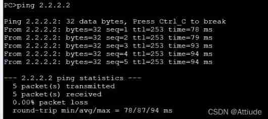
PC3
PC4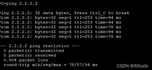
边栏推荐
- China bed and mattress market status research analysis and development prospect forecast report (2022)
- 2022-2028 global proton exchange membrane hydrogen electrolyzer industry survey and trend analysis report
- 【WPF】CAD工程图纸转WPF可直接使用的xaml代码技巧
- Dialog+: Audio dialogue enhancement technology based on deep learning
- Simple and easy-to-use cache library gcache
- Will neuvector be the next popular cloud native security artifact?
- Analysis of China's tractor manufacturing and operation situation and forecast report of prospect trend 2022-2028
- 2022giao考游记
- Adaptive streaming playback statistics set
- Data annotation in the second half: growth flywheel under PLG mode Manfu Technology
猜你喜欢

Simple and easy-to-use cache library gcache

Obsidian基础教程
Will neuvector be the next popular cloud native security artifact?

Privatization lightweight continuous integration deployment scheme -- 03 deployment of Web services (Part 2)

Sqlmap learning (sqli labs as an example)

Tiger Dao VC products are officially launched, a powerful supplement to seektiger ecology
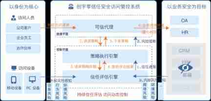
Zero Trust: break the passive development mode of "attack and defense" and build a "moat" for enterprise safety
![[WPF] XAML code skills that can be directly used for converting CAD engineering drawings to WPF](/img/50/bb9e73cb4eabcef4bee8f6d5b2fcb6.png)
[WPF] XAML code skills that can be directly used for converting CAD engineering drawings to WPF

2022-2028 global TFT touch screen industry research and trend analysis report
2022-2028 global co extrusion production line industry research and trend analysis report

随机推荐
Why is BeanUtils not recommended?
This 110 year old "longevity" enterprise has been planning for the next century
Nacos 源码分析01 代码结构
Online crudhasone Association query reports an error unabletouseinternalvariable:list
MySQL Chapter 15 lock
2022-2028 global industrial touch screen industry research and trend analysis report
Programmer weekly (issue 4): the wealth view of programmers
2022-2028 global DC linear variable differential transformer (LVDT) industry survey and trend analysis report
Market depth analysis and development strategy consulting report of China's fire equipment market 2022-2028
How to use the find command
2022-2028 global transmission type photoelectric circuit breaker industry research and trend analysis report
Touring band: a 5g based multi camera remote distributed video production experiment
3.4 cloning and host time synchronization of VMware virtual machine
In depth analysis of Flink fine-grained resource management
Obsidian basic tutorial
Research and Analysis on the current situation of China's magnetic detector Market and forecast report on its development prospect (2022)
[proteus simulation] Arduino uno+ key controls 2-bit digital tube countdown
China bed and mattress market status research analysis and development prospect forecast report (2022)
Interview shock 23: talk about thread life cycle and transformation process?
Win11 start menu right click blank? The right button of win11 start menu does not respond. Solution