cover story :《 A wolf / Gone a second 》 The name of the reed is one mind
The difficulty of this article :*****
Preface
Before reading this article , Please think about it first , about protocol Definition and understanding of , How much have you mastered ? We all know , In network communication ,protocol The customer side was agreed / Data transmission format between service sides , such as : Typical transport layer TCP/UDP agreement , application layer HTTP、FTP、SSH、XMPP and Telnet Agreements, etc . But at present, almost all RPC frame 、 middleware , And the storage system has a private application layer protocol, Why keep building wheels ? in fact , Universal protocol It can hardly meet our requirements for transmission efficiency at the same time 、 Security , And the hard requirements for scalability ,
So in the actual development process , We often choose to customize protocol To solve 2 A major contradiction , The first is to agree on the data transmission format at both ends , And communications ( conversation ) semantics ; The second is to solve TCP Sticky packets that must exist in connection scenarios / Unpacking problem
. If you want to thoroughly understand customization protocol The essence of , We must go deep into the bottom , Find out what caused TCP The protocol generates sticky packets / The root cause of unpacking problem , And carefully analyze the mature open source projects about protocol Part of the design principle , trace to its source , To know what it is and why it is .
This article is divided into two parts Part To explain . First of all Part, I will go deep into the underlying details to find out what caused TCP The protocol appears sticky / The root cause of unpacking problem ; second Part, I will quickly switch to high-level areas , In depth analysis of dubbo Source code (v3.0.8), Explain how to design a set of application layers that meet industry standards protocol, I believe you will benefit from reading carefully .
trace to its source
In a formal discussion TCP How does the protocol cause packet sticking during data transmission / Before unpacking the problem , Let's start with TCP A brief review of the basics of .TCP( Transmission control protocol ,Transmission Control Protocol) Is a very complex 、 Connection oriented 、 Based on byte stream service model 、 unicast , And transport layer protocol with high reliability .TCP The reliability of the protocol is mainly reflected in its perfect life cycle ,
Customer side / Before data interaction on the service side , The network communication channel must be established in advance , Make sure 2 Both sides can receive data normally / Send work ; secondly , During data transmission ,TCP Provide information ACK confirm 、 Over time retransmission 、MSS/MTU、Nagle Contract awarding rate control 、 Sliding window flow control 、 Congestion control and other related mechanisms to jointly ensure the reliability of data transmission
.TCP The life cycle of the connection , Pictured 1 Shown :

TCP The life cycle of a connection is mainly divided into connection establishment (TCP Three handshakes )、 The data transfer , And closing the connection (TCP Four waves ) etc. 3 Stages
. In the connection setup phase , Customer side / During the service side, you need to go through 3 Secondary message interaction process ( two
SYN
message , once
ACK
message ), So we used to call it TCP Three handshakes .
When the customer side is the active Party of the connection , The customer side will initiate a
SYN
message , The contents of the message generally include : Target port number 、ISN(c)、 And sliding window size (CWS,Calculated Window size), And enter SYN_SEND state , At the same time, wait for the peer confirmation ;
The service side receives the opposite end
SYN
After the message , Will respond to a
SYN+ACK
message , The contents of the message generally include :ISN(s),CWS、 as well as ISN(c)+1 As confirmation number ACK value ( In retrospect , In the work group , When the leader has assigned relevant tasks , Whether everyone habitually replies “+1”) etc.
,
And enter SYN_RECV state , At the same time, wait for the peer confirmation ;
Finally, the customer side confirms the opposite end
SYN
message , And will ISN(s)+1 As a confirmation number ACK Value sent to the service side .
after
SYN->SYN+ACK->ACK
after , It means TCP Connection established , At this time, both ends enter smoothly ESTABLISHED state .TCP The process of capturing packets with three handshakes , Pictured 2 Shown :

When TCP After the connection is established , It means that the customer side / Normal data transmission can be carried out between the service sides , A complete data transmission interaction process consists of
PSH+ACK
Message and primary
ACK
Message composition . Suppose that the client side actively sends a message to the opposite end 6bytes Data packets of , The service side received
PSH+ACK
Will reply with a
ACK
message , among
ACK=7
Indicates the serial number 7 The previous data have been received , The next time the service side expects the serial number to be 7 Start receiving data at the offset position of .TCP Packet capturing process of data transmission , Pictured 3 Shown :

And in the TCP The last phase of the connectivity lifecycle , Customer side / The service side needs to experience a total of 4 Secondary message interaction process ( two
FIN+ACK
message , two
ACK
message ), So we used to call it TCP Four waves .
When the customer side is the active party for disconnection , The customer side will initiate a
FIN+ACK
message , The contents of the message generally include : At present ISN(c), And the latest message from the opposite end ISN(s) As a confirmation number ACK value , And enter FIN_WAIT_1 state , At the same time, wait for the peer confirmation ;
The service side received
FIN+ACK
After the message , Will reply one
ACK
message , The contents of the message generally include : At present ISN(s),ISN(c)+1 As a confirmation number ACK value , And enter CLOSE_WAIT state ; here TCP It's half closed ( namely : To break off c2s Connect ), The customer is waiting to receive
ACK
After the message, it will enter FIN_WAIT_2 state ;
If the service side has no data to send , It will actively initiate a to the opposite end
FIN+ACK
Message to disconnect s2c The connection of , And enter LAST_ACK state , At the same time, wait for the peer confirmation ;
The customer side received
FIN+ACK
After the message , Will eventually reply to a
ACK
message , The message contains :ISN(c)+1,ISN(s)+1 As a confirmation number ACK value , And enter TIME_WAIT state .
TCP The process of grabbing bags with four waves , Pictured 4 Shown :

Here we need to pay attention to , The service sends to the opposite end
FIN+ACK
The message is not immediately disconnected s2c The connection of , Because the service side needs to wait to receive the last ACK message
. In some special cases , If appear ACK Packet loss , The service side will initiate the customer side again
FIN
message , Until the service side successfully receives
ACK
And then it's disconnected s2c The connection of . When both ends are successfully disconnected ,TCP The connection status of will enter CLOSE state .
Sticky package caused by sliding window / Unpacking problem
TCP The protocol is secure and reliable , After the connection is successfully established at both ends , Customer side / The service side can perform normal data interaction . Pictured 1 Shown , stay “ Interactive communication ” In mode , The overall interaction process looks very much like the strict adoption of the confirmation and response mode ( namely : The receiving end sends the message immediately after receiving the message from the opposite end ACK), But actually TCP However, the data processing method of is not in this form . Here we need to pay attention to , In some scenarios with large network delay ,
The longer the round trip time of the packet , The lower the communication efficiency
. such as : Transcontinental delay
≈200ms
, Let's suppose we start from DE Machine room direction SG The computer room sends data , Then from SG The computer room spans continents ACK, Then send 10 The theoretical time for the generation of segment messages is
20(200ms)
. Is there any way to improve the data transmission efficiency ? It is not difficult to find out by carefully observing the interaction process of each two terminals , The message will carry parameters
win
, This indicates the maximum length of data that the receiving end can still receive ,
In short ,TCP It is based on a method called “ The sliding window ” To improve data transmission efficiency , As long as the receiving window at the opposite end is large enough , The sending end can continuously send data to the receiving end , Thus, there is no need to wait for the peer in real time ACK The reply
. stay TCP Sliding window mode , Using the same transcontinental transfer theory takes only
, among
Express ACK frequency , hypothesis
, that RT Just for the original
, Greatly improve the data transmission efficiency .

Sliding windows can not only improve data transmission efficiency , It can also realize transport layer flow control .
Because the customer side / The service side can collect at the same time / Sending data ( Duplex communication ), Therefore, both ends will be responsible for maintaining a providing window and a receiving window independently , The window size comes from the operating system and related hardware .
When the customer side / On the service side TCP Three handshakes , The two ends will begin to exchange their own SO_RCVBUF size , And during the communication , The receiving end will also negotiate dynamically with the sending end according to its actual processing capacity SO_RCVBUF Size ; All in all , The data transmission rate at the sending end must be ≤ The data processing rate at the receiving end , On the contrary, the sender must stop , Continue sending until the receiving end has sufficient data processing capacity
. Pictured 5 Shown , Sliding window is actually an implementation based on ring queue in operating system , The size of the providing window is equivalent to that of the receiving window . Simply speaking , When the left boundary index of the receiving window moves to the right 6 Bit points to serial number 11 when , The right boundary index also moves to the right 6 position , Serial number 6~10 The corresponding data indicates that it has been confirmed , The receiving end hopes that the next time the serial number is 11 The index bit of starts receiving data . Of course , about < The data of the left bound index bit will be considered as duplicate data and discarded , Data that exceeds the right bound index bit will also be discarded because it exceeds its processing range ,
But for data that doesn't arrive in order ,TCP But they don't just throw them away , Instead, choose to cache it , After all the data corresponding to the missing serial number are received, they will be delivered to the upper application
. Provision window of corresponding sending end , On the left 2 Indexes overlap , The common pointing serial number is 11 The index of the bit , At the same time, the right boundary index moves to the right 6 position , Where the serial number 6~7 The corresponding data has been confirmed by the receiving end , There is no possibility of overtime retransmission , Therefore, it can be implemented in the future “ eliminate ” operation .

Although the design based on sliding window can effectively reduce the network transmission delay and achieve flow control , But the problems are also very obvious ,
because TCP There is no message protection boundary ( namely : Do not know the specific data range of a complete message ), Then it will lead to data collection / Sticky packets appear in the hair process / Unpacking problem
. Pictured 6 Shown , When the receiver SO_RCVBUF When there is not enough free space in the space to receive the data from the sender , The sender will be forced to split a complete packet into n Share , And send it several times , Thus, the unpacking problem arises . But if the data processing speed of the receiver is slow , Lead to SO_RCVBUF When there is a backlog of multi segment messages in the space , The problem of sticking packages will arise . Here we need to pay attention to ,
Whether unpacking or sticking occurs , The receiver must provide correct processing logic when facing incomplete data packets , Otherwise, it will directly affect the upper business
. But besides sliding windows ,MSS and TCP Contract rate control algorithm Nagle It will also lead to sticky packets in the transmission process of the network / Unpacking problem .
MSS Resulting in unpacking problems
MTU It represents the maximum length limit of the link layer for sending a data packet in the network , and MSS It represents the maximum length limit of the transport layer for sending a packet in the network ,MSS Value from MTU, We can understand it as
MSS=MTU-(IP_HEADER+TCP_HEADER)
. that MTU How much is the limit of ? Generally speaking , Local loopback address MTU The value will be much larger than that of the communication network card MTU value , My local loopback address MTU The value is 16384bytes, The communication network card MTU It's only worth 1500bytes. Take the local loopback address as an example ,
If the data packet length sent at one time >MTU, Then the sender will unpack the data packet
, Pictured 7 Shown :

In the above example , The packet length I sent is 20000bytes, When the sending end sends data to the opposite end, it unpacks the original data packet into 2 Times sent . I believe careful students have found out ,2 Sum of packet lengths of secondary data >20000bytes, This is because 20000bytes Is not a complete packet length , It's just TCP The length of the newspaper style , And a complete TCP The message needs to be added
TCP_HEADER
, However, in the process of network transmission ,TCP The message also needs to be added to the network layer continuously
IP_HEADER
、 Link layer
DATA_LINK_HEADER
and
CRC
, And the physical layer
SMAC
、
DMAC
and
TYPE
etc. .
Nagle Sticky packet problem caused by algorithm
In the previous section, we already know that the sender sends the message to the opposite end ,TCP Will be appended to the application data
TCP_HEADER
, And it will continue to be added during network transmission
IP_HEADER
、
DATA_LINK_HEADER
、
CRCSMAC
、
DMAC
and
TYPE
etc. . This means that no matter how long the application data is , Even if only 1bytes, Fixed length content will be added to the front , The immediate problem is , If the sender continuously sends small messages , In high frequency I/O Intensive scenarios will bring great load pressure to network channels .
Therefore, in order to improve the transmission efficiency as much as possible , Save network bandwidth ,TCP Introduced Nagle Algorithm to effectively control the contract awarding rate , Minimize the sending of small messages
.

Pictured 8 Shown , In the open Nagle In the case of algorithms , I'll share it 5 The size of each transmission is 1bytes Data packets of , The results are forcibly merged at the sender 1 individual 5bytes The data packet is sent to the receiving end .Nagle The essence of the algorithm is , as long as TCP In the connection, there is also data transmission , The length is less than MSS Data cannot be sent , Until all incoming data is received ACK, And even if you receive ACK This does not mean that the data will be sent immediately , Instead, merge them , When the data length reaches MSS, Or it is allowed to send after timeout . When everyone knows Nagle The basic principle of the algorithm jis After management , It's not hard to find out ,Nagle The algorithm does not seem to be applicable to all scenarios , Especially those businesses that are extremely sensitive to delay , also
The merging and sending of data will inevitably lead to the SO_RCVBUF Sticky packets are generated in space
.
application layer protocol Design
The foreword once mentioned , Universal protocol It can hardly meet our requirements for transmission efficiency at the same time 、 Security , And the hard requirements for scalability , So in some special cases ( Exclude the scene of making wheels for no reason ),
We need to develop our own application layer
protocol
To better adapt to their own business , And solution TCP Sticky packets that must exist in connection scenarios / Unpacking problem
. Next, let's take a look at some common in the market protocol Pattern , As shown below :
Fixed length protocol The decoding process is very simple , But the disadvantages are also relatively obvious , Because in “ Interactive communication ” In mode , It is almost impossible for us to guess the specific message length ,
If the set length > The actual message length will directly affect the transmission efficiency of the network
; Special separator protocol, So that developers can according to
"\r\n"
And other special symbols to realize decoding operation , However, it is necessary to negotiate with business R & D students in advance , Avoid collision with business separator ; Fixed length protocol header+ variable protocol body The pattern eliminates the above 2 Kind of protocol The disadvantages of the model , But the expansibility is poor ; And variable protocol header+ variable protocol body Pattern , Because of its header Partially variable , Therefore, it has better scalability and flexibility , such as : Better deal with the impact of changes caused by the protocol version upgrade , Or allow users to carry certain business elements , To support grayscale routing . Here we need to pay attention to , Which one to use protocol The pattern also depends on the specific business scenario .
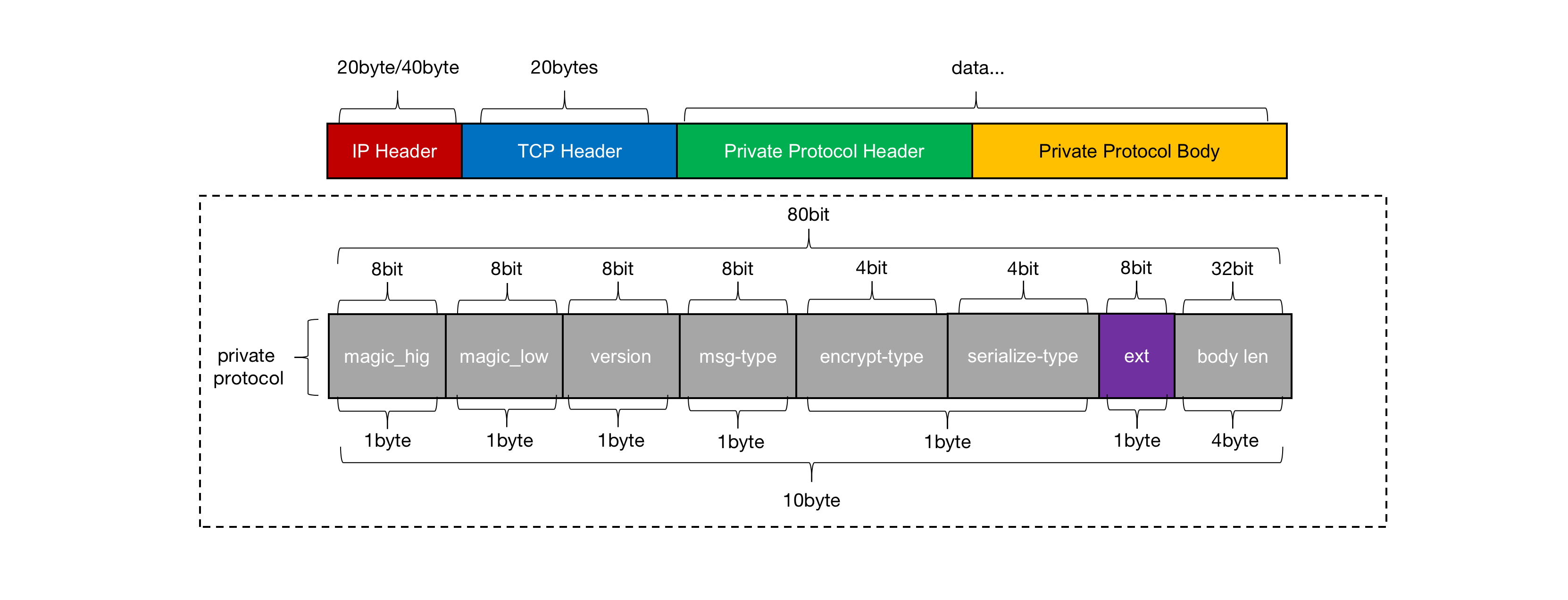
Think about it ,protocol What should be included in the ? Pictured 9 Shown , Fixed length protocol header+ variable protocol body Model as an example , remove body Necessary in request/response Out of data ,header It should at least include protocol Of magic、version、 Message type ( Used to judge request/response/heartbeat)、 Encryption type 、 Serialization type , as well as body Length and other fields . Of course ,
If you want to protocol It has certain expansibility , It is suggested to reserve one ext Field , And for the consideration of transmission efficiency ,header The design of partial compactness should be adopted
.
dubbo-protocol
dubbo3.x One of the biggest changes in the version is the introduction of a completely new design RPC agreement -traple, Strive to bring better for developers protocol Scalability at the same time , They are also moving towards with more firm determination cloud-native Stride forward . although traple At present, it is dubbo The official main push agreement , But in terms of current market recognition and familiarity ,dubbo2-protocol Still is the mainstream , Therefore, this article chooses the latter to explain .

Pictured 10 Shown ,
dubbo2-protocol It is a relatively compact structure , And based on fixed length header+ variable body Application layer of pattern protocol
.header The middle index bit is 1~2 Of byte To hold hig/low-magic; The index bit is 3 Of byte Used to store the message request id 、heartbeat、event, And serialization type ; The index bit is 5~12 Of byte Used to store reqid; The last index bit is 13~16 Of byte Is used to store the packet length . The specific code location is located in
ExchangeCodec#encodeRequest
in , As shown below :
protected void encodeRequest(Channel channel, ChannelBuffer buffer, Request req) throws IOException {
 //  Get serialization implementation
 Serialization serialization = getSerialization(channel, req);
 //  structure header
 byte[] header = new byte[HEADER_LENGTH];
 //  Fill the highest position with magic
 Bytes.short2bytes(MAGIC, header);
 //  The head of the 3 Bytes store the message request ID and serializer category
 header[2] = (byte) (FLAG_REQUEST | serialization.getContentTypeId());
 if (req.isTwoWay()) {
 header[2] |= FLAG_TWOWAY;
 }
 if (req.isEvent()) {
 header[2] |= FLAG_EVENT;
 }
 //  write in reqid
 Bytes.long2bytes(req.getId(), header, 4);
 // ======================= code body=======================
 int savedWriteIndex = buffer.writerIndex();
 buffer.writerIndex(savedWriteIndex + HEADER_LENGTH);
 ChannelBufferOutputStream bos = new ChannelBufferOutputStream(buffer);
 if (req.isHeartbeat()) {
 //  The heartbeat request data is always null
 bos.write(CodecSupport.getNullBytesOf(serialization));
 } else {
 ObjectOutput out = serialization.serialize(channel.getUrl(), bos);
 if (req.isEvent()) {
 encodeEventData(channel, out, req.getData());
 } else {
 //  Yes body Encoding
 encodeRequestData(channel, out, req.getData(), req.getVersion());
 }
 out.flushBuffer();
 if (out instanceof Cleanable) {
 ((Cleanable) out).cleanup();
 }
 }
 bos.flush();
 bos.close();
 //  obtain body length
 int len = bos.writtenBytes();
 checkPayload(channel, len);
 //  Write the packet length to header Of header[12-15] in
 Bytes.int2bytes(len, header, 12);
 buffer.writerIndex(savedWriteIndex);
 buffer.writeBytes(header);
 buffer.writerIndex(savedWriteIndex + HEADER_LENGTH + len);
}
Reason why dubbo2-protocol Is a compact protocol ,
It is because we have been adhering to “ The principle of sufficiency ”, Never waste any available resources
. In the above program example , Code
FLAG_REQUEST | serialization.getContentTypeId()
To express with 1byte To store the message request ID and serialization type respectively , The binary digits of the message request identifier are
0b10000000
, Serialization type hessian2 The number of binary digits of is
0b00000010
, Conduct
“|”
After operation , The final result is
0b10000010
. Here we need to pay attention to ,body After serialization, it will be written to... First ByteBuf in , Then the packet length is appended to header The middle index bit is 12~15 Of byte On , The last update ByteBuf Of writeIndex Write after 16byte Of header The data is done once protocol The encoding operation of .
dubbo How to deal with unpacking
dubbo The make up / The decoding process is based on Netty Of MessageToByteEncoder and ByteToMessageDecoder, Its internal real processing system / Decoding operation Handler For the inner class
InternalEncoder#encode
and
InternalDecoder#decode
.dubbo Handle TCP What is the idea of unpacking ? Simply speaking ,dubbo According to protocol The structure of is analyzed in turn header Data information in ,
If you find that ByteBuf Number of readable bytes in <header The packet length specified in , It means that the sending end must have a unpacking problem
, The decoder will immediately return an enumeration constant
NEED_MORE_INPUT
To the upstream , And reset readerindex, Then continue to wait for the callback
InternalDecoder#decode
Method before attempting to decode , To the end ByteBuf Number of readable bytes accumulated in >header The decoder will only decode when the packet length specified in , Pictured 11 Shown :

dubbo Really deal with body The type of deserialization operation is DecodeableRpcInvocation, Of course, by default, it is not directly controlled by netty Of worker Thread to support the execution of the deserialization task , It is
It is left to the downstream business thread to handle such time-consuming tasks
.
dubbo How to deal with sticking package problem
When everyone knows dubbo How to deal with TCP After unpacking , Next, let's take a look at TCP Stick package problem dubbo The solution . Pictured 11 Shown ,
In the same processing link , The decoder will use the spin method to parse a complete packet , until ByteBuf There is no more readable data in the
. Of course, if after parsing a packet ,ByteBuf When only some incomplete packets are left in the , The decoder will continue to process according to the unpacking process . The sticky packet processing logic is located in
DubboCountCodec#decode
in , As shown below :
public Object decode(Channel channel, ChannelBuffer buffer) throws IOException {
 int save = buffer.readerIndex();
 MultiMessage result = MultiMessage.create();
 do {
 Object obj = codec.decode(channel, buffer);
 if (Codec2.DecodeResult.NEED_MORE_INPUT == obj) {
 //  Fallback to previous read index position
 buffer.readerIndex(save);
 //  Exit loop , Wait for upstream feed data callback
 break;
 } else {
 //  Add the message to the set
 result.addMessage(obj);
 logMessageLength(obj, buffer.readerIndex() - save);
 save = buffer.readerIndex();
 }
 } while (true);
 if (result.isEmpty()) {
 return Codec2.DecodeResult.NEED_MORE_INPUT;
 }
 if (result.size() == 1) {
 return result.get(0);
 }
 return result;
}
The result set obtained when the decoder spin parses the sticky packet is stored in
MultiMessage#addMessage
in , Then it will be delivered to the upstream
InternalDecoder#decode
The way to join in List, Will eventually be passed on to pipeline Others on ChannelHandler To do it once RPC call .
Postscript
About Protocol That's all for our standard design , Interested students can read by themselves dubbo3.x Source code , Or refer to other relevant literature . If you have any questions in the reading process , Welcome to leave a message in the comments area to participate in the discussion .
Recommended articles :
Source series | Ali JVM-Sandbox Analysis of core source code
Ali senior experts analyze | HeartBeat Standard design of the scheme
In depth analysis of snowflake Algorithm
Practice | analyse Java16 New grammatical features
An interview with | My dialogue with master Bi Xuan
Calculate the force | Handwritten red black tree
Hard core series | In depth analysis of bytecode enhancement
Hard core series | In depth analysis of Java coroutines
White jade poison test | Gray architecture design scheme
Under the background of the new era Java Grammatical features
analyse Java15 New grammatical features
watchdog | Distributed lock architecture design -01
watchdog | Distributed lock architecture design -02
原网站版权声明
本文为[InfoQ]所创,转载请带上原文链接,感谢
https://yzsam.com/2022/164/202206130913154345.html


