当前位置:网站首页>Introduction to 51 Single Chip Microcomputer -- timer and external interrupt
Introduction to 51 Single Chip Microcomputer -- timer and external interrupt
2022-06-22 06:50:00 【In the morning, the rain shines】
Objective record
1. Timer
1.1. A preliminary understanding of timers
Before we know about timers, we first understand two basic concepts .
Clock cycle : Clock cycle T It's the smallest unit of time in time series , The specific calculation method is 1 / Clock source frequency , Generally, the crystal oscillator of single chip microcomputer is 11.0592 MHz Of , For this single-chip microcomputer system, the clock cycle is 1 / 11059200 second .
Machine cycle : The shortest time for our MCU to complete an operation . Machine cycles are mainly for assembly languages , In assembly language, the time used by each statement of the program is an integral multiple of the machine language , And the time taken by the statement can be calculated , and C The time taken by a language statement is uncertain , Affected by many factors .51 MCU series , Under its standard architecture, a machine language is 12 Clock cycles , That is to say 12 / 11059200 second . Now there are many enhanced 51 Single chip microcomputer , Its speed is relatively fast , yes , we have 1 individual The machine cycle is equal to 4 Clock cycles , yes , we have 1 A machine cycle is equal to 1 Clock cycles , In other words, its speed can generally meet the standard 51 Architecturally 3 times or 12 times .
After understanding the above concepts, we can start our play , Timers and counters . Timer and Counter It is the same module of single chip microcomputer , By configuring SFR( special function register ) Two different functions that can be implemented , We use timers in most cases , Therefore, this article mainly describes the timer function .
seeing the name of a thing one thinks of its function , Timers are used for timing . There is a register in the timer , After we let it start counting , The value of this register will be automatically added after each machine cycle 1, therefore , We can understand the machine cycle as the counting cycle of the timer . Just like our clocks , Every second , The number is automatically added 1, And this timer is the time of each machine cycle , That is to say 12/11059200 second , The number is automatically added 1. There is also a special place to pay attention to , The clock is added to 60 after , Seconds automatically become 0 了 , This kind of situation is called overflow in SCM or computer . How much will the timer overflow ? It will be mentioned later that the timer has a variety of working modes , Use different bit widths ( It refers to how many binary bits are used ), If so 16 Bit timer , That is to say 2 Bytes , The maximum value is 65535, Then add to 65535 after , add 1 Even if it overflows , If there are other digits , It's the same thing , about 51 Single chip microcomputer , After spilling , This value will directly become 0. Start with an initial value , Overflow after a certain time , This process is the meaning of timing .
1.2. Timer register
The standard 51 There are... Inside the single chip microcomputer T0 and T1 These two timers ,T Namely Timer Abbreviation , A lot now 51 Series MCU will also add additional timer , Let's start with the timer 0 and 1. I mentioned before , For each function module of the single chip microcomputer , All by its SFR, That is, special function registers are used to control . Special function registers related to timers , There are the following , You don't need to remember the names and functions of these registers , You just need to know about it , Use it every time , You can always check the manual , Find the name of each register and the function of each register .
The registers in the figure below are used to store the count value of the timer .TH0/TL0 be used for T0,TH1/TL1 be used for T1.

The following figure shows the timer control register TCON Bit allocation of ( Address 0x88、 Addressable addressing )

The following figure shows the bit description of timer control register
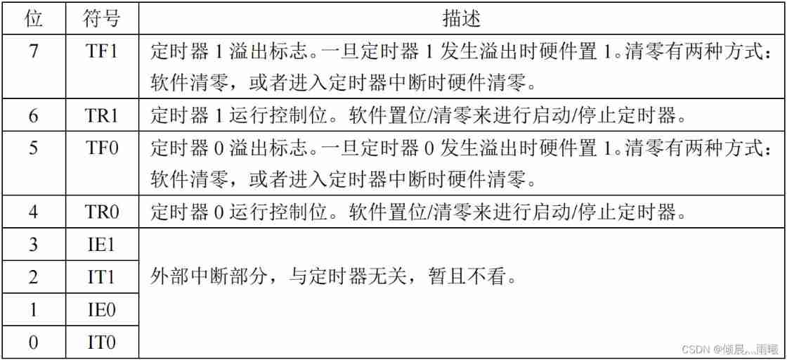
In the description above , Just write the hardware settings 1 Or clear 0 Of , It means that once the conditions are met , SCM will automatically complete the action , Just write software to set 1 Or clear 0 Of , It means that we must use the program to complete this action , If you encounter this kind of description in the future, you won't explain it separately .
about TCON This SFR, Among them is TF1、TR1、TF0、TR0 this 4 We need to understand , They correspond to T1 and T0, We use a timer 1 As an example to explain , So timer 0 Empathy . First look at TR1, When we write in the program TR1 = 1 in the future , The timer value will be automatically increased every machine cycle 1, When we write in the program TR1 = 0 in the future , The timer will stop adding 1, Its value will remain unchanged .TF1, This is a flag bit , His function is to tell us that the timer overflows . For example, our timer is set to 16 Bit pattern , So every machine cycle ,TL1 Add 1 once , When TL1 Add to 255 after , add 1,TL1 become 0,TH1 Will add 1 once , So it goes on to TH1 and TL1 All are 255( namely TH1 and TL1 Composed of 16 Bit integer numbers are 65535) in the future , add 1 once , It will overflow ,TH1 and TL1 At the same time, they all become 0, Just a spill ,TF1 It automatically becomes 1, Tell us the timer overflowed , Just give us a signal , Let us know that the timer overflowed , It has no effect on whether the timer continues to run .
The timer has several operating modes , The choice of working mode is determined by TMOD To control .
The following figure shows the bit allocation of timer mode register ( Address 0x89、 Non bitable addressing )

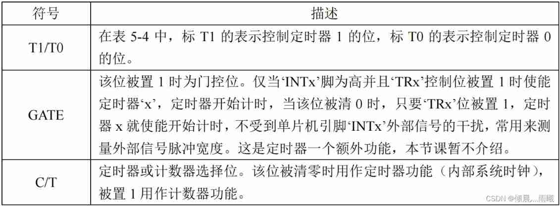
The following figure shows the bit description of the timer mode register
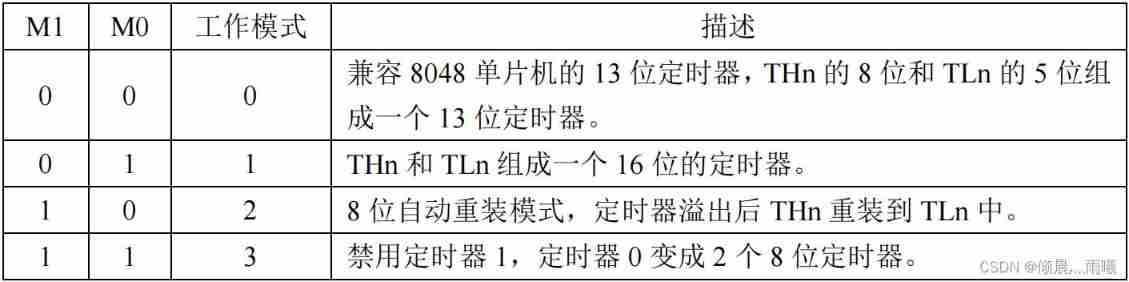
The following figure shows the timer mode register M1 / M0 Working mode
In the timer control register TCON The bit allocation of is finally marked with “ Addressable addressing ”, The bit allocation of the timer mode register is marked as “ Non bitable addressing ”. That is to say : such as TCON There is a person named TR1, We can do it directly in the program TR1 = 1 This kind of operation . But yes TMOD The bit in the, for example ( T1 ) M1 = 1 Such an operation is wrong . If we want to operate, we must operate the entire byte at once , That is to say, it must be done at one time TMOD All bit operations , It is not possible to operate on one of them alone , So can we change only one bit without affecting the values of the other bits ? Certainly. , You will learn the method in the following articles , Don't care about it now .
The above figure lists the timer 4 Working mode , And the pattern 0 To be compatible with the old 8048 Series single chip microcomputer , current 51 This mode is rarely used , And the pattern 3 According to my application experience , Its function is in mode 2 It can completely replace , So it's basically unnecessary , So let's focus on learning patterns 1 And pattern 2.
Pattern 1, yes THn and TLn Formed a 16 Bit timer , The counting range is 0~65535, After spilling , As long as it's not right THn and TLn Reassign , From 0 Start counting . Pattern 2, yes 8 Bit auto reload mode , Only TLn Do plus 1 Count , Counting range 0~255,THn The value of does not change , But keep the original value ,TLn After spilling ,TFn Just put it directly 1 了 , also THn The original value is assigned directly to TLn, then TLn Count from the newly assigned number . This function can be used to generate the communication baud rate of the serial port , When we talk about serial port, we need , In the first half of this article, we focus on learning patterns 1. In order to deepen our understanding of the principle of timers , Let's take a look at his model 1 Circuit diagram of .
OSC The box indicates the clock frequency , because 1 One machine cycle is equal to 12 Clock cycles , So that d Is equal to 12. Underside GATE The gate on the right is a non gate circuit , On the right is an or door , To the right is an and gate circuit .
It can be seen from the picture , The lower part of the circuit controls the upper part , Let's take a look at how the following controls , We use a timer 0 For example .
1、TR0 And the result of the lower side or gate circuit shall be and calculated ,TR0 If it is 0 Words , And it must be 0, So if you want the timer to work , that TR0 Must be set 1.
2、 The and gate result here is 1, Then the result of the front or the door must also be 1 Talent . stay GATE Position as 1 Under the circumstances , After a non gate, it becomes 0, Or gate circuit results to be 1 Words , that INT0 namely P3.2 The pin must be 1 Under the circumstances , This time the timer will work , and INT0 The pin is 0 Under the circumstances , Timer does not work , This is it. GATE The role of bit .
3、 When GATE Position as 0 When , After a non gate, it will become 1, So no matter INT0 What level is the pin , After passing through or gate circuit, it must be 1, The timer will work .
4、 To make the timer work , It is automatically added 1, From the picture, there are two ways , The first way is to turn the switch to the arrow on the top , Namely C/T = 0 When , One machine cycle TL Will add 1 once , When the switch is turned to the arrow below , namely C/T =1 When ,T0 Pin is P3.4 A pulse comes from the pin ,TL Just add 1 once , This is the counter function .
1.3. The application of timer
Understand the timer related registers , So let's do a timer program , Consolidate what we have learned . Our program in this lesson uses a timer first 0, When using the timer , The following steps are required :
First step : Set special function register TMOD, Configure the working mode .
The second step : Set the count register TH0 and TL0 Initial value of .
The third step : Set up TCON, adopt TR0 Set up 1 To get the timer to start counting .
Step four : Judge TCON The register of TF0 position , Monitor timer overflow .
Before writing the program , We must first learn how to calculate the time with a timer . Our crystal oscillator is 11.0592M, The clock period is 1/11059200, The machine cycle is 12/11059200, If you want to schedule 20ms, Namely 0.02 second , To pass x A machine cycle gets 0.02 second , Let's figure it out x*12/11059200=0.02, obtain x= 18432.16 The bit timer overflow value is 65536( because 65535 add 1 Is overflow ), So we can do this , First give TH0 and TL0 An initial value , Let them pass 18432 After a machine cycle, it just reaches 65536, That is, overflow , Overflow can be detected TF0 Worth knowing , It just happens to be 0.02 second . So the initial value y = 65536 - 18432 = 47104, Turn into 16 Hexadecimal is 0xB800, That is to say TH0 = 0xB8,TL0 = 0x00.
#include <reg52.h>

sbit LED = P1^4;

void main()
{

 	unsigned char cnt = 0; // Define a count variable , Record  T0  Overflow times
 	LED = 0;
 	TMOD = 0x01; // Set up  T0  For mode  1
 	TH0 = 0xB8; // by  T0  Assign initial value to  0xB800
 	TL0 = 0x00;
 	TR0 = 1; // start-up  T0

 	while (1)
 	{

 		if (TF0 == 1) // Judge  T0  Overflow or not
 		{

 			TF0 = 0; //T0  After spilling , Clear interrupt flag
 			TH0 = 0xB8; // And assign the initial value again
 			TL0 = 0x00;
 			cnt++; // Count value self adding  1
 			if (cnt >= 50) // Judge  T0  Whether the overflow reaches  50  Time
 			{

 				cnt = 0; // achieve  50  The count value will be cleared after the next time
 				LED = ~LED; //LED  Take the opposite :0-->1、1-->0
 			}
 		}
 	}
 }

2. External interrupt
2.1. Interrupt background
Let's imagine a scene like this : I'm cooking a pot of water with gas in the kitchen at the moment , And boiling a pot of water just needs 10 minute , I am a subject , Boiling water is a goal , And I can only boil water here all the time , Because once the water boils , If it overflows to extinguish the gas , It may cause a disaster . But at this time , I heard it on TV again 《 Pleasant goat and grey wolf 》 The theme song of , The show will begin soon , I really want to break out of the door , Go to see my favorite cartoon . However , I heard the sound of the kettle “ Gu Gu ” The sound of , I know : Unless the water boils , Otherwise I won't be able to enjoy my favorite cartoons .
There is only one me here , And I have two things to do , One is watching TV , One is boiling water , Television and boiling water are two independent objects , They are done at the same time . Among them, boiling water requires 10 minute , But you don't need to know the process of boiling water , Just get the result that the water boils , It only takes a few seconds to lift the kettle and turn off the gas . So the way we take is : When boiling water , Set an alarm clock , timing 10 minute , Then I can watch TV at ease . When 10 Minutes is up , The alarm goes off , Now the water is boiling , I'll go and put out the gas , Then go back and watch TV .
What is the relationship between this scene and the single chip computer ?
There are many similar scenes in the process of program processing of single chip microcomputer , When the single-chip microcomputer is concentrating on doing one thing ( Watching TV ) When , There will always be one or more urgent or non urgent things happening , We need to pay attention to , There are some things we need to stop working on and deal with immediately ( For example, the water is boiling ), Only when it is finished , To go back and finish the work just now ( Watching TV ). In this case, the interrupt system of single chip microcomputer should play its powerful role , Use interruptions wisely , Not only can we gain the ability to deal with emergencies , And it can make the single chip microcomputer “ meanwhile ” Complete multiple tasks .
2.2. Application of timer interrupt
In the last section we learned about timers , In fact, the general usage of timers is to interrupt , I deliberately used the query method in the previous section , Is the use of if(TF0==1) Such statements start with a timer , Because timers and interrupts are not the same thing , Timer is a resource of SCM module , A module that really exists , And interrupt , Is a single-chip operating mechanism . Especially beginners , Many people mistakenly think that timers and interrupts are the same thing , Only the timer will trigger the interrupt , But in fact, many events trigger interrupts , except “ Boil water ”, also “ Someone rang the doorbell ”,“ There's a call ” wait .
standard 51 There are two registers for controlling interrupts in the single chip microcomputer , One is the interrupt enable register , The other is the interrupt priority register , Here we first introduce the interrupt enable register , The following table . With some enhanced 51 The advent of single-chip computers , There may be additional registers , Everyone understands what we are talking about here , Others can be understood and used by studying the data manual .
The table below for :IE—— Bit allocation of interrupt enable register ( Address 0xA8、 Addressable addressing )

The table below for :IE—— Bit description of interrupt enable register

Interrupt enable register IE Bit 0~5 Controlled 6 Interrupt enable , And the first 6 I didn't use , The first 7 Bit is the main switch . The main switch is equivalent to the main power gate in our home or student dormitory , and 0~5 This bit 6 A bit is equivalent to each sub switch . So in other words , We just need interrupts , Just write EA = 1 This sentence , Turn on the interrupt master switch , And then use which minute to interrupt , Then open the corresponding control bit .
Now we will use interrupt to realize the dynamic display of digital tube .
The following figure for : Digital tube dynamic display stopwatch program flow chart

//*************** Use 74HC138 Auxiliary control nixie tube ************//
#include <reg52.h>

sbit ADDR0 = P1^0;
sbit ADDR1 = P1^1;
sbit ADDR2 = P1^2;
sbit ADDR3 = P1^3;
sbit ENLED = P1^4;

unsigned char code LedChar[] = {
     // Digital tube display character conversion table
 0xC0, 0xF9, 0xA4, 0xB0, 0x99, 0x92, 0x82, 0xF8,
 0x80, 0x90, 0x88, 0x83, 0xC6, 0xA1, 0x86, 0x8E
};

unsigned char LedBuff[6] = {
     // Nixie tube display buffer , initial value  0xFF  Make sure that it doesn't light up when you start
 0xFF, 0xFF, 0xFF, 0xFF, 0xFF, 0xFF
};

unsigned char i = 0; // Dynamic scan index
unsigned int cnt = 0; // Record  T0  Interruption times
unsigned char flag1s = 0; //1  Second timing flag

void main()
{

	unsigned long sec = 0; // Record the number of seconds elapsed
 	EA = 1; // Enabling always interrupts
 	ENLED = 0; // Can make  U3, Select control nixie tube
	ADDR3 = 1; // Because it needs to change dynamically  ADDR0-2  Value , So there is no need to initialize
	TMOD = 0x01; // Set up  T0  For mode  1
	TH0 = 0xFC; // by  T0  Assign initial value to  0xFC67, timing  1ms
 	TL0 = 0x67;
 	ET0 = 1; // Can make  T0  interrupt
 	TR0 = 1; // start-up  T0
 	while (1)
 	{

 		if (flag1s == 1) // Judge  1  Second timing flag
 		{

 			flag1s = 0; //1  The second timing flag is cleared
 			sec++; // The second count is self incremented  1
 // The following code will  sec  According to the decimal bit, extract from low to high and turn it into nixie tube display characters
 			LedBuff[0] = LedChar[sec%10];
 			LedBuff[1] = LedChar[sec/10%10];
 			LedBuff[2] = LedChar[sec/100%10];
 			LedBuff[3] = LedChar[sec/1000%10];
 			LedBuff[4] = LedChar[sec/10000%10];
 			LedBuff[5] = LedChar[sec/100000%10];
 		}
 	}
 }
/*  Timer  0  Interrupt service function  */
void InterruptTimer0() interrupt 1
{

	TH0 = 0xFC; // Reload initial values
 	TL0 = 0x67;
 	cnt++; // The count value of the number of interrupts plus  1
 	if (cnt >= 1000) // interrupt  1000  Next instant  1  second
 	{

 		cnt = 0; // Clear the count value to restart the next  1  Second timing
 		flag1s = 1; // Set up  1  The second timing flag is  1
 	}
 // The following code completes the dynamic scan and refresh of the nixie tube
 	P0 = 0xFF; // Show hidden
	 switch (i)
 	{

  		case 0: ADDR2=0; ADDR1=0; ADDR0=0; i++; P0=LedBuff[0]; break;
 		case 1: ADDR2=0; ADDR1=0; ADDR0=1; i++; P0=LedBuff[1]; break;
 		case 2: ADDR2=0; ADDR1=1; ADDR0=0; i++; P0=LedBuff[2]; break;
 		case 3: ADDR2=0; ADDR1=1; ADDR0=1; i++; P0=LedBuff[3]; break;
 		case 4: ADDR2=1; ADDR1=0; ADDR0=0; i++; P0=LedBuff[4]; break;
 		case 5: ADDR2=1; ADDR1=0; ADDR0=1; i=0; P0=LedBuff[5]; break;
 		default: break;
 	}
 }
In this program , There are two functions , One is the main function , One is the interrupt service function . The main function main() We don't have to say , Highlight the interrupt service function , Its writing format is fixed , First interrupt the front of the function void Indicates that the function returns null , That is, the interrupt function does not return any value , The function name is InterruptTimer0(), This function name can be arbitrarily chosen on the premise that it conforms to the function naming rules , We chose this name to make it easy to distinguish and remember , Then is interrupt This keyword , There must be no mistake , This is a keyword specific to interrupts , In addition, there is a number behind it 1, This number 1 How did you come here ? Let's look at the table below
The table below for : Interrupt query sequence

Now let's look at the second line T0 interrupt , To enable this interrupt, its interrupt enable bit ET0 Set up 1, When its interrupt flag bit TF0 Turn into 1 when , It will trigger T0 It's broken , Then it is time to execute the interrupt function , How can the SCM find this interrupt function ? It depends on the interrupt vector address , therefore interrupt The number following the interrupt function number x It is based on the interrupt vector , Its calculation method is x*8+3= Vector address . Of course, the table has been put in the first column , We can just find it out and use it . Only this and nothing more , The naming rules of interrupt functions are clear . After the interrupt function is written , Whenever an interrupt condition is met and an interrupt is triggered , The system will automatically call the interrupt function . For example, the above program , Always in the main program while(1) In the loop of , If the program has 100 That's ok , When executed 50 Line time , The timer overflowed , Then the MCU will immediately run to the interrupt function to execute the interrupt program , After the interrupt program is completed, it will automatically return to the previous step 50 Continue to execute the following procedure at line , This ensures that the dynamic display interval is fixed 1ms, It will not cause the jitter of the nixie tube display due to inconsistent program execution time .
2.3. Interrupt priority
Content of interrupt priority , Let me give you a brief introduction , We will understand it in detail later in the practical application .
When talking about the background of interrupt generation , We just talked about watching TV and boiling water , But there are more complicated things in real life , For example, I'm watching TV , It's time to call , I'm going to enter the phone “ interrupt ” In the program , While answering the phone , I heard the sound of water boiling , Boiled “ interrupt ” It happened, too , We have to put down the phone , Turn off the gas first , Then come back and listen to the phone , Finally, after listening to the phone, watch TV , Here comes a priority problem .
There's another situation , When we're watching TV , At this time, I heard the sound of water boiling , Boiled “ interrupt ” It happened. , We're going into the gas off “ interrupt ” In the process , While turning off the gas , The telephone rang , And this time , Our treatment is to turn off the gas first , Then answer the phone , Finally watch TV .
From these two processes , We can come to a conclusion , Is the most urgent thing , Once it happens , We don't care where we were “ Program ” among , We must deal with the most urgent things first , Deal with other things after it is finished . In our MCU program, sometimes it is the same , There is a general emergency interruption , There is a particularly urgent interruption , It depends on the specific system design , This involves the concepts of interrupt priority and interrupt nesting , In this section, we will briefly introduce the related registers , No routine instructions .
There are two interrupt priorities , One is preemptive priority , One is inherent priority , Let's first introduce preemption priority .
The table below for :IP—— Bit allocation of interrupt priority register ( Address 0xB8、 Addressable addressing )

The table below for :IP—— Bit description of interrupt priority register

IP Every bit of this register , Indicates the preemptive priority of the corresponding interrupt , The reset value of each bit is 0, When we set a bit to 1 When , The priority of this bit is higher than that of other bits . For example, we set up PT0 Position as 1 after , When the MCU executes in the main loop or any other interrupt program , Once the timer T0 Interrupt occurred , As a higher priority , The program will run to T0 In the interrupt program . In turn, , When the MCU is T0 When executing in an interrupt program , If other interrupts occur , Or will it continue T0 Interrupt the program , Until the T0 After the execution of the interrupt program in , Will execute other interrupt programs .
When entering a low priority interrupt to execute , If another high priority interrupt occurs , Then enter the high priority interrupt execution immediately , After handling high priority interrupts , Then return to handle low priority interrupts , This process is called interrupt nesting , Also known as preemption . So the concept of preemptive priority is , High priority interrupts can interrupt the execution of low priority interrupts , So as to form nesting . Of course the other way around , Low priority interrupts cannot interrupt high priority interrupts . So since there is preemptive priority , Naturally, there are non preemptive priorities , Also known as inherent priority . In the table Interrupt query sequence The last column in gives the inherent priority , Please note that , In the number of interrupt priority , Generally, the smaller the number, the higher the priority . You can see from the table that there are 1~6 common 6 The priority of the level , One difference between priority and preemption priority is , It doesn't have preemptive features , That is, even if a high priority interrupt occurs during the execution of a low priority interrupt , Then the high priority interrupt can only be responded after the low priority interrupt is executed . Since you can't seize , So what's the use of this priority ?
The answer is arbitration when multiple interrupts exist at the same time . For example, multiple interrupts occur at the same time , Of course, the probability of this happening is very low , But another situation is much more common , That's why we temporarily shut down the total interruption for some reason , namely EA=0, After executing a piece of code, the total interrupt is enabled again , namely EA=1, Then during this period of time, it is likely that multiple interrupts have occurred , But because the total interrupt is off , So they didn't get a response , And when the total interrupt is enabled again , They will respond to the request at the same time , Obviously , At this time, there must be a sequence , This is the role of non preemptive priority —— As shown in the table Interrupt query sequence in , Who has the highest priority responds first , Number and line up , Get the response in turn .
Collaboration between preemptive priority and non preemptive priority , It can make the single chip microcomputer interrupt the orderly work of the system , There will be no endless nesting , It can also ensure that urgent tasks are given priority when necessary .
边栏推荐
- MySQL ifnull processing n/a
- Reprint the Alibaba open source project egg JS technical documents cause "copyright disputes". How to use the loose MIT license?
- 六月集训(第22天) —— 有序集合
- Difference between thread and process
- Single cell paper record (part6) -- space: spatial gene enhancement using scrna seq
- Four functional interfaces (required)
- iframe框架,,原生js路由
- 深度解析Optimism被盗2000万个OP事件(含代码)
- IO intensive and CPU intensive
- Dijin introduces digi connectcore voice control software for connectcore system module
猜你喜欢

【5G NR】RRC连接重建解析
![[5g NR] ng interface](/img/28/98e545104e4530d0e8f65e9ac993ca.png)
[5g NR] ng interface

Databricks from open source to commercialization
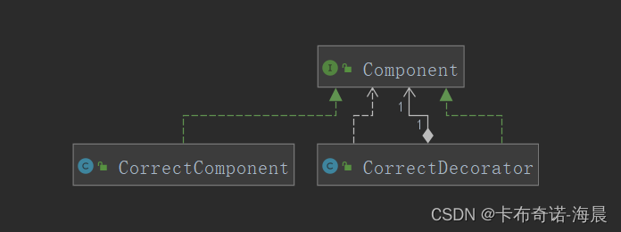
代理模式与装饰模式到底哪家强
【OpenAirInterface5g】高层模块接口及itti实体线程创建

Reprint the Alibaba open source project egg JS technical documents cause "copyright disputes". How to use the loose MIT license?
![[5g NR] UE registration management status](/img/e6/2415ea09b5faa4c5f204d8d67dbb6a.png)
[5g NR] UE registration management status

Dynamically create object execution methods

Introduction to 51 Single Chip Microcomputer -- the use of Keil uvision4

Producer and consumer issues
随机推荐
仙人掌之歌——上线运营(5)
Record of problems caused by WPS document directory update
The song of cactus - marching into to C live broadcast (2)
Pytest data parameterization & data driven
iframe框架,,原生js路由
Xh_ CMS penetration test documentation
【5G NR】NAS连接管理—CM状态
[PHP] composer 安装
代理模式与装饰模式到底哪家强
[M32] single chip microcomputer SVN setting ignore file
Event preview edgex developer summit @ Nanjing station is coming!
Detailed explanation of eight locks
[rust daily] January 23, 2022 webapi benchmarking
[rust notes] 01 basic types
Chrome 安装 driver
Lock lock (key)
【M32】单片机 svn 设置忽略文件
EMC solutions
【OpenAirInterface5g】ITTI消息收发机制
[5g NR] ng interface