当前位置:网站首页>Do a Cisco experiment!
Do a Cisco experiment!
2022-07-23 12:50:00 【hgswnsa】
Cisco experiment
If you don't say much, go to the link first
link :https://pan.baidu.com/s/1Sf57hgWrs6ZdTBJ3k9XxUw
Extraction code :6666
The installation process is very simple , Just go on to the next step
After installation, it's like this 
Experiment 1 :
Four sets pc machine , Two switches ,pc Machine and pc Computers can communicate with each other
1、 Draw the topology , Connect the cable 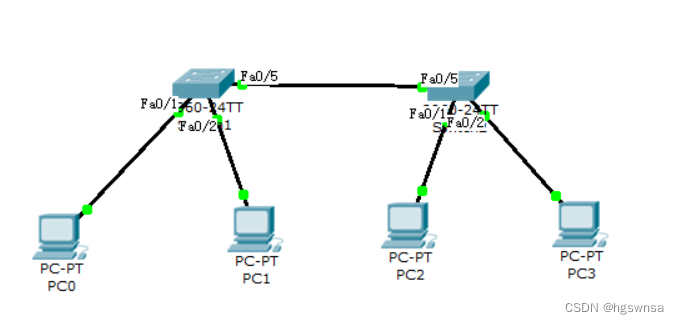
2、 to pc Machine configuration is good ip Address , Here the 192.168.1.0/24 (192.168.1 Network segment )
Here's a demonstration PC0 How to configure ip, other pc Machine photo gourd painting ladle
Left mouse button PC machine -> Click on Desktop -> Click on IP Configuration
choice Static, Input IP Address and subnet mask ( In the first column IP Address input is legal , Clicking the second column will automatically fill in the subnet mask )
Other three pc Machine configuration ip Is the same procedure , It's just their ip Different addresses 
Four stations pc All machines are configured ip, We can do it next ping Tested
3、ping test
can ping Just say pc Computers can communicate with each other
Yes? ping?
Left mouse button PC machine -> Click on Desktop -> Click on Command Prompt
Use ping Pick up ip Address Go to ping
The following is ping Effect of communication 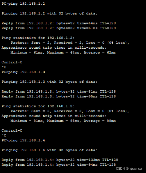
Experiment two :
Switch 1 And switches 2 Create three each VLAN,VLAN10、VLAN20、VLAN30
Switch port assignment :
VLAN10:F0/1~F0/3;
VLAN20:F0/4~F0/6
VLAN30:F0/7~F0/9
requirement : Same across switches vlan Can communicate with each other
Here we use 6 platform pc Computer and two switches simulate
Interface access F0/3、F0/6、F0/9
1、 Draw the topology , Connect the cable 
2、 Plan well ip and vlan
3、 To configure ip
The steps are omitted here
4、 add to vlan ( Add three switches to both switches VLAN)
Left mouse button switch -> Click on Config -> Click on VLAN Database -> Input number and name -> Click on Add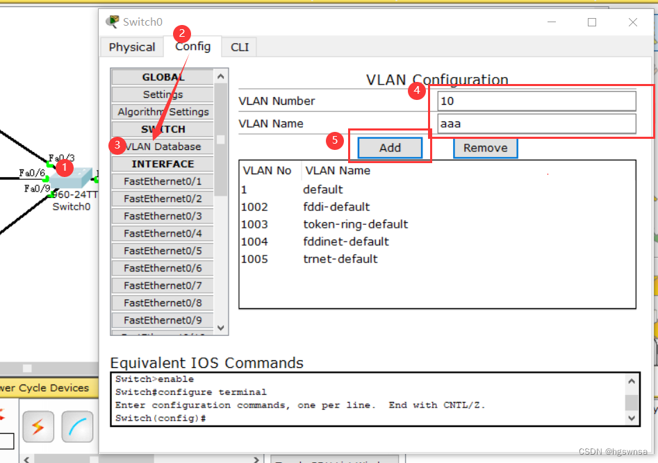
Three VLAN Add to complete 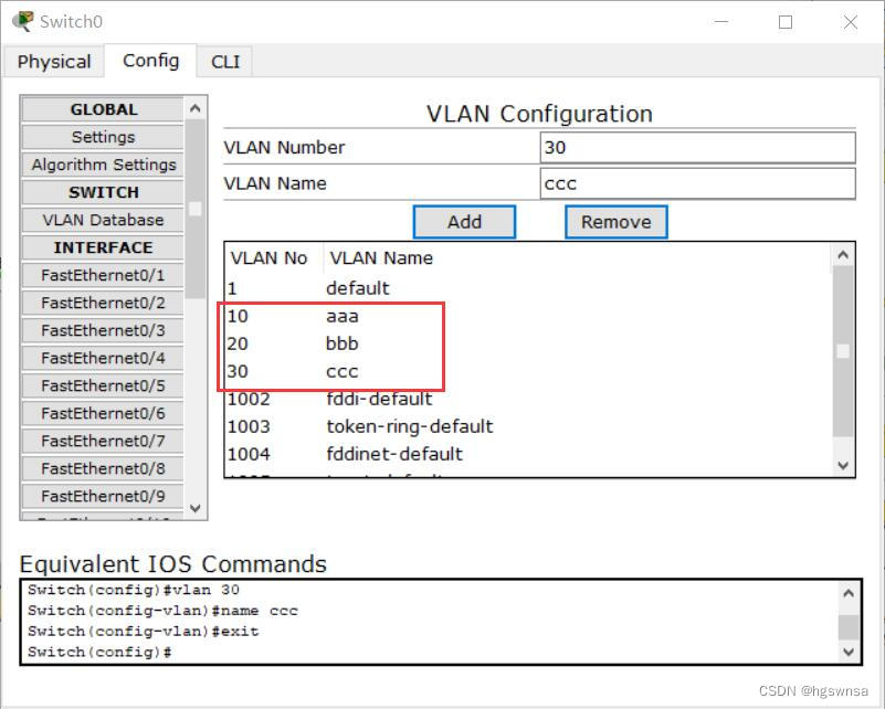
5、 Add the interface to the corresponding VLAN
Only the left side is shown here , The same operation on the right


6、 To configure trunk link ( Each interface should be configured as trunk Pattern )

7、 test 
This achieves the same across switches vlan Communication between
边栏推荐
- Analyze redis cluster
- HCIP---HCIA知识回顾(一)
- Unity3d:ugui source code eventsystem input system FAQ
- C # custom bidirectional linked list
- 第一类错误离我们有多远
- 剑*offer—— 链表逆序
- 详解TCP连接的建立
- Implementation of heap and heap sorting
- Analysis ideas of strong consistency and weak consistency and concurrency skills of distributed scenarios
- Explain the interactive data flow and block data flow of TCP in detail
猜你喜欢

[Reading Notes "Phoenix architecture" - a large-scale distributed system with reliable architecture. Zhou Zhiming] (I)

Common sort -- merge sort (recursive and non recursive) + count sort

HCIP---BGP ---边界网关协议

学习日记——(路由与交换技术)网络地址转换 NAT技术

Hcip--- BGP related configuration (Federal chapter)

MySQL performance optimization, index optimization

flask项目celery使用redis sentinel中遇到的坑

unity3d:Assetbundle模拟加载,同步加载,异步加载,依赖包加载,自动标签,AB浏览器,增量打包

C语言也能写植物大战僵尸

C# 自定义Queue队列集合
随机推荐
Analysis of inheritablethreadlocal and Alibaba's transmittablethreadlocal design ideas
C#:快速排序,有相同的数字会忽略,然后继续先前的寻找方向去找下一个满足要求的数字进行替换
C#:TopK:1万个数取前最大的100,堆排序
GameFramework:打包资源,打随app发布包,打包生成文件夹说明,上传资源至服务器,下载资源,GameFreamworkList.dat 与GameFrameworkVersion.dat
[database] basic theory
Design experience of log file IO system
详解TCP的交互数据流和成块数据流
Unity3d:UGUI源碼,Rebuild優化
GameFramework:资源热更代码分析,检查版本信息,下载版本文件,校验版本文件,得到更新文件数量,下载文件,TaskPool
Unity3d:UGUI,UI与特效粒子层级,2018.2以上版本BakeMesh,粒子在两个Image之间且在ScrollView
C # custom stack
C# 自定义双向链表
牛客面试必考真题【算法篇】高频Top200 题目汇总
剑*offer—— 链表逆序
In depth analysis of replication in redis
OSPF的路由策略和流量抓取
学习日记——(路由与交换技术)DHCP(动态主机配置协议)
Hcip --- BGP --- border gateway protocol
PDF在线预览,pdf.js的使用
《wireshark网络分析就是这么简单》知识点与技巧