当前位置:网站首页>[open source tutorial] DIY tutorial of step-by-step electric adjustment [Author: I love Laurie, Laurie]
[open source tutorial] DIY tutorial of step-by-step electric adjustment [Author: I love Laurie, Laurie]
2022-06-21 05:30:00 【Gutie_ bartholomew】
Preface :
common The motor There are three kinds of : Brush motors 、 No brush motor 、 Stepper motor . There is a brush 、 Brushless Electrical regulation There are many , It seems that the electric adjustment of the stepping motor is really not . The step-by-step electrical adjustment is made by the landlord , It can be regarded as the first !
But on the contrary , Why doesn't anyone do step-by-step electrical regulation , It may also be that the stepper motor is difficult to do anything on the aircraft model , Small torque , The speed is slow , Do not drive the propeller .
Therefore, the direct drive stepping motor is definitely not needed . This post is mainly aimed at those micro stepping motors with reduction gears or screw rods , What is it used for , It depends on your brain holes .

Introduction to stepping electric regulator :
It is similar to the ordinary brush two-way electric regulator , Input the throttle signal of the receiver , Speed of stepping motor 、 Forward and reverse adjustment .
Support common two-phase four wire 、 Four phase five wire stepping motor .( Short the two pins to select the motor type , The default mode of no short circuit is two-phase four wire )
Use 2A Motor drive module , Common stepper motors are less than 1A, Sufficient current .
According to the test , Large volumes are common (25/35) The maximum frequency of the stepping motor does not exceed 1KHz, Considering the reduction ratio of gears , The speed should not be too slow , Therefore, the speed regulation range of the electric commutation time is 11ms ~ 1ms.( The micro screw motor can reach up to 0.4ms, Please change the program by yourself )
Voltage range : Those made according to the tutorial only support 2S voltage ! If you want to support 1S voltage , It is necessary to stabilize the voltage for the single-chip microcomputer independently ; If you want to support 3S, Need replacement support 3S Voltage motor drive module .
Stepping The steering gear brief introduction :
All things are short and good , The stepper motor can only move forward step by step , Instead, it is widely used in printers 、 Engraving machine and other high-end instruments . Naturally, it can also be used in steering gear .
And the stepping motor can calculate the characteristics of walking distance by counting steps , The step-by-step actuator is very simple and can be realized without potentiometer !
The only problem that hinders the stepper actuator is centering : Because there is no position feedback , I don't know my position when the steering gear is powered on .
Lucky to get the imagination of friends Max Your move : Just make a detent at the maximum stroke of the steering gear , When the power is on, the steering gear first turns to the detent and does not move , I know indirectly that my position is the farthest ! Then the program will automatically return to the center . A genius idea .
(PS: In terms of performance, the step-by-step steering gear can not be compared with 6 Huisheng steering gear for one yuan , Only useful for special applications , Please measure yourself )
Pay attention to the use of step steering gear :
Load resistance shall not be greater than the maximum torque , Do not jam the rudder , Otherwise you will lose your step .
The maximum travel detent must be made, or it will not be able to return to the center correctly .
The reduction ratio of asynchronous motor may be different , If your motor is different from the owner , The stroke is too large or too small , Follow the tutorial to modify the program .
One 、 Material preparation
1,STC15W104 Single chip microcomputer ( No longer recommended 15F104W, Although compatible . Many people have the problem of switching out electricity , After questioning, I found that they were all used 15F104W. The chipbook is right , But many people don't do well in power supply , It will make the single chip computer restart frequently . Therefore, only wide voltage ones are recommended in the future 15W)

2, Dual motor drive module

1, The simplest electric regulator in history was made , There are only two components !( It is more convenient to brush the firmware for the single chip microcomputer in advance )

2、 On module IN1、IN2 And IN3、IN4 They are the control ports of two motor drives , It is welded with the single chip microcomputer

3、 SCM also needs power supply , Fly two wires as shown in the figure : Black is the ground , Red is 5V( Here, the module is cleverly used 5V Zener diode , The voltage stabilizing chip of the single chip microcomputer is omitted )

4、OK, That's all. So easy The production of is finished .
After welding the wire, it can be used .

3、 ... and 、 Firmware and updates
Usage flow :
The power on meeting played three times , Wait for the throttle signal ……
Detect the middle position of the throttle and play three more times , Push the oil valve to turn .
Calibrate the travel :( After downloading the firmware, it comes with a standard trip , Use directly without calibration )
If the travel is wrong , The throttle is at the highest power on position , Wait for the music to play twice , The program automatically records the maximum throttle signal ; Throttle return , Wait for the music to play twice , Program to record the throttle center position . Complete calibration . ( Manual squint : Do you feel so familiar ,, And brush PN The use method of electric regulator is exactly the same )
to update : Stepper actuator fixings
The circuit does not change , A deceleration stepping motor can be turned into a steering gear by using the steering gear fastener .
Modify the stroke of the stepping actuator by yourself :
Because different stepping motors have different reduction ratios , Maybe you use different motors with different stroke , You can modify the code and compile the new firmware .( Will not compile reference 《 SCM class 》 Lesson 12 )
To facilitate modification , It is defined in the program :
// Parameter configuration
#define MAX 1000 // Maximum travel steps Corresponding rotation angle
#define Phase_Time 1200 // Commutation time 1.2ms The longer the time, the slower the speed
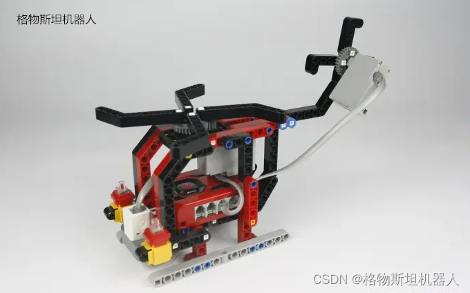
Some people don't know how to connect the five wire stepping motor , Take this motor for example , Generally, red is the common positive pole ,ABCD Just count down in order

边栏推荐
- 七大设计原则
- Mac NAMP Pro comes with MySQL 5.7 setup SQL_ Model remove only_ FULL_ GROUP_ Invalid by may be caused by:,
- 基於SSM+MySQL+LayUI+JSP的公共交通運輸信息管理系統
- Glycosylated albumin research - abbexa ELISA kit to help!
- Randomly create circular, triangular or rectangular objects, store them in the array, and calculate the area and perimeter of each shape
- Launcher page cut Animation
- librosa | 梅尔谱图最通俗的解释
- File contains vulnerability - allow_ url_ Fopen and allow_ url_ Include details
- House sales and leasing system based on ssh+mysql
- MyBaits-plus
猜你喜欢

VMware新建OracleLinux6.5虚拟机
![[development of API interface based on oauth2] 3. User defined authorization method](/img/a6/d8f9c882059f3cae008b80263a4cec.png)
[development of API interface based on oauth2] 3. User defined authorization method

还不了解最新版Kubernetes?一节公开课解决你所有疑问

Flower sales system based on jsp+servlet+mysql
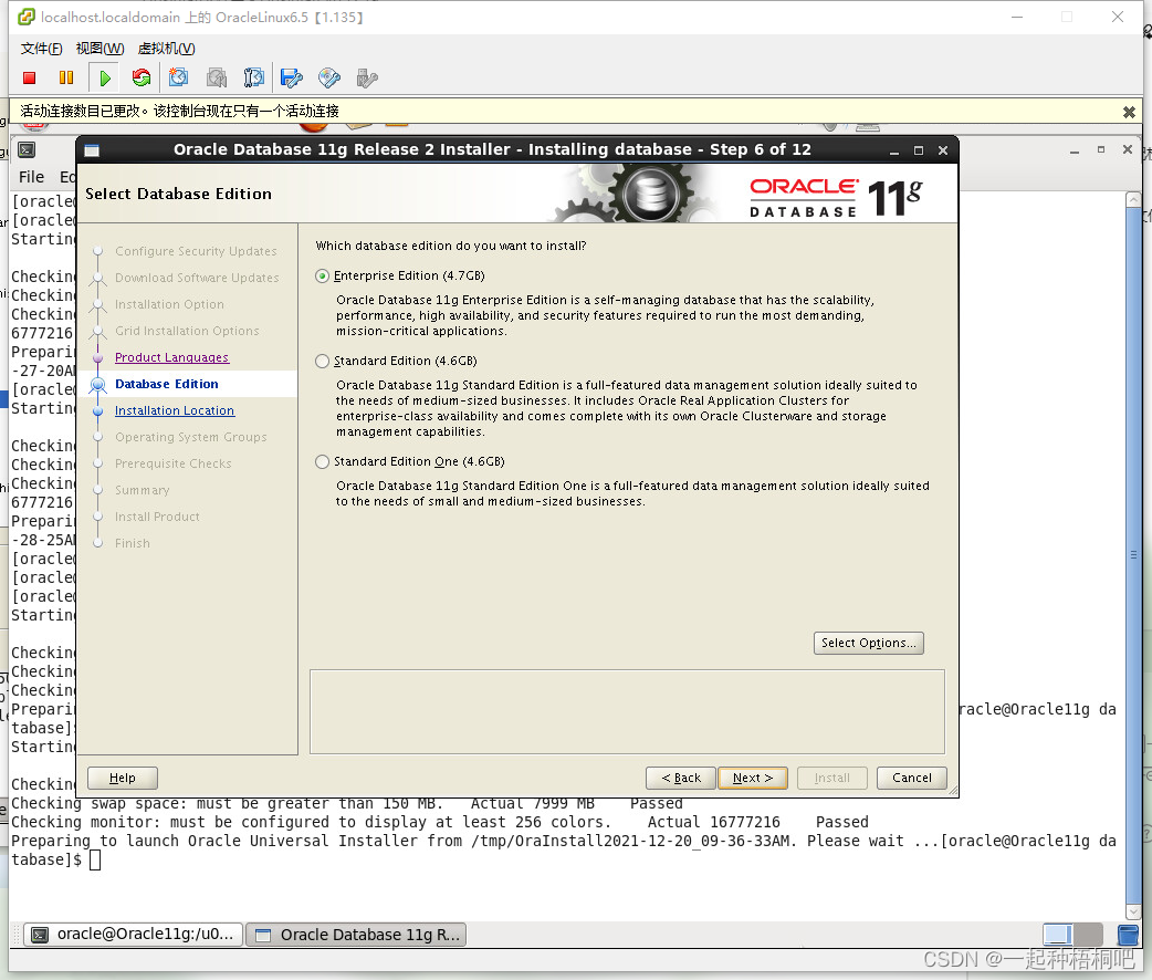
Oraclelinux6.5 graphical installation Oracle11g
Physical principle of space design in maker Education

Comprehensive arrangement of character recognition methods
AI OPEN DAY---如何通过采用开源技术来优化产品和业务收益

Qualcomm snapdragon processor DSP
批改网如何解除老师设置的禁止复制粘贴
随机推荐
Common storage types
Steam education subject integrates the intelligent scene of AR
VMware新建OracleLinux6.5虚拟机
Unscrambling the education mode of compound new engineering robot
launcher切页动画
In depth analysis of short URL Technology
Système de gestion de l'information sur les transports publics basé sur SSM + MySQL + layui + jsp
Abnova 11 dehydrogenation TXB2 ELISA Kit instructions
83. (cesium chapter) how to run the cesium example
vscode+platformIO开发STM32(七)
Individual template of the 13th National tournament of the Blue Bridge Cup ------ another year
Qualcomm LCD bring up process
Oracle笔记 之 update语法
登录认证(一) —— 几种登录方式简介
Mac MAMP Pro installation PHP extension method
Global and Chinese market of blood filter 2022-2028: Research Report on technology, participants, trends, market size and share
Comprehensive arrangement of character recognition methods
关于PHP签名中的容易犯错问题记录
Assembler: maximizing
At the codeless Explorer conference, Qingliu invites you to discuss the way of digital transformation practice