当前位置:网站首页>RF analyzer demo setup
RF analyzer demo setup
2022-06-23 11:28:00 【Hua Weiyun】
RF Analyzer Demo build
First time editor 2022 year 6 month 22 Japan 08:52:36 Used as a process record file
Documents to read
- Basic concept and hardware architecture pg269-rf-data-converter_2.6 Add Baidu network disk link in the future
- The main reference tutorial RFAnalyzer-Tutorial
- SCGUI Use UG xtp517-zcu111-system-controller-c-2019-1
Software to download
- Development and utilization IDE Vivado 2020.1 Version above
- The software needed to configure the development board rdf0475-zcu111-system-controller-c-2019-1.zip
- RF_ANAlyzer Upper computer rf_analyzer_1.5
The hardware that needs to be prepared
Zynq UltraScale+ RFSoC ZCU111
XM500 Signal transfer card 
SMA Short wiring
USB A-micro Cable
12V 7.5A DC power supply
The development board will be equipped with , With a computer atx Power supply or sfx The power supply should also ok. Confirm the line sequence before power on
Feasible sequence of operation
1 Configure the clock on the board
For the configuration of the on-board clock, please refer to my other blogZCU111 Development board clock configuration
- decompression rdf0475-zcu111-system-controller-c-2019-1 Open after BoardUI.exe

- If you connect a board , You can select the serial number from the drop-down menu and click ok
- stay clocks Sets There are six positions in the interface that need to be configured
1、2 Is the direct write frequency value
3、4、5、6、7 You need to enter the absolute path of the configuration file . After the input file is configured successfully , The configured clock frequency will be displayed on the corresponding line .
If the configured clock frequency is not displayed, the configuration fails .
Under the software installation folder rdf0475-zcu111-system-controller-c-2019-1\zcu111_scui\BoardUI\tests\ZCU111\clockFiles There are three official configuration files in
The clock on the board can be configured to the frequency value shown in the following table . Configuration tutorial reference XTP518
| The clock | frequency /MHz |
|:–:|:–:|
| 1 | 300 |
| 2 | 156.25 |
| 3 | 156.25 |
| 4 | 122.88 |
| 5 | 122.88 |
| 6 | 122.88 |
| 7 | 122.88 |
There are two things to note here 2022 year 6 month 23 Japan 09:41:13


- The configuration method used is to use XLINX Official System Control GUI, For the required address, see ZCU111 Development board clock configuration , The clock configuration method is to use GUI Interface , Then enter the absolute path of the configuration file , But in fact, the software has a limit on the length of the input file path string . It is not clear what the limit is , But using the same configuration file , Absolute path long configuration will fail ( Try 3 Time ), Move the files to the root directory of the hard disk , Reconfiguration can be successful .
- The value of the clock configuration needs to be recorded , Because the clock generated at this time is used as a subsequent generation demo Of tile Of ref clk, So in Ip When generating, pay attention to modifying the corresponding parameters , otherwise RF DC The PLL will fail to start because the PLL cannot operate normally .
2 Create a new one demo Bitstream
Reference resources RFAnalyzer-Tutorial Of page18-21 Page operation , Here I encountered the following problems
- vivado Version issue for , To do this, you need VVD2018.3 Version above , What I use here is 2020.1, First use 18.1 No corresponding IP
- initialization IP Configuration problem of , The description given in the original text is Configure the IP as per your board requirement
But as a cute new , I don't know what I want to configure . Here first according to my own understanding , Configure any one , It is also possible to use the preset configuration .- A question , After selecting the chip model , Directly through IP CATALOG Generated , No constraint file specified . Limited by my current level , System generated XDC File contents Don't understand, . Later, we will find out how the actual hardware constraints are completed .
2022 year 6 month 22 Japan 11:41:21 The first generated bitstream can be downloaded , But eventually it started RFanalyzer when , Can't start ADDA, Prompt for PLL unlocked, The clock on the board is not configured properly . You need to study the clock tree on the board .
2022 year 6 month 22 Japan 18:09:07 The on-board clock has been reconfigured and the on-board clock has been reset IP Corresponding settings during initialization REFclk Value , To be able to start AD_DA, And make use of analyzer To operate
3 Download the bitstream to the development board
The development board I use is Zynq UltraScale+ RFSoC ZCU111 Assessment Kit
You can read about this development board first ug1271-zcu111-eval-bd This document , Learn how to use the development board , And the hardware resources on the board .
The development board needs to use DC12v Power supply , The original cable is 12V 7.5A 90W
Use USB Line link boards and computers , The board has been integrated JTAG Debug interface .
in addition to ,RFDC Of gui Use Gigabit Ethernet for communication configuration . So I also prepared a network cable , I don't know how to use it .
After connecting the board, you can download the bit stream for debugging .
of demo The bit stream generated in the sample , This bit stream already contains microblaze Soft core and RFDC_RDanalyze etc. PL Some required wiring information , It also encapsulates microBlaze The executable of . stay vivado Directly download the generated bitstream in , Or in analyzer You can download it from .
Please be sure to link analyzer Configure the clock file before , Otherwise, the communication may fail .
Plan for the next step
- be familiar with analyzer Various operations of . And then in demo Insert another... In the project of the sample microblaze Soft core development , Switch through simple logic to make use of the original analyzer And the newly implanted soft core API Cross validation of interfaces .
- Add some knowledge about RF communication system , Take a look at the whole RF Functions and functions of various components in the system .
- Learn how to configure the clock tree on the board
边栏推荐
- 每日一题day7-1652. 拆炸弹
- 使用tensorflow2创建神经网络
- 电容参数哪里找!?
- 最简单DIY基于STM32的远程控制电脑系统①(电容触摸+按键控制)
- 如何用 Redis 实现一个分布式锁
- Rancher 2.6 全新 Monitoring 快速入门
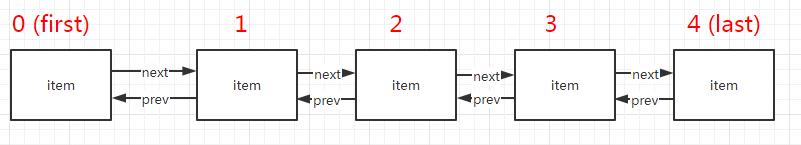
- Deep analysis and Simulation of list
- ESP32-CAM无线监控智能网关的设计与实现
- "Core" has spirit "lizard", ten thousand people are online! Dragon Dragon community walks into Intel meetup wonderful review
- L'outil de périphérique deveco aide au développement de périphériques openharmony
猜你喜欢
Analysis of LinkedList source code

运行时应用自我保护(RASP):应用安全的自我修养

一年多时间时移世易,中国芯片不断突破,美国芯片却难以卖出

OpenHarmony应用开发【01】

开发增效利器—2022年VsCode插件分享
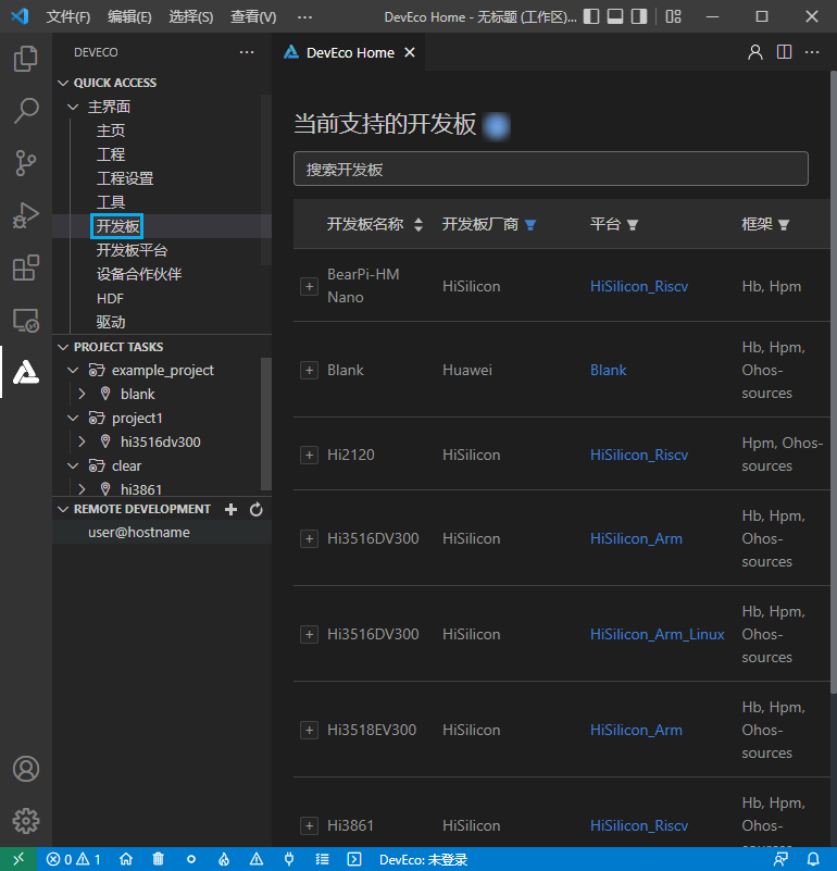
DevEco Device Tool 助力OpenHarmony設備開發

塔米狗 | 投资人类型分析以及企业投资类型分析

Vone新闻 | 旺链科技赋能众享链网自组织管理,打造企业级联盟DAO
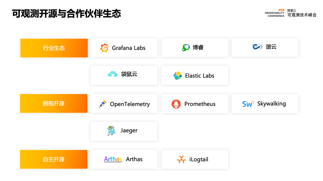
More than observation | Alibaba cloud observable suite officially released

How Huawei cloud implements a global low latency network architecture for real-time audio and video
随机推荐
Gradienttape of tensorflow2
力扣 1319. 连通网络的操作次数
Attack and defense drill collection | 3 stages, 4 key points, interpretation of the blue team defense whole process outline
【云舟说直播间】-数字安全专场明天下午正式上线
互联网奇迹-小米究竟是怎么盈利
深潜Kotlin协程(十四):共享状态的问题
RF Analyzer Demo搭建
长安LUMIN是否有能力成为微电市场的破局产品
1154. day of the year
MAUI使用Masa blazor组件库
Torch weight to mindspore
最简单DIY基于STM32的远程控制电脑系统①(电容触摸+按键控制)
电感有极性吗?
華為雲如何實現實時音視頻全球低時延網絡架構
UWA new | real person real machine test new overseas model zone
Interview Manual of social recruitment Tencent high P (Senior Product Manager)
The simplest DIY pca9685 steering gear control program based on the integration of upper and lower computers of C # and 51 single chip microcomputer
如何用 Redis 实现一个分布式锁
攻防演练合集 | 3个阶段,4大要点,蓝队防守全流程纲要解读
DevEco Device Tool 助力OpenHarmony设备开发