当前位置:网站首页>Bug STM32 advanced timer (haha, to tell you the truth, the hardware timer can't reflect its strength. In fact, I want to send the kernel timer. Just think about it. Take your time)
Bug STM32 advanced timer (haha, to tell you the truth, the hardware timer can't reflect its strength. In fact, I want to send the kernel timer. Just think about it. Take your time)
2022-06-23 04:17:00 【Hua Weiyun】
Advanced timer
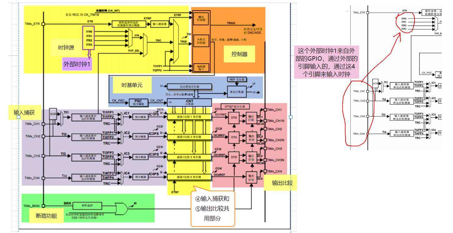
Clock source
First, let's talk about the percentage of clock sources 99 Use the internal , other 3 Basically, I don't need it , The following three are for understanding , There is something wrong , A little confused
- Internal clock source CK_INT
- External clock mode 1— External GPIO Tix(x=1 2 3 4)
- External clock mode 2— External GPIO ETR
- Internal trigger input
Internal clock source
- The internal clock source comes from RCC Of TIMx_CLK
- TIMx_CLK So what is that equal to ? How to determine the ?
External clock mode 1
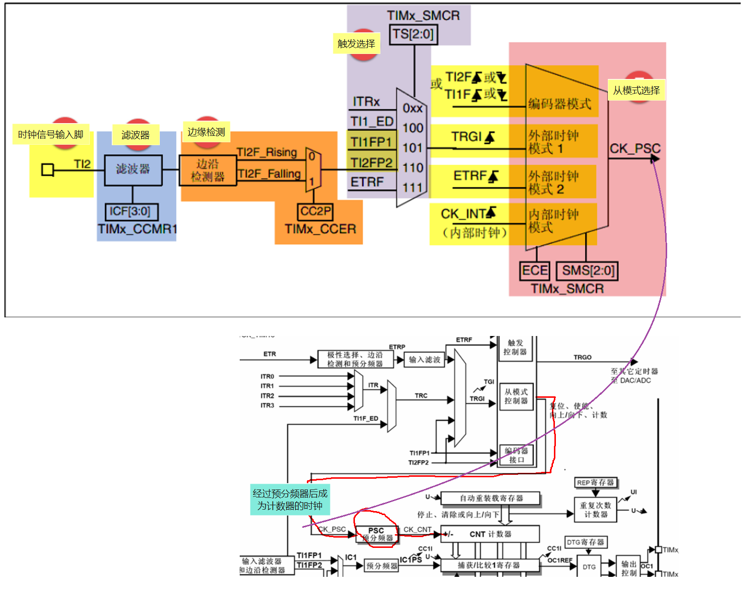
Clock signal input pin
- External GPIO TIx, Corresponding :TIMx_CH1/2/3/4
- TIM_CCMRx Bit CCxS[1:0] To configure , among CCMR1 control TI1/2, CCMR2 control TI3/4
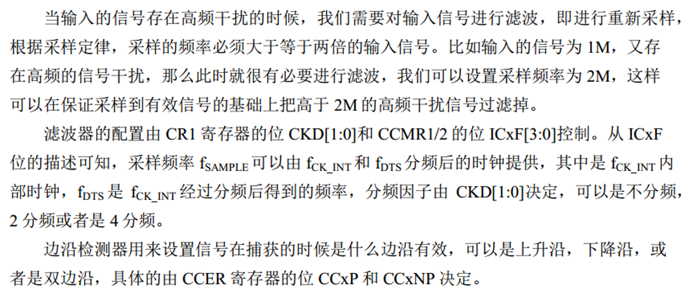
filter
- If the frequency of external clock signal is too high or mixed with high frequency interference signal , We need to use filters to ETRP Signal resampling , To achieve the purpose of reducing frequency or removing high frequency interference
- from TIMx_CCMRx Bit ICxF[3:0] To configure
Edge detection
- The edge detection signal comes from the output of the filter , Before it becomes a trigger signal , Edge detection is needed , Decide whether the rising edge is valid or the falling edge is valid .
- from TIMx_CCER Bit CCxP and CCxNP To configure
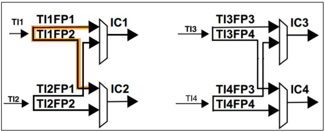
Trigger selection
- When using external clock mode 1 when , There are two trigger sources , One is the filtered timer input 1( TI1FP1) And filtered timer input 2( TI2FP2)
- from TIMx_SMCR Bit TS[2:0] To configure
Enable counter
- Through the top 5 After one step , Finally, we just need to enable the counter to start counting , External clock mode 1 The configuration is complete .
- The enable counter consists of TIMx_CR1 Bit CEN To configure .
External clock mode 2
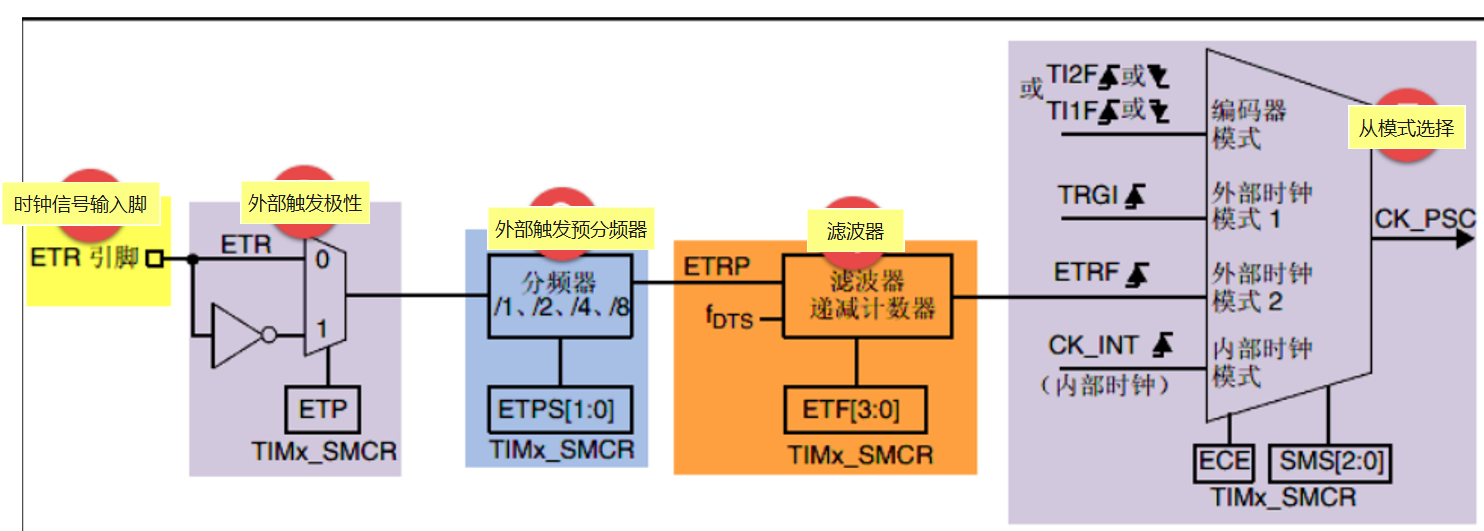
Clock signal input pin
When using external clock mode 2 When , The clock signal comes from a specific input channel of the timer TIMx_ETR, Only 1 individual .
External trigger polarity
- come from ETR The signal of pin input can be selected as rising edge or falling edge
- The specific reason is TIMx_SMCR Bit ETP To configure
External trigger prescaler
- because ETRP The frequency of the signal must not exceed TIMx_CLK( 180M) Of 1/4, When the frequency of the trigger signal is very high , You have to use a frequency divider to reduce the frequency
- The specific reason is TIMx_SMCR Bit ETPS[1:0] To configure
filter
- If ETRP The frequency of the signal is too high or mixed with high-frequency interference signals , A filter pair is required ETRP Signal resampling , To achieve the purpose of reducing frequency or removing high frequency interference
- The specific reason is TIMx_SMCR Bit ETF[3:0] To configure , Among them fDTS It's from the internal clock CK_INT Divide the frequency to get , The specific reason is TIMx_CR1 Bit CKD[1:0] To configure
From mode selection
- The filtered signal is connected to ETRF After pin , The trigger signal becomes the external clock mode 2 The input of , In the end, it's equal to CK_PSC, And then drive the counter CNT Count .
- Specific configuration TIMx_SMCR Bit ECE by 1 You can select the external clock mode 2
Enable counter
- Through the top 5 After one step , Finally, we just need to enable the counter to start counting , External clock mode 2 The configuration is complete
- The enable counter consists of TIMx_CR1 Bit CEN To configure .
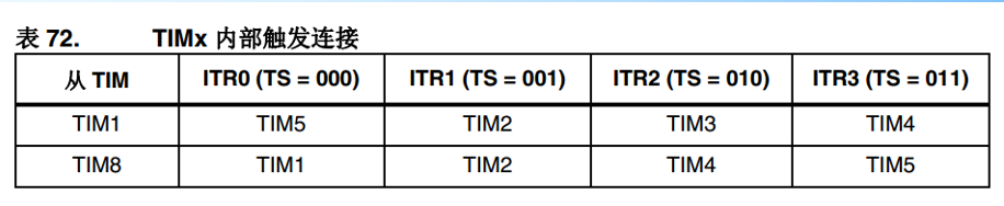
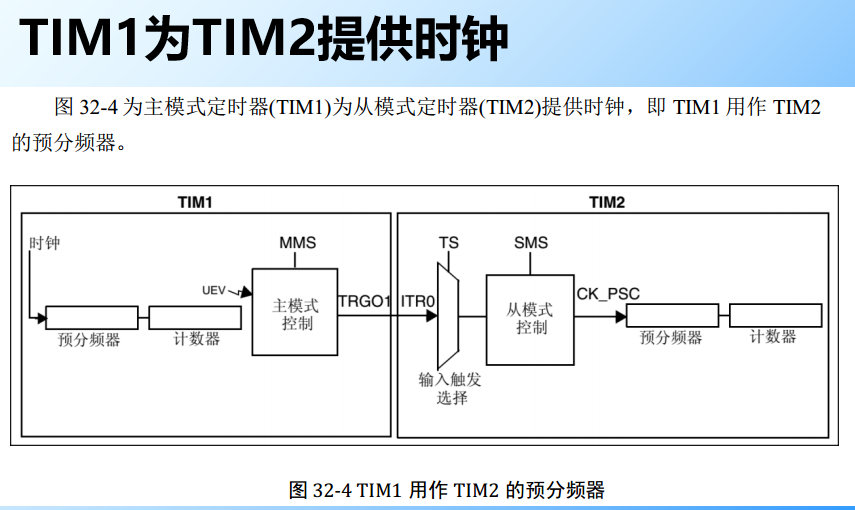
Internal trigger input
- The internal trigger input is a prescaler that uses one timer as another . In terms of hardware, advanced control timer and general timer are internally connected , Timer synchronization or cascade can be realized .
- from TIMx_SMCR Bit TS[2:0] To configure
controller
- The controller is used to control , Sending commands
- CR1、CR2、SMCR、CCER, Mainly learn these registers .
Time base unit
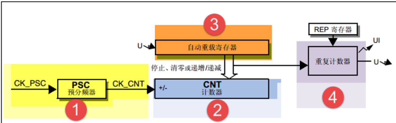
Composition of time base unit
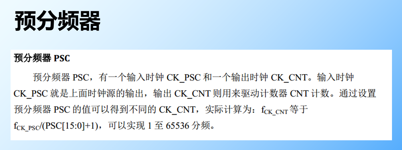
- 16 Bit prescaler PSC,PSC
- 16 Bit counter CNT, CNT
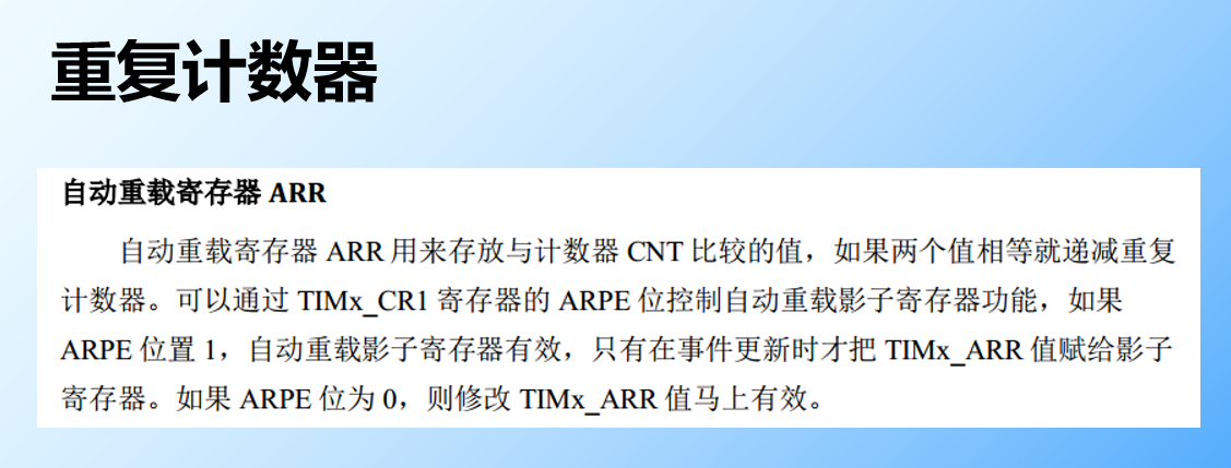
- 8 Bit repetition counter RCR,RCR( Advanced timer is unique )
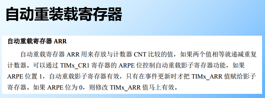
- 16 Bit automatic reload register ARR,ARR
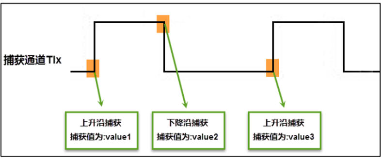
Input capture
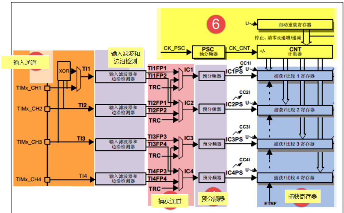
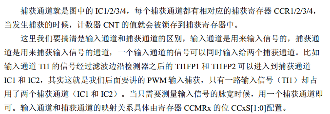
Input channel
When using the signal to be measured from the external pin of the timer TIMx_CH1/2/3/4 Get into , Usually called TI1/2/3/4, In the later explanation of acquisition, we all use the following words for the signal to be measured TIx It's the standard name .
Input filtering and edge detection
Capture channels
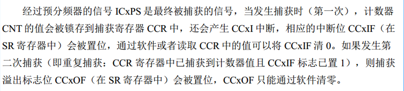
Preassigned frequency counter
- ICx The output of the signal goes through a prescaler , Used to capture once when deciding how many events occur .
- Specifically, the register CCMRx Bit ICxPSC To configure , If you want to capture every edge of the signal , No frequency division .
Capture register
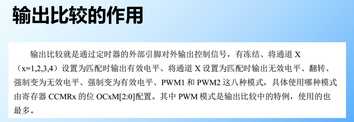
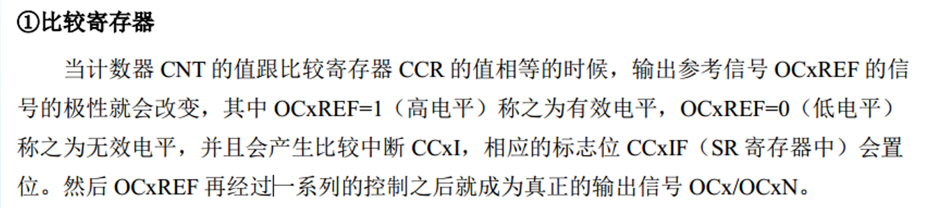
Output comparison

Output comparison register
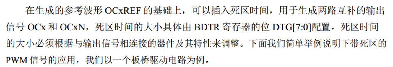
Dead zone generator
Half bridge drive circuit with dead band insertion

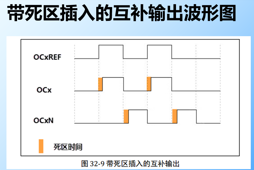
Complementary output waveform with dead band insertion
Output control
Output pin

Input capture application
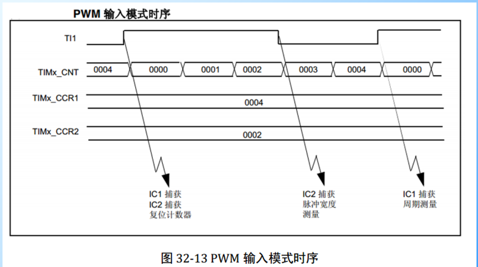
Measure pulse width and frequency
PWM The input mode
- The output comparison mode has a total of 8 Kind of , What is commonly used is PWM Pattern .
- By register CCMRx Bit OCxM[2:0] To configure .

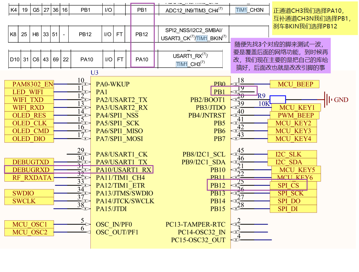
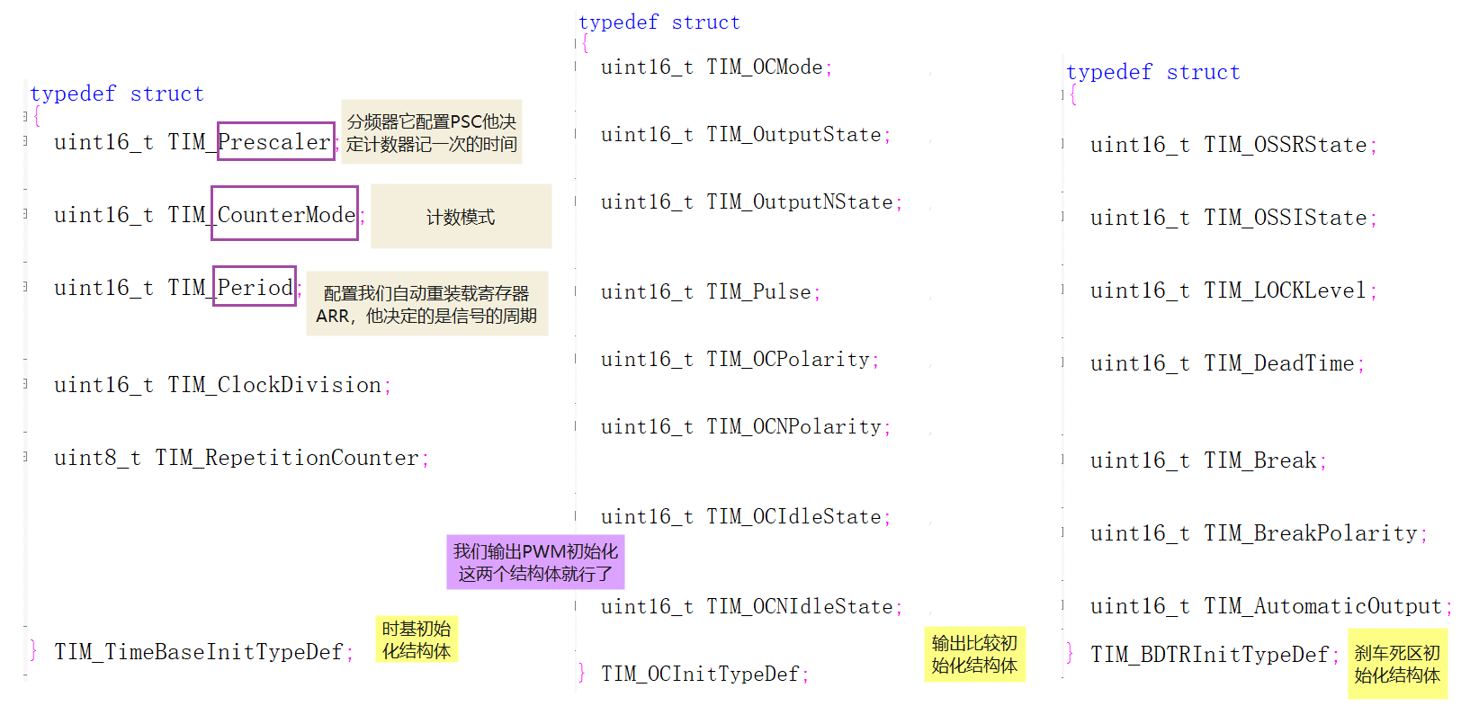
Code
First we choose our feet , Here we use advanced timer
PWM Complementary output experiment , Dead time , With brake control
Complementary needs two feet , Deadband can be configured by software , The brake also needs a foot . We can only use advanced timers 1 了 , No, 8
边栏推荐
- TRTC setaudioroute invalid problem
- Differences between MyISAM and InnoDB of MySQL storage engine
- 【LeetCode】23. Merge K ascending linked lists
- Software project management 8.4 Software project quality plan
- [greed] leetcode991 Broken Calculator
- 选择排序法
- Is LinkedList a one-way linked list or a two-way linked list?
- 【LeetCode】两数之和II
- 城链科技董事长肖金伟:践行数据经济系国家战略,引领数字时代新消费发展!
- Not just offline caching- On how to make good use of serviceworker
猜你喜欢

高效的远程办公经验 | 社区征文

Flutter怎么实现不同缩放动画效果

如何处理大体积 XLSX/CSV/TXT 文件?
![[machine learning] wuenda's machine learning assignment ex2 logistic regression matlab implementation](/img/eb/0d4caf0babbe14f51f4dbf1b9ae65d.png)
[machine learning] wuenda's machine learning assignment ex2 logistic regression matlab implementation

冒泡排序法

x64dbg 基本使用技巧
![[OWT] OWT client native P2P E2E test vs2017 construction 4: Construction and link of third-party databases p2pmfc exe](/img/cd/7f896a0f05523a07b5dd04a8737879.png)
[OWT] OWT client native P2P E2E test vs2017 construction 4: Construction and link of third-party databases p2pmfc exe
【机器学习】 吴恩达机器学习作业 ex2逻辑回归 Matlab实现

支持在 Kubernetes 运行,添加多种连接器,SeaTunnel 2.1.2 版本正式发布!

怎么使用Shell脚本实现监测文件变化
随机推荐
Insérer le tri directement
Pytorch---Pytorch进行自定义Dataset
如何保证应用程序的安全性
仿360桌面悬浮球插件
What is the potential of dmail based on Web3.0? First round financing of $10 million?
8 key indicators to measure technology debt in 2022
For patch rollback, please check the cbpersistent log
redisTemplate和cacheManager操作redis有什么不同
d重载嵌套函数
靜態查找錶和靜態查找錶
TRTC setaudioroute invalid problem
Weekly Postgres world news 2022w02
聊聊内存模型和内存序
【LeetCode】179. Maximum number
粒子动画背景登录页面particles.js
城链科技董事长肖金伟:践行数据经济系国家战略,引领数字时代新消费发展!
[tcapulusdb knowledge base] [list table] example code for deleting the data at the specified location in the list
【LeetCode】23. Merge K ascending linked lists
mysql,字段问题
自媒体时代的贤内助——AI 视频云