当前位置:网站首页>Aurora8b10b IP usage-01-introduction and port description
Aurora8b10b IP usage-01-introduction and port description
2022-06-21 06:17:00 【Vuko-wxh】
Aurora 64B/66B IP summary
Introduce
Aurora 8B/10B The kernel support AMBA agreement 、AXI4-Stream The user interface . This kernel uses Zynq、Artix-7、Kintex-7 and Virtex-7 series 、UltraScale and UltraScale+ The high-speed serial transceiver on series Aurora 8B/10B agreement .
characteristic
- The throughput range is 480 Mb/s to 84.48 Gb/s Universal data channel .
- Support up to 16 A continuous bond 7 series GTX/GTH、UltraScale GTH or UltraScale+ GTH Transceivers and up to four bonding GTP Transceiver .
- Aurora 8B/ accord with 10B Protocol specification v2.3.
- Low cost of resources .
- Easy to use based on AXI4-Stream Frame of ( Or flow ) And flow control interface .
- Automatically initialize and maintain channels .
- Full duplex or simplex operation .
- 16 Bit scrambler / descrambler .
- For user data 16 Bit or 32 Bit cycle redundancy check (CRC).
- Hot plug logic .
- Configurable DRP/INIT The clock .
- GTREFCLK And the kernel INIT_CLK The list of / Differential clock option .
IP summary
Vivado The tool can be a with configurable data path width Aurora 8B/10B The kernel generates source code . The kernel can be simplex or full duplex , It has one of two simple user interfaces and optional flow control .Aurora 8B/10B The channel structure is shown in the figure below , It is an extensible for high-speed serial communication 、 Lightweight link layer protocol . The agreement is open , have access to Xilinx FPGA Technology to implement . This protocol is usually used for simple 、 Low cost 、 Application of high rate data channel , And used to transmit data between devices using one or more transceivers .

Aurora 8B/10B The kernel is connecting to Aurora The channel will be initialized automatically , And transmit data freely in the channel in the form of frame or data stream .
Aurora Frames can be any size , And can be interrupted at any time . The gap between valid data bytes is automatically filled with idle to keep locking and prevent excessive electromagnetic interference . Flow control can be used to reduce the rate of incoming data or to send short high priority messages over the channel .
Flow is single 、 Endless frames . In the absence of data , The transmission is idle to keep the link active . Aurora 8B/10B The kernel using 8B/10B Coding rules detect single bit and most multi bit errors . Too many bit errors 、 Disconnection or device failure can cause the kernel to reset and attempt to reinitialize the new channel .
application
Aurora 8B/10B Low cost of kernel resources 、 Scalable throughput and flexible data interface , Therefore, it can be used in various applications . Examples of core applications include :
- Chip to chip link : Replacing parallel connections between chips with high-speed serial connections can significantly reduce PCB The required routing and number of layers on the . The kernel uses the lowest FPGA Resource costs are provided for use GTP、GTX and GTH The logic required for transceivers .
- Board to board and backplane links : The kernel uses standard 8B/10B code , Make it compatible with many existing cable and backplane hardware standards . Aurora 8B/10B The kernel can be extended in terms of line rate and channel width , To allow the use of cheap traditional hardware in new high-performance systems .
- Simplex connection ( A one-way ):Aurora The protocol provides an alternative to performing one-way channel initialization , Thus, it can be used without a reverse channel GTP、GTX and GTH Transceiver , And reduce the cost caused by unused full duplex resources .
Kernel structure
The image below shows Aurora 8B/10B Implementation block diagram of kernel .

Aurora 8B/10B The main function modules of the kernel are :
- Lane Logic( Channel logic ): Every GTP、GTX or GTH Transceiver ( Hereinafter referred to as transceiver ) Driven by an instance of the channel logic module , It initializes each individual transceiver and handles encoding as well as decoding and error detection of control characters .
- Global Logic ( Global logic ): The global logic module performs the binding and validation phases of channel initialization . At run time , The module will generate Aurora Random free characters required by the protocol , And monitor the errors of all channel logic modules .
- RX User Interface(RX The user interface ):AXI4-Stream RX The user interface moves data from the channel to the application and performs flow control functions .
- TX User Interface (TX The user interface ):AXI4-Stream TX The user interface moves data from the application to the channel and performs flow control TX function . The standard clock compensation module is embedded in the kernel . The module controls clock compensation (CC) Periodic transmission of characters .
Delay performance brief
adopt Aurora 8B/10B The kernel delay is caused by the protocol engine (PE) And the pipeline delay of transceiver . PE Pipeline delay increases with AXI4-Stream As the interface width increases . Transceiver delay depends on the characteristics and properties of the selected transceiver .
This section outlines Aurora 8B/10B kernel AXI4-Stream The user interface is on each channel 2 Bytes and per channel 4 Byte design user_clk Expected delay in cycles . To illustrate the delay ,Aurora 8B/10B The module is divided into transceiver logic and protocol engine (PE) Logic , The latter in FPGA In programmable logic . The following figure illustrates the default configured data path latency . The delay may be due to the transceiver used in the design and IP Configuration varies .

In the functional simulation of the default kernel configuration , from s_axi_tx_tvalid To m_axi_rx_tvalid The minimum delay of the two byte frame design is about 37 individual user_clk cycle , See the picture below :

In functional simulation , from s_axi_tx_tvalid To m_axi_rx_tvalid The minimum delay of the default four byte frame design is about 41 individual user_clk cycle . Pipeline delay is designed to maintain clock speed . If there is no dependency , Please check whether the delay can be added through other optional functions .
Throughput performance overview
Aurora 8B/10B The kernel throughput depends on the number of transceivers and the target line rate . Single channel design to 16 The throughput of the channel design ranges from 0.4 Gb/s To 84.48 Gb/s Unequal . Throughput is used Aurora 8B/10B Protocol encoded 20% Expenses and 0.5 Gb/s to 6.6 Gb/s Calculated by linear speed range .
Port description
Used to generate each Aurora 8B/10B The parameters of the kernel determine the interfaces available for that particular kernel . choice Little Endian Support Use... When selecting [n:0] Bus format . Select support Big Endian Use... When selecting [0:n] Bus format . Unless otherwise stated , The port is generally active at high level .

The user interface
The user interface Aurora 8B/10B The kernel can use framing or streaming user data interfaces to generate . This interface includes all ports required for streaming or framing data transmission . The frame user interface conforms to AMBA AXI4-Stream Protocol specification , And includes the signals required for transmitting and receiving framed user data . The stream interface allows data to be sent without a frame separator , Easier to operate , And uses less resources than the frame interface .
The data port width depends on the channel width and the number of channels selected .
Top tier architecture
Aurora 8B/10B The kernel top-level file instantiates the channel logic module 、TX and RX AXI4-Stream modular 、 Encapsulation of global logic modules and transceivers . The example design also instantiates the clock 、 Reset circuit 、 Frame generator and checker module . The following figure shows the duplex configuration Aurora 8B/10B The top layer of the kernel .

AXI4-Stream Bit Ordering (AXI4-Stream Bit order )
Aurora 8B/10B The kernel uses ascending order . They first send and receive the most significant bits of the most significant bytes . The image below shows Aurora 8B/10B Kernel AXI4-Stream Data interface n Organization of byte examples .

User interface port
The following table lists the duplex and simplex cores AXI4-Stream TX and RX Data port description .
USER_DATA_S_AXI_TX
| name | Direction | Time domain | describe |
|---|---|---|---|
| s_axi_tx_tdata[0:(8n–1)] or s_axi_tx_tdata[(8n–1):0] | Input | user_clk | Outgoing data . As the number of lanes x Lane width . n Is the number of bytes calculated . |
| s_axi_tx_tready | Output | user_clk | Asserts when the signal from the source is accepted and the output data is ready for transmission . |
| s_axi_tx_tlast | Input | user_clk | Indicates the end of the frame . If the stream interface option is selected , Then this port is not available . |
| s_axi_tx_tkeep[0:(n–1)] or s_axi_tx_tkeep[(n–1):0] | Input | user_clk | Specify the number of valid bytes in the last data beat ; Only in s_axi_tx_tlast Valid when asserted . s_axi_tx_tkeep Is a byte qualifier , instructions s_axi_tx_tdata Whether the contents of the associated bytes of are valid . Aurora 8B/10B The kernel expects data from LSB Continuous filling to MSB. Cannot have invalid bytes and valid s_axi_tx_tdata Bus interleaving . If the stream interface option is selected , Then this port is not available . |
| s_axi_tx_tvalid | Input | user_clk | When it comes out AXI4-Stream Set when the signal or the signal from the source is valid . |
USER_DATA_M_AXI_RX
| name | Direction | Time domain | describe |
|---|---|---|---|
| m_axi_rx_tdata[0:8(n–1)] or m_axi_rx_tdata[8(n–1):0] | Output | user_clk | Incoming data from the channel ( Ascending bit order ). |
| m_axi_rx_tlast | Output | user_clk | Indicates the end of the incoming frame ( Declare in a single user clock cycle ). If the stream interface option is selected , Then this port is not available . |
| m_axi_rx_tkeep[0:(n–1)] or m_axi_rx_tkeep[(n–1):0] | Output | user_clk | Specify the number of valid bytes in the last data beat . If the stream interface option is selected , Then this port is not available . |
| m_axi_rx_tvalid | Output | user_clk | When it comes from Aurora 8B/10B Set when the outgoing data and control signals of the kernel or the data and control signals are valid . |
Frame interface
The image below shows Aurora 8B/10B The frame user interface of the kernel , With for TX and RX Data AXI4-Stream Compatible port .
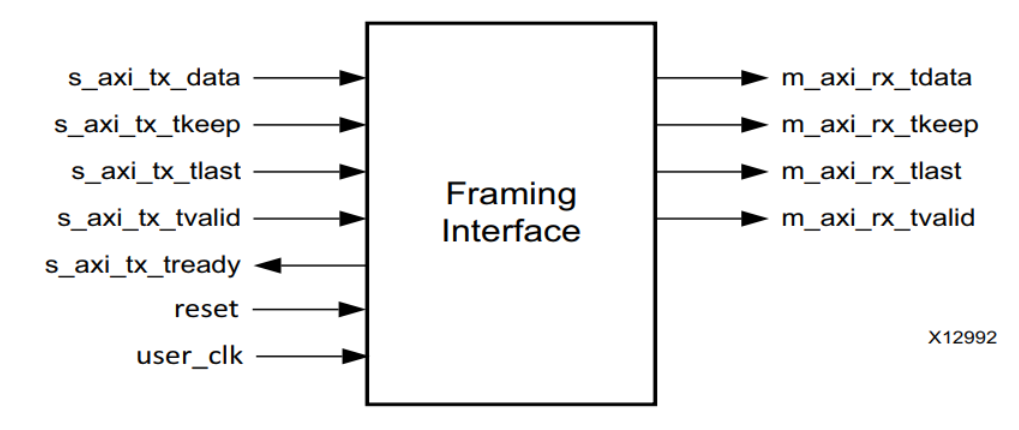
To transmit data
To transmit data , The user application manipulates the control signals to cause the kernel to do the following :
- When s_axi_tx_tvalid and s_axi_tx_tready When the signal is set , from s_axi_tx_tdata The user interface on the bus gets the data .
- adopt Aurora 8B/10B Channel serialized data in the channel .
- Use s_axi_tx_tvalid Signal transmission data . User applications can be set low s_axi_tx_tvalid To insert free... On the line ( To introduce a pause or pause ).
- Pause data ( I.e. insert free )(s_axi_tx_tvalid Invalid ).
When the kernel receives data , It does the following :
- Detect and discard control bytes ( Free 、 Clock compensation 、 The passage begins PDU (SCP)、 Channel end protocol data unit (ECPDU) and PAD.
- Assert framing signal (m_axi_rx_tlast) And specify the number of valid bytes in the last data beat (m_axi_rx_tkeep).
- Recover data from the channel .
- By setting m_axi_rx_tvalid The signal , Splice data is passed to m_axi_rx_tdata User interface on the bus .
Aurora 8B/10B The kernel is only in s_axi_tx_tready and s_axi_tx_tvalid Equal position ( high ) Sample the data .
AXI4-Stream Data is only valid when framing . Data outside the frame is ignored .
To start a frame , Please place the first word of the data in s_axi_tx_tdata Assert when on port s_axi_tx_tvalid.
To end a frame , Please put the last word in the data ( Or some words ) be located s_axi_tx_tdata Assert when on port s_axi_tx_tlast, And use s_axi_tx_tkeep Specify the number of valid bytes in the last data beat .
For single word long or shorter frames ,s_axi_tx_tvalid and s_axi_tx_tlast Be asserted at the same time .
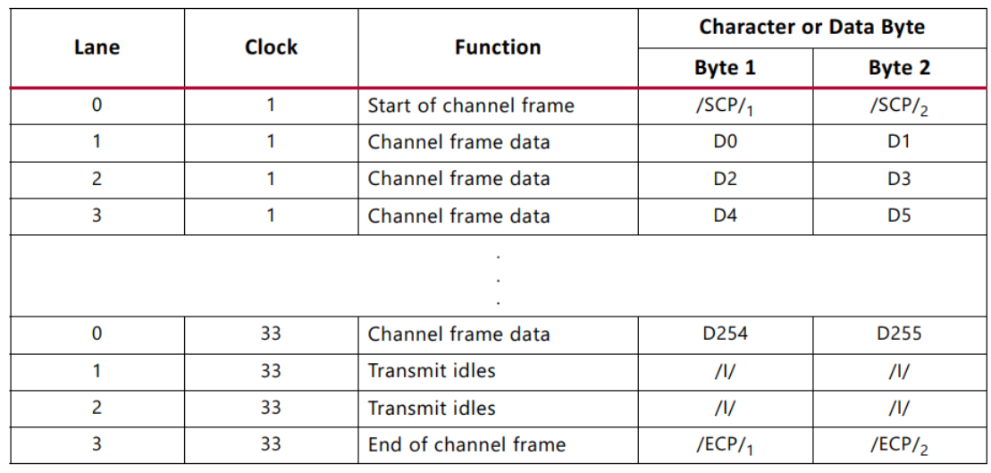
Aurora 8B/10B frame
TX The sub module will pass TX Each user frame received by the interface is converted to Aurora 8B/10B frame . Frame start (SOF) By adding... At the beginning of the frame 2 byte SCP Code group to indicate . End of the frame (EOF) By adding a... At the end of the frame 2 Byte channel end protocol (ECP) Code group to indicate . As long as the data is not available , Will insert a free code group . The code group is 8B/10B Code byte pair , All data is sent as a code group , Therefore, a user frame with odd bytes is appended to the end of the frame with a PAD To fill the final code group . The following table shows a typical... With an even number of data bytes Aurora 8B/10B frame .

length
User application through manipulation s_axi_tx_tvalid and s_axi_tx_tlast Signal to control channel frame length . Aurora 8B/10B The kernel starts with a frame and ends with a frame /SCP/ and /ECP/ To respond .
Transmission example
Simple data transfer
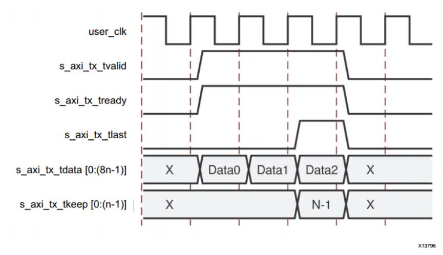
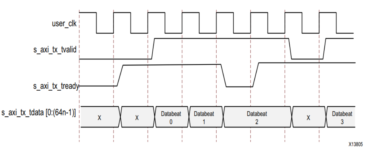
The figure below shows the n Byte wide AXI4-Stream Example of simple data transmission on the interface .

under these circumstances , The amount of data sent is 3n byte , So three data beats are needed . s_axi_tx_tready Set up , Express AXI4-Stream The interface is ready to transmit data .
User application in front n Set during bytes s_axi_tx_tvalid To start data transfer . /SCP/ The ordered set is placed on the first two bytes of the channel , To indicate the beginning of the frame . And then n–2 Data bytes are placed on the channel . because /SCP/ Offset required , The last two bytes in each data beat are always delayed by one cycle , And transmit on the first two bytes of the next beat of the channel .
To end the data transfer , User application in s_axi_tx_tkeep Set on bus s_axi_tx_tlast、 The last data byte and the appropriate value . In this example ,s_axi_tx_tkeep Set to... In the waveform N, To indicate that all bytes are valid in the last data beat . When s_axi_tx_tlast When set ,s_axi_tx_tready It is set low in the next clock cycle , The kernel uses gaps in the data stream to send the final offset data bytes and /ECP/ Ordered set , Indicates the end of the frame . s_axi_tx_tready Reset at the next cycle to allow data transmission to continue .
Use populated data transfer
The following figure shows a... That needs to be filled (3n–1) Example of byte data transmission .
Aurora 8B/10B The kernel adds padding characters to frames with odd bytes according to the protocol requirements . transmission 3n–1 Two complete data bytes are required n Byte data word and a partial data word . In this example ,s_axi_tx_tkeep Set to N–1 To indicate... In the last data word n–1 Valid bytes .
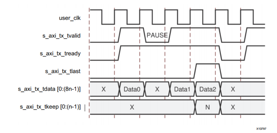
Data transmission with pause
The following figure shows how the user interface pauses data transmission during frame transmission . In this example , User application in front n After bytes, set it low s_axi_tx_tvalid Pause data flow , And change to transmission idle . The pause continues until s_axi_tx_tvalid Cancelled assertion .
Data transmission with clock compensation
Aurora 8B/10B The kernel will automatically interrupt data transmission when sending clock compensation sequence . Clock compensation sequence every 10,000 Bytes are applied to each channel 12 The cost of one byte . The image below shows Aurora 8B/10B How the kernel pauses data transmission during a clock compensation sequence .

Because every channel every 10,000 Bytes need clock compensation ( Per channel 2 Byte design requires 5,000 A clock ; Per channel 4 Byte design requires 2,500 A clock ), So you can't transfer data continuously , Can not receive data continuously . During clock compensation , Data transmission is suspended for six or three clock cycles .
receive data
RX The sub module has no built-in elastic buffer for user data . therefore ,RX AXI4-Stream There's nothing on the interface m_axi_rx_tready The signal . User application control from Aurora 8B/10B The only way to stream data from a channel is to use IP One of the optional flow control functions .
m_axi_rx_tvalid Signals from Aurora 8B/10B The first word of each frame of the kernel is set at the same time .m_axi_rx_tlast Set at the same time as the last word or part of the word in each frame . m_axi_rx_tkeep The port indicates the number of valid bytes in the last word of each frame .m_axi_rx_tkeep The signal is only in m_axi_rx_tlast Valid when set .
Aurora 8B/10B The kernel can cancel assertions at any time m_axi_rx_tvalid, Even during a frame . Even if the frame was originally transmitted without pausing , The kernel is occasionally set low m_axi_rx_tvalid. These pauses are the result of the frame character decoding and left alignment process .
The figure below shows a 3n Example of byte receiving data being suspended and interrupted .

The data is shown in m_axi_rx_tdata On the bus . At present n When bytes are placed on the bus ,m_axi_rx_tvalid Is set to indicate that the data is ready for use by the user application . The kernel will... In the clock cycle after the first data beat m_axi_rx_tvalid Buy low , To indicate that the data flow is paused . After suspension , Kernel Set m_axi_rx_tvalid And continue in m_axi_rx_tdata Assemble the remaining data on the bus . At the end of the frame , Kernel assertion m_axi_rx_tlast. The kernel also calculates m_axi_rx_tkeep The value of the bus , It is presented to the user application according to the total number of valid bytes in the last word of the frame .
Framing efficiency
There are two factors that affect Aurora 8B/10B The framing efficiency of the kernel :
Frame size .
The width of the data path .
CC Sequence ( Every time 10,000 Bytes are used on each channel 12 Bytes ) Consume about 0.12% Total channel bandwidth .
Aurora 8B/10B All bytes in the kernel are sent in a two byte code group . With even bytes Aurora 8B/10B Frames have a four byte overhead , Two bytes for SCP( Frame start ) And two bytes for ECP( End of the frame ). Having odd bytes Aurora 8B/10B The frame has 5 The cost of one byte 、4 A framing cost of bytes and an additional byte for filling bytes .
IP The frame delimiter is transmitted only in a specific channel of the channel . SCP Only on the far left ( above all ) In the channel of , and ECP Only on the far right ( least important ) In the channel of . In the last code group with data and ECP Any space in the channel between code groups is filled with free . The result is a reduction in the resource cost of the design , But at the cost of minimal additional throughput costs . Even though SCP and ECP Can be optimized for additional throughput , However, the single frame per cycle limit imposed by the user interface will make this improvement unavailable in most cases .
Use the formula shown in the formula to calculate any number of channels 、 Design efficiency of any interface width and any number of bytes of frames . The formula includes the cost of clock compensation .

among :
- E = Appoint PDU The average efficiency of .
- n = Number of user data bytes .
- 12n/9988 = Clock correction overhead .
- 4 = SCP + ECP expenses .
- 0.5 = Average PAD expenses .
- IDLE = IDLE expenses = ( w/2) – 1.
- w = Interface width .
surface 2-4 According to the formula 2-1 Calculated examples . It shows 8 byte 、4 The efficiency of the channel , It also shows that the efficiency increases with the increase of channel frame length .

surface 2-5 Shows the transmission through four channels 256 Byte frame data 8 byte 4 The cost of the channel . Due to the start and end characters and the idle time required to fill the channel , The generated data unit is 264 Byte length . This is equivalent to the transmitter overhead 3.03%. Besides , Every time 10,000 Bytes occur on each channel 12 Byte clock compensation sequence , This adds a small amount of overhead . The receiver can handle a slightly more efficient stream of data , Because it doesn't need any idle mode .
surface 2-6 Shows s_axi_tx_tkeep Cost per value of . stay Vivado Choose from Little Endian Option ,s_axi_tx_tkeep Bit order from MSB Change to LSB.

Stream interface
The following shows a configuration with a streaming user interface Aurora 8B/10B Kernel example .

Stream interface port
USER_DATA_S_AXI_TX
| name | Direction | Time domain | describe |
|---|---|---|---|
| s_axi_tx_tdata[0:(8n–1)] or s_axi_tx_tdata[(8n–1):0] | Input | user_clk | Outgoing data . As the number of lanes x Lane width . n Is the number of bytes calculated . |
| s_axi_tx_tready | Output | user_clk | Asserts when the signal from the source is accepted and the output data is ready for transmission . |
| s_axi_tx_tvalid | Input | user_clk | When it comes out AXI4-Stream Set when the signal or the signal from the source is valid . |
USER_DATA_M_AXI_RX
| name | Direction | Time domain | describe |
|---|---|---|---|
| m_axi_rx_tdata[0:8(n–1)] or m_axi_rx_tdata[8(n–1):0] | Output | user_clk | Incoming data from the channel ( Ascending bit order ). |
| m_axi_rx_tvalid | Output | user_clk | When it comes from Aurora 8B/10B Set when the outgoing data and control signals of the kernel or the data and control signals are valid . |
Sending and receiving data
Stream interface allows Aurora 8B/10B The passage serves as a conduit . After the initialization , Channels are always available for writing , Except when sending clock compensation sequence . The core data transmission conforms to AXI4-Stream agreement .
When s_axi_tx_tvalid When set low , There will be a gap between words and keep the gap , Unless the clock compensation sequence is being transmitted . When the data arrives Aurora 8B/10B The tunnel RX Side time , It will appear in m_axi_rx_tdata On the bus , also m_axi_rx_tvalid To be placed . The data must be read immediately , Otherwise it will be lost . If this is unacceptable , The buffer must be connected to RX Interface to save data , Until it can be used .
Transmission example
TX Streaming data
The following figure shows a typical example of streaming data .
Aurora 8B/10B The kernel is set by s_axi_tx_tready To indicate that it is ready to transmit data . After a cycle , User logic pass set s_axi_tx_tdata Bus and s_axi_tx_tvalid Signal to indicate that it is ready to transmit data . Because both ready signals are now set , So the data D0 From user logic to Aurora 8B/10B kernel . data D1 Transmit in the next clock cycle . In this example ,Aurora 8B/10B The kernel sends its ready signal s_axi_tx_tready Buy low , Until the next clock cycle is set again s_axi_tx_tready Signal before transmitting data . Then the user logic will... In the next clock cycle s_axi_tx_tvalid Buy low , Data is not transmitted until both ready signals are set .
RX Streaming data
The following figure shows the receiving end of data transmission .

flow control
This section describes how to use Aurora 8B/10B flow control . There are two optional flow control interfaces on the kernel that use the frame interface . Local flow control (NFC) Adjust the data transmission rate at the receiving end of the full duplex channel . User flow control (UFC) Provide high priority messages for control operations .
User flow control interface
UFC The interface is generating the kernel and enabling UFC Created when , Here's the picture .
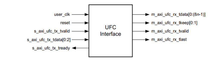
TX On the side UFC s_axi_ufc_tx_tvalid and s_axi_ufc_tx_tready Port boot UFC news ,3 position s_axi_ufc_tx_tdata The port specifies the length of the message . Assertion s_axi_ufc_tx_tready after , Can be UFC The message is provided to the data port .
UFC Interface RX The end consists of a group AXI4-Stream Port composition , Allows you to UFC Messages are read as frames simplex The interface required to send data in the supported direction .
UFC I/O Port description
UFC_S_AXIS_TX
| name | Direction | Time domain | describe |
|---|---|---|---|
| s_axi_ufc_tx_tvalid | Input | user_clk | Assert that the request is sent to the cooperative channel UFC news . Must be maintained until s_axi_ufc_tx_tready Be asserted . Unless you are ready to send the whole UFC news , Otherwise, do not assert this signal ; UFC The message cannot be interrupted after it starts . |
| s_axi_ufc_tx_tdata[0:2] or s_axi_ufc_tx_tdata[2:0] | Input | user_clk | Designated to be sent UFC The size of the message . SIZE Code is a code between 0 and 7 Between the value of the . |
| s_axi_ufc_tx_tready | Output | user_clk | When Aurora 8B/10B The kernel is ready to read UFC The content of the message is set . stay s_axi_ufc_tx_tready Within the period after the signal is set ,s_axi_tx_tdata The data on the port is treated as UFC data . s_axi_tx_tdata Data continues to be used to populate UFC news , Until enough cycles have passed to send a complete message . UFC Unused bytes in the loop will be discarded . |
UFC_M_AXIS_RX
| name | Direction | Time domain | describe |
|---|---|---|---|
| m_axi_ufc_rx_tdata[0:(8n–1)] or m_axi_ufc_rx_tdata[(8n–1):0] | Output | user_clk | Incoming from channel UFC The message data ( Maximum n = 16 Bytes ). |
| m_axi_ufc_rx_tvalid | Output | user_clk | When m_axi_ufc_rx_tdata Set when the value on the port is valid . |
| m_axi_ufc_rx_tlast | Output | user_clk | It means incoming UFC The end of the message . |
| m_axi_ufc_rx_tkeep[0:(n–1)] or m_axi_ufc_rx_tkeep[(n–1):0] | Output | user_clk | Specified in the UFC The last word of the message m_axi_ufc_rx_tdata Number of valid data bytes displayed on the port . Only when the m_axi_ufc_rx_tlast Valid when set (n = Maximum 16 byte ). |
transmission UFC news
UFC Messages can be carried from 2 To 16 Even data bytes of . User applications are driven by s_axi_ufc_tx_tdata On port SIZE Code to specify the length of the message . The following table Shows UFC The legality of the message SIZE Code value .
| SIZE Field Contents | UFC Message Size |
|---|---|
| 000 | 2 bytes |
| 001 | 4 bytes |
| 010 | 6 bytes |
| 011 | 8 bytes |
| 100 | 10 bytes |
| 101 | 12 bytes |
| 110 | 14 bytes |
| 111 | 16 bytes |
To send UFC news , The user application is using the required SIZE Code driven s_axi_ufc_tx_tdata Port when asserted s_axi_ufc_tx_tvalid. s_axi_ufc_tx_tvalid The signal must be maintained until Aurora 8B/10B Kernel Set s_axi_ufc_tx_tready The signal .UFC The data of the message must be in s_axi_tx_tdata On port , from s_axi_ufc_tx_tready The first cycle after setting starts . When s_axi_tx_tdata The port is used for UFC Data time , The kernel will s_axi_tx_tready Buy low . Only after the current UFC A request can only be sent UFC request ; IP Back to back... May not be supported UFC request .
The following figure shows an example of a TX_D Switch from sending regular data to UFC Data circuit .

surface 2-9 Shows the basis for AXI4-Stream The width of the data interface is transmitted in different sizes UFC Number of cycles required for the message . Before all message data is available , Should not start UFC news . Unlike regular data ,UFC Message in s_axi_ufc_tx_tready Cannot be interrupted after being asserted , Until now UFC Message complete .

Transmission single cycle UFC news
Transmission single cycle UFC The message process is shown in the following figure . under these circumstances , stay 4 Send on byte interface 4 Byte message .s_axi_ufc_tx_tready The signal is set low in two cycles . Aurora 8B/10B The kernel uses this gap in the data stream to transmit UFC Header and message data .

Transmit multiple cycles UFC news
Two transmission cycles UFC The message process is shown in the following figure . under these circumstances , The user application uses 2 Byte interface send 4 Byte message .s_axi_tx_tready Assert three cycles : One cycle is used in s_axi_ufc_tx_tready Sent during the cycle UFC header , Two cycles are used for UFC data .

receive UFC news
When Aurora 8B/10B The kernel received UFC When the news , It will be through dedicated UFC AXI4-Stream Interface to pass data to user applications . The data is presented in m_axi_ufc_rx_tdata On port ; m_axi_ufc_rx_tvalid Indicates the beginning of message data ,m_axi_ufc_rx_tlast End of the said . m_axi_ufc_rx_tkeep Used to display messages in the last cycle m_axi_ufc_rx_tdata Number of significant bytes on .
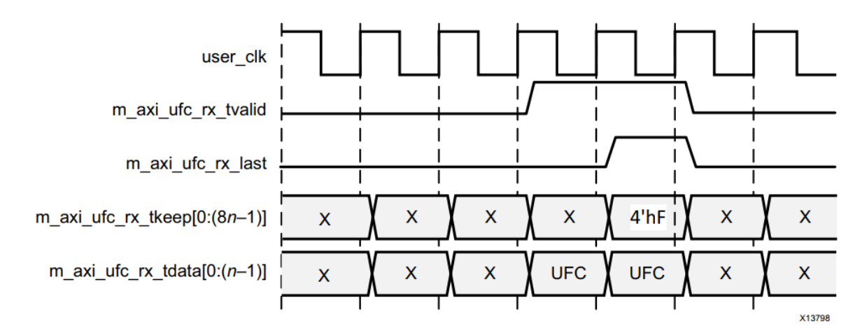
Receive single cycle UFC news
The following figure shows the with 4 Byte data interface Aurora 8B/10B Kernel receive 4 byte UFC news . The kernel is set by m_axi_ufc_rx_tvalid and m_axi_ufc_rx_tlast To provide this data to the user application to indicate a single periodic frame .m_axi_ufc_rx_tkeep Set to 4’hF, Indicates that only the four most significant bytes of the interface are valid .

Receive multiple cycles UFC news
The following figure shows the with 4 Byte interface Aurora 8B/10B Kernel receive 8 Byte message . The generated frame is two cycles long ,m_axi_ufc_rx_tkeep Set the second cycle to 4’hF, All four bytes of data are valid .
Native Flow Control
Aurora 8B/10B Protocol includes local flow control (NFC) Interface , As shown in the figure below .

This interface allows the receiver to control the rate of receiving data by specifying the number of idle data ticks that must be put into the data stream . It is even possible to send only idle... Temporarily by requesting the sender (XOFF) To shut down the data flow completely .NFC Usually used to prevent FIFO Spillage .
Native flow control interface
NFC The interface is generating the kernel and enabling NFC Options . This interface includes for sending NFC Requests for information (s_axi_nfc_tx_tvalid) And confirmation (s_axi_nfc_tx_tready) port , And... For specifying the number of idle cycles requested 4 position s_axi_nfc_tx_tdata port .
The following table lists the full duplex only Aurora 8B/10B Available in the kernel NFC Interface port .
NFC I/O Ports
NFC_S_AXIS_TX
| Name | Direction | Clock Domain | Description |
|---|---|---|---|
| s_axi_nfc_tx_tready | Output | user_clk | When the core accepts NFC Set on request . |
| s_axi_nfc_tx_tdata[0:3] or s_axi_nfc_tx_tdata[3:0] | Input | user_clk | Indicates that the connection channel received NFC Message must be sent PAUSE Free number . Must be maintained until s_axi_nfc_tx_tready Be asserted . |
| s_axi_nfc_tx_tvalid | Input | user_clk | Assert that the request is sent to the connection channel NFC news . Must be maintained until s_axi_nfc_tx_tready Be asserted . |
NFC_M_AXIS_RX
| Name | Direction | Clock Domain | Description |
|---|---|---|---|
| m_axi_nfc_tx_tvalid | Output | user_clk | Indicates receipt of... From a partner NFC news . |
| m_axi_nfc_tx_tdata[0:3] or m_axi_nfc_tx_tdata[3:0] | Output | user_clk | Indicates the received NFC News PAUSE value . You should use m_axi_nfc_tx_tvalid Sample the port . |
The following table shows the local flow control (NFC) Code for . These values are in the big end format [0:3] Bit and small end format [3:0] Bit up drive .
| s_axi_nfc_tx_tdata | Idle Cycles Requested |
|---|---|
| 0000 | 0 (XON) |
| 0001 | 2 |
| 0010 | 4 |
| 0011 | 8 |
| 0100 | 16 |
| 0101 | 32 |
| 0110 | 64 |
| 0111 | 128 |
| 1000 | 256 |
| 1001 to 1110 | Reserved |
| 1111 | Infinite (XOFF) |
The user application asserts s_axi_nfc_tx_tvalid And will NFC Code writing s_axi_nfc_tx_tdata. NFC The code indicates that the channel partner should TX The minimum number of idle cycles inserted in the data stream . User applications must remain s_axi_nfc_tx_tvalid and s_axi_nfc_tx_tdata, until s_axi_nfc_tx_tready To be placed . Aurora 8B/10B The kernel is sending NFC Unable to transmit data while message .s_axi_tx_tready Always in s_axi_nfc_tx_tready The period after the assertion is cancelled .
send out NFC Message example
The following figure shows the user application sending... To the channel partner NFC Example of transmission timing for message .s_axi_nfc_tx_tready The signal is set low for one cycle ( hypothesis n At least for 2) To place NFC Create gaps in the message's data flow .
 Receive inserted NFC Examples of idle messages
The following figure shows the received NFC When the news TX Examples of signals on the user interface . under these circumstances ,NFC The code of the message is 0001, Request two idle data ticks . The core is set low on the user interface s_axi_tx_tready, Until enough free time is sent to satisfy the request . In this example , The kernel is immediately NFC Run in mode , Where... Is inserted immediately NFC Free . Aurora 8B/10B The kernel can also run in completion mode , among NFC Idle inserts only between frames . If the completion mode core receives... When transmitting frames NFC news , It will cancel the assertion s_axi_tx_tready To complete the transmission frame before inserting idle .

state 、 Control and transceiver interface
Aurora 8B/10B The state and control ports of the kernel allow applications to monitor channels and use the built-in capabilities of transceivers . This section provides status and control interfaces 、 Transceiver serial I/O Interface and side band initialization port chart and port description for simplex module .
Status and control ports
The following table describes Aurora 8B/10B The function of each state and control port of the kernel .
| Name | Direction | Clock Domain | Description |
|---|---|---|---|
| channel_up/ tx_channel_up/ rx_channel_up | Output | user_clk | When Aurora 8B/10B Set when channel initialization is complete and the channel is ready for data transmission . tx_channel_up and rx_channel_up Only applicable to their respective simplex cores . |
| lane_up[0:m–1]/ tx_lane_up[0:m–1]/ rx_lane_up[0:m–1] | Output | user_clk | Set each channel after successful channel initialization , Each bit represents a channel . tx_lane_up[0:(m–1)] and rx_lane_up[0:(m–1)] Only applicable to their respective simplex cores .m It's the number of transceivers . |
| frame_err | Output | user_clk | Channel frame detected / Protocol error . The port is asserted as a single clock . Not applicable to simplex TX kernel . |
| hard_err/ tx_hard_err/ rx_hard_err | Output | user_clk | Hard error detected ( stay Aurora 8B/10B Valid until the kernel is reset ). tx_hard_err and rx_hard_err Only applicable to their respective simplex cores . |
| soft_err | Output | user_clk | A soft error was detected in the incoming serial stream . In simplex TX Not available on the kernel . |
| reset/ tx_system_reset/ rx_system_reset | Input | async | Reset Aurora 8B/10B kernel ( High active ). The signal must be asserted for at least six user_clk cycle . tx_system_reset and rx_system_reset Only applicable to their respective simplex cores . |
| gt_reset | Input | async | The reset signal of the transceiver is connected to the top layer through the de dither . gt_reset The port shall be set when the module is powered on for the first time . This systematically resets all physical coding sublayers of the transceiver (PCS) And physical media attachments (PMA) Child components . This signal uses init_clk_in De jitter , And must be within six init_clk_in Period built-in bit . |
| link_reset_out | Output | init_clk | If the hot plug count expires , Then the drive is high level . |
| init_clk_in | Input | NA | init_clk_in Port is required , Because when gt_reset Setting time user_clk stop it . The suggestion is init_clk_in The selected frequency is lower than GT Reference clock input frequency . |
| tx_aligned | Input | user_clk | When RX Set when the channel completes the channel initialization of all channels . Usually connected to rx_aligned. |
| tx_bonded | Input | user_clk | When RX Set when the channel completes the channel binding . Single channel channels do not require . Usually connected to rx_bonded. |
| tx_verify | Input | user_clk | When RX Set when the channel completes verification . Usually connected to rx_verify. |
| tx_reset | Input | user_clk | because RX Set when the channel needs to be reset due to its initialization state . The signal must be connected to user_clk Sync , And must be in at least one user_clk Set in cycle . Usually connected to rx_reset. |
| rx_aligned | Output | user_clk | When RX Set when the module completes channel initialization . Usually connected to tx_aligned. |
| rx_bonded | Output | user_clk | When RX Set when the module completes channel binding . Not used for single channel . Usually connected to tx_bonded. |
| rx_verify | Output | user_clk | When RX Set when the module completes verification . Usually connected to tx_verify. |
| rx_reset | Output | user_clk | When RX Module needs TX Module reinitialization is set during initialization . Usually connected to tx_reset. |
Full duplex kernel
Full duplex status and control ports
Full duplex kernel provides TX and RX Aurora 8B/10B Channel connection . The following figure shows full duplex Aurora 8B/10B The state and control interface of the kernel .

Error status signal
Equipment problems and channel noise may cause Aurora 8B/10B An error occurred during channel operation . 8B/10B Coding allows Aurora 8B/10B The kernel detects all unit errors and most multi bit errors that occur in the channel , And set at each cycle soft_err.
TX Simplex kernel does not include soft_err port . Unless there is a problem with the equipment , Otherwise, it is assumed that all transmitted data is correct at the time of transmission . The kernel also monitors each transceiver for hardware errors , For example, buffer overflow / Underflow and lock loss , And assert that hard_err The signal . Use rx_hard_err Signal reporting in simplex kernel RX Hard end error . Catastrophic hardware errors can also be expressed as the outbreak of software errors . The kernel using Aurora 8B/10B Protocol specification Describes a leaky bucket algorithm to detect a large number of soft errors that occur in a short time , And assert that hard_err or rx_hard_err The signal .
Whenever a hard error is detected , The kernel will automatically reset and try to reinitialize . This allows the channel to be reinitialized and re established as soon as the hardware problem that caused the hard error is resolved . Unless enough soft errors occur in a short time , Otherwise, it will not cause reset .
have AXI4-Stream Data interface Aurora 8B/10B The kernel can also detect Aurora 8B/10B Frame and assert frame_err The signal . Frame errors can be frames without data 、 Continuous frame start symbol and continuous frame end symbol . This signal is not applicable to simplex TX kernel . When available , This signal is usually close to soft_err Be asserted when asserted , Soft error is the main cause of frame error .
The following table summarizes Aurora 8B/10B Error conditions that the kernel can detect and error signals used to alert the user application .

Full duplex initialization
The full duplex core is powered on 、 Automatic initialization after reset or hard error , And implement Aurora 8B/10B Initializer , Until the channel is ready for use . lane_up The bus indicates which of the channels have completed the channel initialization process . This signal can be used to help debug equipment problems in multi-channel channels .
Assertions are made only after the kernel has completed the entire initialization process channel_up. In a statement channel_up Before ,Aurora 8B/10B The kernel cannot receive data . Only the... On the user interface should be used m_axi_rx_tvalid Signals to limit incoming data .channel_up Can be reversed and used to reset the drive full duplex channel TX Side modules , Because in channel_up Before transmission . If the user application module needs to be reset before data reception , You can reverse and use one of the lane_up The signal . Until all the lane_up Data can only be received after the signal is set .
Simplex kernel
Simplex TX Status and control ports
Simplex TX The kernel allows user applications to transfer data to simplex RX kernel . They didn't RX Connect . The following figure shows simplex TX The state and control interface of the kernel .

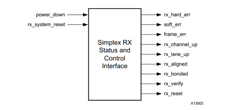
Simplex RX Status and control ports
Simplex RX The kernel allows user applications to simplex TX The kernel receives data . The following figure shows simplex RX The state and control interface of the kernel .
Simplex initialization
Simplex The kernel does not depend on the Aurora 8B/10B The signal of the channel is initialized . contrary , Single aisle TX and RX The side transmits its initialization status through a group of sideband initialization signals : alignment 、 binding 、 Verification and reset ; One set is used with TX_ Prefixed TX Side , One set is used with RX_ Prefixed RX Side . The binding port is only used for multi-channel kernel . There are two methods of initializing simplex module with unilateral initialization signal :
- Take information from RX The sideband initialization port is sent to TX Sideband initialization port .
- Use a timed initialization interval independent of RX Sideband initialization port drive TX Sideband initialization port .
Use the reverse channel
The reverse channel is in RX and TX The safest way to initialize and maintain a simplex channel without a channel between . The reverse channel simply passes the message to TX Side , To indicate which sideband initialization signal is asserted when the signal changes . Included in example_design With simplex in the directory Aurora 8B/10B The sample design of the kernel shows a simple side channel , This channel uses three or four... On the device I/O Pin .
Use timer
If reverse channel is not possible , The serial channel can be driven by using a set of timers TX Simplex initialization to initialize . Timers must be carefully designed to meet the needs of the system , Because the average initialization time depends on many channel specific conditions , For example, clock speed 、 Channel delay 、 Offset and noise between channels .
C_ALIGNED_TIMER、C_BONDED_TIMER and C_VERIFY_TIMER Are used separately to assert tx_aligned、tx_bonded and tx_verify Signal timer . These timers are obtained from the functional simulation of extreme cases and used in <component name>_core The worst case value implemented in the module .
Aurora 8B/10B Some of the initialization logic in the module uses a watchdog timer to prevent deadlock . These watchdog timers are used for channel RX Side , It could interfere with TX Initialize the normal operation of the timer . If RX Simplex module from alignment 、 Binding or validation becomes reset , Please make sure this is not because TX Logic spends too much time in one of these States . If you need a very long timer to meet the needs of the system , The watchdog timer can be adjusted by editing the module . in the majority of cases , This is not necessary , This is not recommended .
Aurora 8B/10B Channels are usually reinitialized only in the event of a failure . When no reverse channel is available , For most mistakes , Event triggered reinitialization is not possible , Because usually ,RX Side detected fault , And the conditions must be determined by TX Side treatment . The solution is to let the timer drive TX The simplex module is periodically reinitialized . If there is a catastrophic mistake , The channel will be reset and run again after the next reinitialization cycle . The system designer should balance the average time required for reinitialization with the maximum time that the system can tolerate an inoperative channel , To determine the optimal reinitialization cycle of the system .
Transceiver interface
The interface includes the serial of transceiver I/O port , And control and status .
| Name | Direction | Clock Domain | Description |
|---|---|---|---|
| rxp[0:m–1] | Input | RX Serial Clock | Positive differential serial data input pin . |
| rxn[0:m–1] | Input | RX Serial Clock | Negative differential serial data input pin . |
| txp[0:m–1] | Output | TX Serial Clock | Positive differential serial data input pin . |
| txn[0:m–1] | Output | TX Serial Clock | Negative differential serial data input pin . |
| power_down | Input | user_clk | Drive the power down input of the transceiver . For more information , Refer to the applicable transceiver User Guide . |
| loopback[2:0] | Input | user_clk | loopback[2:0] The port selects between normal operation of the transceiver and different loopback modes . |
| tx_resetdone_out | Output | user_clk | Transceiver's TXRESETDONE The signal . |
| rx_resetdone_out | Output | user_clk | Transceiver's RXRESETDONE The signal . |
| tx_lock | Output | user_clk | Indicates the incoming serial transceiver refclk Phase locked loop by transceiver (PLL) lock . |

Clock interface
The clock interface has a port for the transceiver reference clock , as well as Aurora 8B/10B Parallel clock shared by kernel and application logic . The following table describes Aurora 8B/10B Kernel clock port .
Clock Ports for Aurora 8B/10B Core
| Clock Ports | Direction | Description |
|---|---|---|
| pll_not_locked | Input | If you use PLL by Aurora 8B/10B The kernel generates the clock , be pll_not_locked The signal shall be connected to PLL The reverse phase of the lock signal . If PLL Not used for Aurora 8B/10B The kernel generates clockticks , Please put pll_not_locked Grounding . |
| user_clk | Input | from Aurora 8B/10B A parallel clock shared by the kernel and user applications . user_clk and sync_clk yes tx_out_clk Driven PLL or BUFG Output . These clocks can be generated in <component name>_clock_module Found in file .user_clk As a transceiver txusrclk2 Input . |
| sync_clk | Input | The parallel clock used by the internal synchronization logic of the transceiver . sync_clk As a transceiver txusrclk Input . |
| gt_refclk | Input | adopt IBUFDS_GTE Fed gt_refclk (clkp/clkn) po Transceiver reference clock . |
| gt0_pll0outclk_in/ gt1_pll0outclk_in | Input | This port should be connected to GTPE2_COMMON Generated PLL0OUTCLK/PLL1OUTCLK Clock output . This port is internally connected to GTPE2_CHANNEL On the primitive PLL0CLK/PLL1CLK port . |
| gt0_pll0outrefclk_in/ gt0_pll1outrefclk_in | Input | This port should be connected to GTPE2_COMMON Generated PLL0OUTREFCLK/PLL1OUTREFCLK Clock output . This port is internally connected to GTPE2_CHANNEL On the primitive PLL0REFCLK/PLL1REFCLK port . |
| quad1_common_lock_in | Input | GTPE2_COMMON PLL Lock the input port . |
The following table provides detailed information about port changes caused by selecting the shared logic option .
| Name | Direction | Description | Remarks |
|---|---|---|---|
| gt_refclk1_p gt_refclk1_n | Input | Transceiver reference clock 1 | Enable when sharing logic in the kernel is selected . Single ended GT REFCLK Options provide single ended gtrefclk1 Input . |
| gt_refclk2_p gt_refclk2_n | Input | Transceiver reference clock 2 | Enable when sharing logic in the kernel is selected . Single ended GT REFCLK Options provide single ended gtrefclk2 Input . |
| gt_refclk1_out | Output | Transceiver reference clock 1 Of IBUFDS_GTE2 Output | Enable when sharing logic in the kernel is selected . Not applicable to single ended GT REFCLK Options . |
| gt_refclk2_out | Output | Transceiver reference clock 2 Of IBUFDS_GTE2 Output | Enable when sharing logic in the kernel is selected . Not applicable to single ended GT REFCLK Options . |
| user_clk_out | Output | Aurora 8B/10B Parallel clock shared by kernel | Enable when sharing logic in the kernel is selected |
| sync_clk_out | Output | be used for A7 device GTP Transceiver design txusrclk | Enable when sharing logic in the kernel is selected |
| sys_reset_out | Output | De dither output for reset | Enable when sharing logic in the kernel is selected |
| gt_reset_out | Output | gt_reset De dither output | Enable when sharing logic in the kernel is selected |
| init_clk_p init_clk_n | Input | A free running system / Board clock | Enable when sharing logic in the kernel is selected . Single Ended INIT CLK Options provide single ended init_clk Input . |
| init_clk_out | Output | System clock differential buffer output | Enable when sharing logic in the kernel is selected . Not applicable to single ended INIT CLK Options . |
| gt0_pll0refclklost_out gt1_pll0refclklost_out | Output | Express GTPE2_COMMON Of refclklost port | Enable when sharing logic in the kernel is selected . |
| quad1_common_lock_out quad2_common_lock_out | Output | Express GTPE2_COMMON Of PLL Lock implemented | Enable when sharing logic in the kernel is selected . |
| gt0_pll0outclk_out gt0_pll1outclk_out gt0_pll0outrefclk_out gt0_pll1outrefclk_out gt1_pll0outclk_out gt1_pll1outclk_out gt1_pll0outrefclk_out gt1_pll1outrefclk_out | Output | GTPE2_COMMON Generated clock output | Enable when sharing logic in the kernel is selected . |
| gt< quad>_qplllock_out | Output | Express GTXE2_COMMON/GTHE2_COMMON Of PLL Lock implemented | Enable when sharing logic in the kernel is selected . |
| gt< quad>_qpllrefclklost _out | Output | instructions GTXE2_COMMON/GTHE2_COMMON The reference clock input of is missing | Enable when sharing logic in the kernel is selected . |
| gt_qpllclk_quad< quad>_out gt_qpllclk_quad< quad> _out | Output | GTXE2_COMMON/GTHE2_COMMON Generated clock output | Enable when sharing logic in the kernel is selected . |
| gt_qpllrefclk_quad< quad>_ out | Output | from GTXE2_COMMON/GTHE2_COMMON Generated four way PLL (QPLL) Reference clock output | Enable when sharing logic in the kernel is selected . |
| gt< quad>_qplllock_in | Input | Express GTXE2_COMMON/GTHE2_COMMON Of PLL Lock implemented | Enable when selecting shared logic in the sample design . |
| gt< quad>_qpllrefclklost_in | Input | Express GTXE2_COMMON/GTHE2_COMMON The reference clock input of is missing | Enable when selecting shared logic in the sample design . |
| gt_qpllclk_quad< quad>_in | Input | GTXE2_COMMON/GTHE2_C OMMON Generated clock output | Enable when selecting shared logic in the sample design . |
| gt_qpllrefclk_quad< quad>_ in | Input | from GTXE2_COMMON/GTHE2_COMMON Generated QPLL Reference clock output | Enable when selecting shared logic in the sample design . |
| gt_qpllreset_out | Output | Grounding | Enable when selecting shared logic in the sample design . |
| tx_out_clk | Output | Aurora 8B/10B Parallel clock shared by kernel | Enable when selecting shared logic in the sample design . |
CRC
CRC Module supply 16 Bit or 32 position CRC, For user data . The following table describes CRC Module port .
| Port Name | Direction | Domain | Description |
|---|---|---|---|
| c_valid | Output | user_clk | CRC Valid port . When set to high level , Enable pair crc_pass_fail_n Signal sampling . |
| c_pass_fail_n | Output | user_clk | When the transmitter and receiver CRC When values match ,crc_pass_fail_n The signal is set to high level during transmission and reception . crc_pass_fail_n Signals can only be associated with crc_valid Signals are sampled together . |
Generate none GT Of Aurora
This option is only available in UltraScale and UltraScale+ Available in the device . When enabled , It will generate without GT Of Aurora kernel , And move the transceiver from the kernel to the support level in the sample design . The following table provides the information for Aurora IP Outside and GT A list of ports where transceivers interact .
| Name | Direction | Clock Domain | Description |
|---|---|---|---|
| gttxresetdone_in | Input | user_clk | towards Aurora A high level valid indication indicating that the transmitter reset sequence of the transceiver primitive initiated by the reset controller help block has been completed . |
| gtrxresetdone_in | Input | user_clk | towards Aurora A high level valid indication indicating that the receiver reset sequence of the transceiver primitive initiated by the reset controller help block has been completed . |
| rxdata_in | Input | user_clk | The user interface of the transceiver channel to receive data . |
| rxnotintable_in | Input | - | Connect to UltraScale GT The guide rxctrl3_out port . |
| rxdisperr_in | Input | - | Connect to UltraScale GT The guide rxctrl1_out port . |
| rxchariscomma_in | Input | - | Connect to UltraScale GT The guide rxctrl2_out port . |
| rxcharisk_in | Input | - | Connect to UltraScale GT The guide rxctrl0_out port . |
| rxrealign_in | Input | - | Connect to UltraScale GT The guide rxbyterealign_out port . |
| rxbufferr_in | Input | - | Connect to UltraScale GT The guide rxbufstatus_out port . |
| txbuferr_in | Input | - | Connect to UltraScale GT The guide txbufstatus_out port . |
| chbonddone_in | Input | - | Connect to UltraScale GT The guide rxchanisaligned_out port . |
| txoutclk_in | Input | - | Connect to UltraScale GT The guide txoutclk_out port . |
| txlock_in | Input | - | Connect to UltraScale GT The guide cplllock_out port . |
| rxfsm_datavalid_out | Output | user_clk | Active-High Express Aurora All channels on are started . |
| rxpolarity_out | Output | user_clk | If Aurora Incoming... Detected rxdata Polarity reversal in , The high level is active This data is used as part of the polarity reversal logic , Start the link at the same time . |
| rxreset_out | Output | user_clk | from Aurora Receive channel generated reset . |
| txcharisk_out | Output | user_clk | Connected to the transceiver channel primitive TXCTRL2. |
| txdata_out | Output | user_clk | Connect to US GT User interface in the wizard , In order to transmit data through the transceiver channel . |
| gtrxreset_out | Output | user_clk | Connect to US GT Wizard Of gtwiz_reset_rx_datapath_in port . |
| enacommaalign_out | Output | user_clk | Detect aligned byte boundaries . |
| enchansync_out | Output | user_clk | Connect to US GT Wizard Of rxchanbonden_in port . |
reference
- PG046
边栏推荐
猜你喜欢

Pycharm的快捷键Button 4 Click是什么?

WordPress pseudo original tool - update website one click pseudo original publishing software

IP - 射频数据转换器 -04- API使用指南 - 系统设置相关函数
二叉排序树的基本操作

太厉害了MySQL总结的太全面了

模块 14 - 15:网络应用通信考试

Memorizing Normality to Detect Anomaly: Memory-augmented Deep Autoencoder for Unsupervised Anomaly D

You have an error in your SQL syntax; check the manual that corresponds to your MYSQL server

After the code is generated by the code generator, the copy is completed, and the module is not displayed on the web page

Attack and defense world PHP_ rce
随机推荐
【数据挖掘】期末复习 第一章
Solve the first problem of Huawei's machine test on April 20 by recursion and circulation (100 points)
判断一棵树是否为完全二叉树
After the code is generated by the code generator, the copy is completed, and the module is not displayed on the web page
Metasploit intrusion win7
Microbial ecological sequencing analysis -- CCA analysis
Leetcode刷题 ——— (4)字符串中的第一个唯一字符
Leetcode刷題 ——— (4)字符串中的第一個唯一字符
IP - RF data converter -04- API User Guide - ADC status indication function
tf.compat.v1.get_default_graph
numpy. get_ include()
高速缓存Cache(计算机组成原理笔记)
[data mining] final review Chapter 5
【数据挖掘】期末复习 第二章
C language course design (detailed explanation of clothing management system)
pyshark使用教程
tf.AUTO_REUSE作用
太厉害了MySQL总结的太全面了
Memorizing Normality to Detect Anomaly: Memory-augmented Deep Autoencoder for Unsupervised Anomaly D
Q & A: issues related to "micro build low code" billing