当前位置:网站首页>Debugging mipi-dsi screen based on stm32mp157
Debugging mipi-dsi screen based on stm32mp157
2022-06-25 07:55:00 【Talent、me】
platform :STM32MP157
The screen :mipi-dsi Interface ,1024x600
Kernel version :linux5-4
This is my first debugging mipi screen , stay 157 There are a few problems on this platform , Next, I will briefly describe my debugging experience
One 、 First configure the device tree DTB
<dc {
port {
#address-cells = <1>;
#size-cells = <0>;
ltdc_ep1_out: [email protected]1 {
reg = <1>;
remote-endpoint = <&dsi_in>;
};
};
};
&dsi {
#address-cells = <1>;
#size-cells = <0>;
status = "okay";
ports {
#address-cells = <1>;
#size-cells = <0>;
[email protected]0 {
reg = <0>;
dsi_in: endpoint {
remote-endpoint = <<dc_ep1_out>;
};
};
[email protected]1 {
reg = <1>;
dsi_out: endpoint {
remote-endpoint = <&dsi_panel_in>;
};
};
};
[email protected]0 {
compatible = "Hyb-Mipi";
reg = <0>;
enable-gpios = <&gpioc 6 GPIO_ACTIVE_HIGH>;
reset-gpios = <&gpioe 4 GPIO_ACTIVE_HIGH>;
status = "okay";
port {
dsi_panel_in: endpoint {
remote-endpoint = <&dsi_out>;
};
};
};
};
Two 、 Drive selection
stay STM32MP157 In the source code , It comes with a file named panel-simple.c Universal drive . It has been adjusted in this file before LCD The screen , Open the file to see , In fact, this file is also compatible mipi-dsi The screen of . Maybe some screens can use this file to debug , The attention is to see CONFIG_DRM_MIPI_DSI Whether this option has a choice .
static int __init panel_simple_init(void)
{

	int err;

	err = platform_driver_register(&panel_simple_platform_driver);
	if (err < 0)
		return err;

	if (IS_ENABLED(CONFIG_DRM_MIPI_DSI)) {

		err = mipi_dsi_driver_register(&panel_simple_dsi_driver);
		if (err < 0)
			return err;
	}

	return 0;
}
module_init(panel_simple_init);
The next screen I debug cannot use this file .
Find a similar driver to modify and fill
You can driver/gpu/drm/panel/ Find a driver code of other screen manufacturers in the source code directory and modify it .
Next, the driver code is modified :
First, driver and device tree adaptation
static const struct of_device_id hyb_of_match[] = {

	{
     .compatible = "Hyb-Mipi", },
	{
     /* sentinel */ }
};
MODULE_DEVICE_TABLE(of, hyb_of_match);

static struct mipi_dsi_driver hyb_driver = {

	.probe = hyb_dsi_probe,
	.remove = hyb_dsi_remove,
	.driver = {

		.name = "Hyb-Mipi",
		.of_match_table = hyb_of_match,
	},
};
Enter after successful adaptation hyb_dsi_probe function , This function interface is mainly used to obtain some parameters of the device tree settings , Configure it DSI Format .
static int hyb_dsi_probe(struct mipi_dsi_device *dsi)
{

	struct hyb *ctx;
	int ret;

	ctx = devm_kzalloc(&dsi->dev, sizeof(*ctx), GFP_KERNEL);
	if (!ctx)
		return -ENOMEM;

	mipi_dsi_set_drvdata(dsi, ctx);
	ctx->dsi = dsi;

	drm_panel_init(&ctx->panel);
	ctx->panel.dev = &dsi->dev;
	ctx->panel.funcs = &hyb_funcs;

	ctx->reset = devm_gpiod_get(&dsi->dev, "reset", GPIOD_OUT_HIGH);
	if (IS_ERR(ctx->reset)) {

		DRM_DEV_ERROR(&dsi->dev, "Couldn't get our reset GPIO\n");
		return PTR_ERR(ctx->reset);
	} else {

		DRM_DEV_ERROR(&dsi->dev, "Success get our reset GPIO\n");
		gpiod_set_value(ctx->reset, 1);
	}

	ctx->enable = devm_gpiod_get(&dsi->dev, "enable", GPIOD_OUT_HIGH);
	if (IS_ERR(ctx->enable)) {

		DRM_DEV_ERROR(&dsi->dev, "Couldn't get our enable GPIO\n");
		return PTR_ERR(ctx->enable);
	} else {

		DRM_DEV_ERROR(&dsi->dev, "Success get our enable GPIO\n");
		gpiod_set_value(ctx->enable, 1);
	}
	ret = drm_panel_add(&ctx->panel);
	if (ret < 0)
		return ret;

	dsi->mode_flags = MIPI_DSI_MODE_VIDEO_HSE | MIPI_DSI_MODE_VIDEO |
			   MIPI_DSI_CLOCK_NON_CONTINUOUS|MIPI_DSI_MODE_VIDEO_BURST;
	dsi->format = MIPI_DSI_FMT_RGB888;// Display format
	dsi->lanes = 2;// passageway

	return mipi_dsi_attach(dsi);
}
Next into hyb_get_modes() function , This function is mainly used to configure screen parameters
static const struct drm_display_mode hyb_default_mode = {

	.clock		= 51200,

	.hdisplay	= 1024,
	.hsync_start	= 1024 + 60,
	.hsync_end	= 1024 + 60 + 60,
	.htotal		= 1024 + 60 + 60 + 90,

	.vdisplay	= 600,
	.vsync_start	= 600 + 12,
	.vsync_end	= 600 + 10 + 5,
	.vtotal		= 600 + 10 + 5 + 2,
	.vrefresh	= 60,

	.type = DRM_MODE_TYPE_DRIVER | DRM_MODE_TYPE_PREFERRED,
};

static int hyb_get_modes(struct drm_panel *panel)
{

	struct drm_connector *connector = panel->connector;
	struct hyb *ctx = panel_to_hyb(panel);
	struct drm_display_mode *mode;

	mode = drm_mode_duplicate(panel->drm, &hyb_default_mode);
	if (!mode) {

		DRM_DEV_ERROR(&ctx->dsi->dev, "failed to add mode %ux%[email protected]%u\n",
			      hyb_default_mode.hdisplay,
			      hyb_default_mode.vdisplay,
			      hyb_default_mode.vrefresh);
		return -ENOMEM;
	}

	drm_mode_set_name(mode);

	drm_mode_probed_add(connector, mode);

	return 1;
}
The next step is to enter hyb_prepare() function ,MIPI_DSI_MODE_LPM Indicates that the default LP Send initialization sequence in mode . This is very important , Because we need to send an initialization sequence to mipi On the screen .
static const struct hyb_init_cmd hyb_init_cmds[] = {

	{
     .data = {
     0x80, 0x8B } },
	{
     .data = {
     0x81, 0x78 } },
	{
     .data = {
     0x82, 0x78 } },
	{
     .data = {
     0x83, 0x78 } },
	{
     .data = {
     0x84, 0x78 } },
	{
     .data = {
     0x85, 0x78 } },
	{
     .data = {
     0x86, 0x78 } },
};


static int hyb_prepare(struct drm_panel *panel)
{

	struct hyb *ctx = panel_to_hyb(panel);
	struct mipi_dsi_device *dsi = ctx->dsi;
	unsigned int i;
	int ret;
	gpiod_set_value(ctx->reset, 1);
	dsi->mode_flags |= MIPI_DSI_MODE_LPM;
	msleep(200);
	/* Select User Command Set table (CMD1) */
	ret = mipi_dsi_generic_write(dsi, (u8[]){
     0xfe, 0x00 }, 2);
	if (ret < 0) {

		DRM_DEV_ERROR(dev, "Failed to Set table (%d)\n", ret);
	}
	/* Software reset */
	ret = mipi_dsi_dcs_soft_reset(dsi);		/* 0x01 */
	if (ret < 0) {

		DRM_DEV_ERROR(dev, "Failed to do Software Reset (%d)\n", ret);
		//return -1;
	}

	usleep_range(5000, 10000);		/* > 5ms */
	// Send initialization sequence
	for (i = 0; i < ARRAY_SIZE(hyb_init_cmds); i++) {

		const struct hyb_init_cmd *cmd =
						&hyb_init_cmds[i];

		ret = mipi_dsi_dcs_write_buffer(dsi, cmd->data,
						HYB_INIT_CMD_LEN);
		if (ret < 0) {


			return ret;
		}
	}
	ret = mipi_dsi_generic_write(dsi, (u8[]){
     0xC2, 0x0B }, 2);
	if (ret < 0) {

		printk("Failed to set DSI mode\n");
		//dev_err(dev, "Failed to set DSI mode (%d)\n", ret);
		//goto fail;
	}

	ret = mipi_dsi_generic_write(dsi, (u8[]){
     0xB2, 0x10 }, 2);
	if (ret < 0) {

		//dev_err(dev, "Failed to set DSI mode (%d)\n", ret);
		//goto fail;
	}
	u8 buffer[2] = {
    0xB2, 0x10};
	int value = 0;
	ret = mipi_dsi_generic_read(dsi, &buffer[0], 1, (void *)&value, sizeof(value));
	printk("MIPI_DSI_DEBUG: Reg.%02x Set.%02x Get.%02x Ret.%d Flag.%c\n",
				buffer[0], buffer[1], value, ret, ((buffer[1] == value) ? 'T' : 'F'));

	/* Set pixel format */
	ret = mipi_dsi_dcs_set_pixel_format(dsi, 0x77);
	//dev_dbg(dev, "Interface color format set to 0x%x\n", color_format);
	if (ret < 0) {

		printk("Failed to set pixel format\n");
		//dev_err(dev, "Failed to set pixel format (%d)\n", ret);
		//goto fail;
	}

	/* Exit sleep mode */
	ret = mipi_dsi_dcs_exit_sleep_mode(dsi);	/* 0x11 */
	if (ret < 0) {

		printk("Failed to exit sleep mode\n");
		//DRM_DEV_ERROR(&dsi->dev, "Failed to exit sleep mode (%d)\n", ret);
		//goto fail;
	}
	usleep_range(120000, 125000);				/* > 120ms */

	ret = mipi_dsi_dcs_set_display_on(dsi);		/* 0x29 */
	if (ret < 0) {

		printk("Failed to set display ON\n");
		//DRM_DEV_ERROR(&dsi->dev, "Failed to set display ON (%d)\n", ret);
		//goto fail;
	}
	usleep_range(5000, 10000);					/* > 5ms */

	return 0;
}
Since this screen has four channels by default , however STM32MP157 There are only two channels at most , Through the manual provided by the manufacturer , You can configure the channel selection through the register . At this time, after sending the initialization sequence , Resend the instruction statement for configuring the channel , then , In order to verify whether the instruction sent has changed MIPI Chip registers , Can be read . This will ensure that everything is safe , You can also determine whether the transmission was successful , Take fewer detours .

// Write parameters
ret = mipi_dsi_generic_write(dsi, (u8[]){
     0xB2, 0x10 }, 2);
	if (ret < 0) {


	}
	u8 buffer[2] = {
    0xB2, 0x10};
	int value = 0;
	// Read the corresponding register
	ret = mipi_dsi_generic_read(dsi, &buffer[0], 1, (void *)&value, sizeof(value));
	printk("MIPI_DSI_DEBUG: Reg.%02x Set.%02x Get.%02x\n",
				buffer[0], buffer[1], value);
With luck , Basically, you can start the screen normally when you start the machine .
Pit encountered during commissioning
The first question is : In driver loading IO Import application failed
I stayed on this issue for some time , I didn't know it by all means , And then into the system , Manual application can be successful . Then turn the driver into a module and you can apply successfully , This problem is obviously caused by the problem of driving the loading sequence .
Problem solution :
In the kernel source code include/linux/init.h The file defines the load priority

I looked at the priority of loading the pin subsystem arch_initcall
And we often use module_init() yes device_initcall(fn), The priority of the load corresponding to the driver is 6. So you can load it later .
static int __init panel_simple_init(void)
{

	int err;
	if (IS_ENABLED(CONFIG_DRM_MIPI_DSI)) {

		err = mipi_dsi_driver_register(&hyb_driver);
		if (err < 0)
			return err;
	}

	return 0;
}
module_init(panel_simple_init);
static void __exit panel_simple_exit(void)
{

	if (IS_ENABLED(CONFIG_DRM_MIPI_DSI))
		mipi_dsi_driver_unregister(&hyb_driver);

}
module_exit(panel_simple_exit);
//module_mipi_dsi_driver(hyb_driver); Shield this , hold module_init() Add in
The second question is : Has been submitted to the stm32-display-dsi 5a000000.dsi: Read payload FIFO is empty
[    3.000353] Hyb-Mipi 5a000000.dsi.0: [drm:hyb_dsi_probe]  Success get our reset GPIO
[    3.007902] Hyb-Mipi 5a000000.dsi.0: [drm:hyb_dsi_probe]  Success get our enable GPIO
[    3.020736] [drm] Supports vblank timestamp caching Rev 2 (21.10.2013).
[    3.025898] [drm] Driver supports precise vblank timestamp query.
[    3.033213] [drm] Initialized stm 1.0.0 20170330 for 5a001000.display-controller on minor 0
[    3.388206] stm32-display-dsi 5a000000.dsi: Read payload FIFO is empty
[    3.409780] stm32-display-dsi 5a000000.dsi: Read payload FIFO is empty
[    3.431353] stm32-display-dsi 5a000000.dsi: Read payload FIFO is empty
[    3.431368] MIPI_DSI_DEBUG: Reg.b2 Set.10 Get.00
[    3.819225] Console: switching to colour frame buffer device 128x37
[    3.880960] stm32-display 5a001000.display-controller: fb0: stmdrmfb frame buffer device

The problem is that... Is not added to the code dsi->mode_flags |= MIPI_DSI_MODE_LPM;
This is directly related to whether the instruction can be sent normally and the register value can be obtained .
summary :
Under the existing conditions , Compare more similar driver writing patterns , Find the law from it , And combined with their own screen problems to modify and supplement .
边栏推荐
猜你喜欢

Use the frame statistics function of the message and waveform recording analyzer royalscope to troubleshoot the accidental faults of the CAN bus
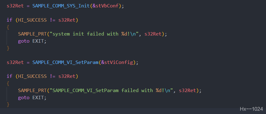
Hisilicon 3559 sample parsing: Vio
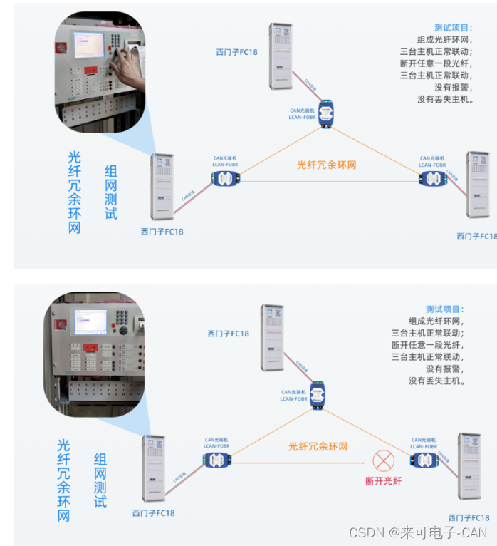
三台西门子消防主机FC18配套CAN光端机进行光纤冗余环网组网测试

Importer des données dans MATLAB
將數據導入到MATLAB

Can transparent cloud gateway caniot and candtu record can messages and send and receive can data remotely

年后求职找B端产品经理?差点把自己坑惨了......

力扣 272. 最接近的二叉搜索树值 II 递归

Machine learning notes linear regression of time series

网络模型——OSI模型与TCP/IP模型
随机推荐
Can bus working condition and signal quality "physical examination"
电子学:第012课——实验 11:光和声
50. pow (x, n) - fast power
Do you know why the PCB produces tin beads? 2021-09-30
三台西门子消防主机FC18配套CAN光端机进行光纤冗余环网组网测试
洛谷P3313 [SDOI2014]旅行(树链+边权转点权)
ffmpeg+SDL2实现音频播放
Sword finger offer II 027 Palindrome linked list
1464. maximum product of two elements in an array
环网冗余式CAN/光纤转换器的CAN光端机在消防火灾联网报警系统中的应用
时钟刻度盘的绘制
洛谷P2486 [SDOI2011]染色(树链+线段树 + 树上区间合并 )
Runtime - Methods member variable, cache member variable
[deep learning lightweight backbone] 2022 edgevits CVPR
SCM Project Training
2021ICPC网络赛第一场
判断用户是否是第一次进入某个页面
协议和服务的区别?
NPM install reports an error: gyp err! configure error
c#ColorDialog更改文本颜色和FontDialog更改文本字体的使用示例