当前位置:网站首页>Can bus protocol Foundation
Can bus protocol Foundation
2022-06-10 16:47:00 【Please trust me】
List of articles
Reference material
What is? CAN Bus
CAN(Controller Area NetWork) It was Germany in the early 1980s Bosch The company aims to solve many control units in modern vehicles (ECU) A kind of software developed for data exchange between Multi host local area network serial communication protocol .( It can be understood that for the use of fewer cables , Cost saving technology )
about CAN, In fact, it can be simply understood as a conference call , When one person speaks, others listen ( radio broadcast ), When more than one person speaks at the same time, they will decide who speaks first and who speaks later according to certain rules ( arbitration ), It's like you and the leader talking at the same time in a meeting , You must be very tactful to let the leader speak first .
CAN Bus structure diagram

Baidu collects it casually , Don't you mind?
CAN Advantages of bus
With the development of communication technology , Nowadays, there are various communication methods and protocols , however CAN Communication is still one of the most secure, reliable and widely used technologies in vehicle network .
In the past , The automobile usually adopts the conventional point-to-point communication mode to connect the electronic control unit and electronic device , But with the increasing number of electronic devices , The number of conductors also increases , use CAN Bus network structure , Information can be shared , Reduce cabling , The goal of reducing costs and improving overall reliability .
In general CAN The bus has the following advantages :
- Relatively high data transmission speed , Accessible 1Mbit/s.(CAN-FD and CAN-XL Each can achieve 2Mbit/s and 10Mbit/s)
- Use differential data lines , Strong anti-interference ability ;
- Multi master communication mode , Greatly reduce the cost of single point communication harness ;
- Self diagnostic function with error listening , Reliable communication and high reliability .
CAN Bus Principle and working mechanism
Hardware foundation
CAN There are two hardware schemes for bus nodes
- MCU controller + Independent CAN controller +CAN Transceiver .( Independent CAN The controller is as follows: NXP Semiconductor SJA1000 etc. ) Use independent CAN The controller program has good reusability and portability , But it takes up the main chip I/O resources .
- Integrate CAN Controller MCU+CAN Transceiver .( Integrate CAN The microcontroller of the controller is as follows NXP Semiconductor P87C591 etc. ) The program reusability of this scheme is poor , It has a strong pertinence , But it can make the circuit simpler .
Here's the picture , complete CAN The interface circuit includes Receive and send CAN The message CNA controller , Convert digital signals and CAN The signal CAN Transceiver , A filter that eliminates noise and provides appropriate impedance CAN Gao He CAN Low terminal circuit .

Communication mechanism
The transmission of electrical signals is realized by distinguishing the high and low voltage at the physical level ,CAN Communication is no exception .CAN The bus is twisted pair Differential voltage transmission , Two signal lines are called CAN high (CAN_H) and CAN low (CAN_L).
Both lines are static 2.5V about , At this time, the state representation logic is 1, Also known as Recessive . When the voltage values of the two lines are different , Usually CAN_H=3.5V and CAN_L = 1.5V, At this point, the state is represented as logic 0, Also known as dominance . namely : Differential signal voltage CAN_diff = 0V, To express logic “1”, Recessive ; Differential signal voltage CAN_diff = 2V, To express logic “0” , For dominance ;
notes : In the actual development, the voltage of both lines will fluctuate around the standard value , This is also the advantage of differential transmission , Reduce the interference caused by error and noise .
Logic for explicit level “0” Express , The hidden level uses logic “1” Express , There may be a little friend who has questions , How do you feel the opposite , Is it wrong ?
In fact, this is because CAN The bus adopts " Line and " Rules for conflict arbitration ( Solve the problem of who will speak ), namely When more than one CAN When signals are sent at the same time , Some hair 1 Some hair 0, And as long as there is 0, The current bus is 0 (1 & 0 = 0), It looks like 1 By 0 covers . On the other hand , In terms of potential , The high potential is 0, When 1 and 0 When sending at the same time , The bus is at high potential , It just shows up 0, So the 0 Specified as explicit .
CAN Message frame format
Communicating with each other ECU Want to send and receive messages from each other , Need to use same CAN Message format , It's like two people with different mother tongues have to speak the same language to talk , Otherwise, it's just the same story . At present, there are mainly CAN2.0A and CAN2.0B Two technical specifications .
CAN2.0A Specifies the 11 Standard frame format for bit identifiers ,CAN2.0B On this basis, a new method with 29 Extended frame format of bit identifier .
CAN Message frames can be divided into four types according to different purposes : Data frame , Remote frame , Wrong frame , Overload frame .
Data frame
For data transfer 
Frame start : Marks the beginning of a data frame , Only by one dominance A composition , Can only be sent when the bus is idle . Arbitration court : In standard frame , The Arbitration Court consists of 11 Bit identifier and RTR A composition ; In the extended frame , The Arbitration Court consists of 29 Bit identifier 、SRR position 、IDE Bit and RTR A composition .
ID( identifier ) Is used to identify a message , Indicate message meaning and priority .
RTR( Remote transfer request bit ), Data frame RTR position Must be dominant level (RTR=0), Remote frame RTR Bit must be hidden level (RTR = 1).
IDE( Identifier extension ) The standard frame belongs to the control field , It belongs to the arbitration field in the extended frame . In standard frame IDE Is the dominant level (IDE=0), In the extended frame IDE Is the recessive level (IDE=1)
SRR( Remote substitute request bit ) Always recessive level in extended frame (SRR=1)
Control field : from 6 A composition . In standard frame , The control field includes IDE( This is the dominant level 0), Keep a r( This is the dominant level 0) as well as Occupy 4 individual bit Data length code DLC. In the extended frame , The control field does not IDE position , But two reserved bits r0 and r1, At this time, it is also the dominant level 0.
Data field : contain CAN Data sent by data frame ,0~8byte. The format is shown in the following figure 
This is a common tool for automotive electronics engineers CANode Inner message layout A screenshot of , About CANode The use of and simulation programming pay attention to the blog at the back of this column . Here, let's take a look at this picture . The first column is from 0 To 7 Each represents a frame of message 8 individual byte From low to high ,0 That is the first. 0 individual byte,7 That is the first. 7 individual byte, Here we should pay attention to the first byte Write it down as 0.
First line from 7 To 0 respectively byte[0] The signals are arranged from high to low ,7 That is the first. 7 individual bit,0 That is the first. 0 individual bit, Also note that the lowest order is bit[0]. That's why ,CAN Like all signals, messages are transmitted by 0 and 1 Combined information , After a certain CAN The agreement can be translated into the result we want .
CRC site : Include CRC Sequence sum CRC Delimiter DEL,CRC The verification is made for the safety and reliability of both sides of the communication “ Code ”, Only the sender calculates based on the transmitted information CRC Value and the value calculated by the receiver according to the received information CRC The value is right , To judge that the communication was successful , Otherwise you will report an error .
The reply (ACK) site : Include 2 position , Reply gap (ACK) And response delimiter (DEL). In the message sent by the sending node ACK And DEL All are hidden levels 1, The receiving node will use the dominant level after receiving correctly 0 Cover hidden level , To indicate correct reception . The conclusion is that , Receive... Correctly ACK=0,DEL=1; Not properly received ACK=DEL=1.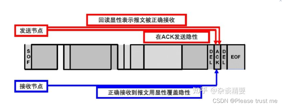
End of the frame :7 A continuous recessive bit , Indicates the end of the data frame . The node is detecting 11 The bus is considered idle after consecutive recessive bits .
Remote frame
Request to send data frames with the same identifier to other nodes , The remote frame has no data field , And RTR Bit is hidden level
To put it another way , Remote frames are like a command , If node A Need nodes B Send him data , that A You need to send a remote frame to B,B When received, the data frame will be sent to A.
Wrong frame
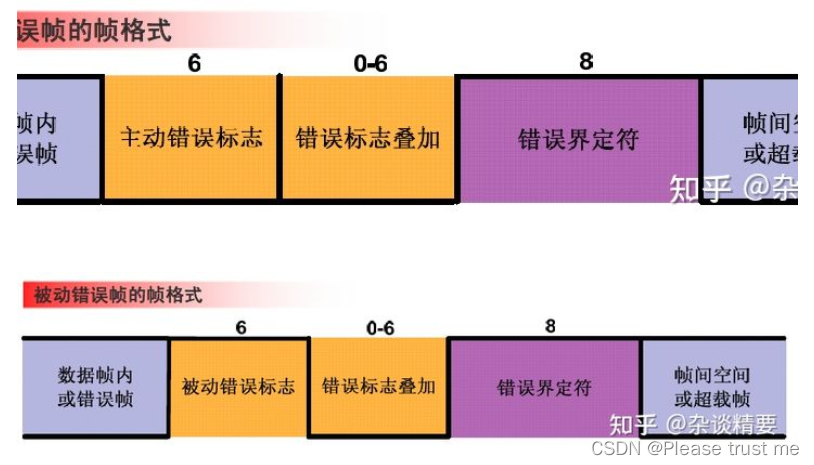
When a node detects that one or more of the CAN The error defined by the standard , An error frame will be generated . Error frame consists of error flag and error delimiter .
Error flags are divided into active error flags and passive error flags :
- The active error flag consists of 6 A continuous
dominanceA composition ; - The passive error flag consists of 6 A continuous
RecessiveA composition , Unless overridden by the dominant bits of other nodes ; - The error delimiter is defined by 8 Consists of consecutive recessive bits .
When to send an error frame with an active error flag ? When to send an error frame with a passive error flag ? First, let's talk about the error status of the node
Three error states of the node
Active error status : The node is in an active error state and can communicate normally 、 Node in active error state ( It may be a receiving node or a sending node ) When detecting errors , Send active error flag .
Passive error status : The node is in a passive error state and can communicate normally , Node in passive error state ( It may be a receiving node or a sending node ) When detecting errors , Issue a passive error flag .
Bus off state : The node is in the bus off state and cannot send or receive messages , Can only wait for , Only when certain conditions are met can it enter the active error state again and send and receive messages normally .
One CAN When a node is in an active error state , When in a passive error state ? according to CAN Provisions of the agreement ,CAN There are two counters in the node : Send error counter TEC And receive error counter REC,CAN The node determines the status according to the size of the two counter values
- 0<REC<=127 And 0<TEC< =127 when , The node is in
Active error status. In this state , When a node detects an error, it will send an error frame with a doomed error flag , Because the active error flag is six consecutive dominant bits , So at this time, the active error flag will cover other bit signals on the bus , such CAN The messages previously transmitted on the bus are destroyed by these six dominant bits . This is equivalent to that the node that finds the error actively stands up and tells other nodes on the bus , There is something wrong with the signal just now , You don't want to receive processing , Just throw it away . - If a node sends error frames more times , So much so that REC>127 or TEC>127, Then the node is in a passive error state . In this state , When a node detects an error, it sends an error frame with a passive error flag , Because the passive error flag is six consecutive hidden bits , Therefore, the messages transmitted on the bus at this time will not be affected by the passive error frame , Other nodes receive and send normally .
- A node that is already in a passive error , Still send passive error frames multiple times , Eventually making TEC>255, In this way, the bus is turned off .
In this state , The node cannot send and receive messages, Offline from bus . Only when... Is detected 128 Time 11 When there are consecutive recessive bits ,TEC and REC Will be reset 0, The node returns to the active error state .
CAN Bus error classification 
CAN How the node counter counts 
Overload frame
Overloaded frames are used for previous and subsequent data frames ( Or remote frame ) Provide an additional delay between , The overload sign is marked by 6 A dominant position consists of , The overload delimiter is defined by 8 Consists of consecutive recessive bits .
CAN Bus non-destructive arbitration
stay CAN Each message sent on the bus is unique 11 Bit or 29 Digit number ID, When nodes send messages at the same time CAN The bus will press “ Line and ” The mechanism is right ID Every one of the judges , When a node sends 0 The status of the bus is 0. therefore ID The smaller the value, the higher the priority , This is why the more important message on the whole vehicle ID The smaller the value. .
As shown in the following figure 1、2、3 Send messages at the same time , Compare... In turn ID Every one of them , node 3 Of ID Minimum value , In the end CAN Control of the bus 
CAN Bus bit filling mechanism
CAN The bus adopts various anti-interference measures to reduce errors in the transmission of message frames , Bit filling is one of the most important techniques .CAN The jump edge of the bus specified signal is the synchronization signal , So as long as the signal changes , The node clock will be synchronized . But if the same signal is sent continuously , No jump occurs , Then the sending and receiving nodes may not be synchronized , Thus, the signal is abnormal . So when it detects 5 Two consecutive identical bit signals , The actual sending will automatically insert a complement to send , And then send the original signal
SOF Previous bus free area , No need to synchronize , No bit padding is required .CRC The following bit fields are all in fixed format , Bit fill operation is not allowed .
CAN Bus bit timing and synchronization
Bit timing means CNA The duration of one data bit on the bus , It is mainly used for CAN Communication baud rate setting of each node on the bus , The communication baud rate on the same bus must be the same .
Normal bit time = 1/ Baud rate .( such as 1Mbit/s Baud rate , The sending time of one bit is 1 subtle )
Bit time can be divided into the following four segments :
- Synchronization segment : Used to synchronize different nodes on the bus , A jump edge is required in this section ;
- Communication section : Used to compensate for CAN Physical latency on the network ;
- Phase buffer section 1 and 2: Used to compensate phase error , It can be lengthened or shortened by resynchronization .

CAN The communication data stream does not contain clock information ,CAN The synchronization defined in the bus specification ensures that the message can be correctly decoded regardless of the phase error accumulated between nodes .
CAN The synchronization methods of include Hard sync and Resynchronization Two kinds of :
- Only one synchronization mode is allowed in a bit time , Either hard sync or resynchronize ;
- Any falling edge from recessive to dominant can be used for synchronization ;
- Hard synchronization occurs at the end of the message SOF position ( Frame start ), All receiving nodes adjust the synchronization segment of their current bit , Put it in the sending position SOF In place ;
- Resynchronization occurs in a message SOF Other than bits , Resynchronization occurs when the falling edge falls outside the synchronization segment ;
- stay SOF Within the time period of sending to the arbitration site , If multiple nodes send messages at the same time , Then these sending nodes do not resynchronize the jump edge .
Hard sync Sent on SOF position , All receiving nodes adjust the synchronization segment of their current bit , The adjustment width is unlimited .
Sending node Node_A Sending SOF When a ,SOF The falling edge of the bit is synchronized (SS) paragraph , This is the time NodeB Find your current position SS Segment and sending node SOF Bit synchronization SS Segment out of sync , So receive Node_B Force your current position SS Paragraph pull to and SOF Bit SS Segment synchronization .
Resynchronization Occurs in a message SOF Other venues beyond the level , When the receiving node Node_b The falling edge of the current bit falls on the sending node Node_A Resynchronization occurs outside the synchronization segment of the current bit .
Late , Collect early , It will cause phase buffer segment 1 extend . Sending node Node_A The current bit of SS When the segment is generated , Receiving node Node_B The current bit of SS Duan has been produced before him , At this time, the receiving node Node_B It will be extended for a period of time Node_A The sampling points of .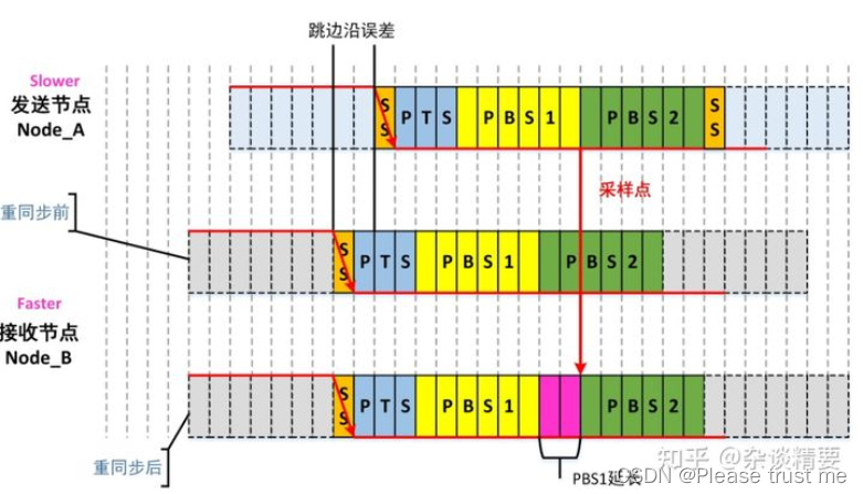
Hair early , Late collection , Will cause phase buffering 2 To shorten the . Sending node Node_A The current bit of SS The segment generation time is earlier than the receiving node Node_B The current bit of SS Segment generation time , At this time, the receiving node Node_B To shorten the phase buffer 2, To ensure that the two sampling points are synchronized .
thus CAN The basic principle of is over , Interested students can go to B Watch the tutorial on the website ( Including experiments )
Portal
边栏推荐
- Query convert quickview is a grayed out solution (turn)_ SAP LIUMENG
- Why__ Inline usually needs static
- 卷起來,突破35歲焦慮,動畫演示CPU記錄函數調用過程,進互聯大廠如此簡單
- [today in history] June 10: Apple II came out; Microsoft acquires gecad; The scientific and technological pioneer who invented the word "software engineering" was born
- Apache atlas quick start
- [untitled]
- Why do I need a thread pool? What is pooling technology?
- Report on development status and investment planning recommendations of global and Chinese fuel filler pipe markets (2022-2028)
- Weilai quarterly report diagram: the revenue was 9.9 billion yuan, a year-on-year increase of 24%, and the operating loss was nearly 2.2 billion yuan
- Actual combat of software testing e-commerce project (actual combat video station B has been released)
猜你喜欢
Technology sharing | quick intercom, global intercom

Why do I need a thread pool? What is pooling technology?

袋鼠云数栈基于CBO在Spark SQL优化上的探索

Devops software architecture evolution

Analysis of different dimensions of enterprise reviewers: enterprise growth of Hunan Great Wall Science and Technology Information Co., Ltd

Investment prospect and development strategy planning of China's waste power generation equipment industry 2022-2028 Edition

Add Anaconda's bin directory to path
Ar smart contact lens market prospect trends and development planning proposal report 2022-2028

迪赛智慧数——文字(文本墙):80后儿童时期风靡的25种玩具

Software College of Shandong University Project Training - Innovation Training - network security range experimental platform (XVII)
随机推荐
Basic settings of pycharm [detailed explanation with pictures and words]
Download and install pycharm integrated development environment [picture]
简单实现文件上传
Basic use cases for jedis
6. Mgr status monitoring | Mgr in simple terms
Pictographic dynamic graphic ideographic data
Can deleted wechat friends be recovered? How to retrieve wechat friends after they are accidentally deleted
From web2 to Web3, ideology also needs to change
Common sense: the number of neurons in the brain of mice is about 70million and that of humans is about 86billion
rmq 2333
LocalDate与Date相互转换
数字图像处理:灰度化
Why do I need a thread pool? What is pooling technology?
Li Ling: in six years, how did I go from open source Xiaobai to Apache top project PMC
Analysis of different dimensions of enterprise reviewers: enterprise growth of Hunan Great Wall Science and Technology Information Co., Ltd
Basic use of pycharm
Android 13 re upgrade for intent filters security
Software College of Shandong University Project Training - Innovation Training - network security range experimental platform (16)
Link multiple alamofire requests - chain multiple alamofire requests
Desai wisdom number - words (text wall): 25 kinds of popular toys for the post-80s children