当前位置:网站首页>Teach you how to use Hal library to get started -- become a lighting master
Teach you how to use Hal library to get started -- become a lighting master
2022-07-01 00:12:00 【Please trust me】
List of articles
Preface
Thank you very much for your teaching and answers , It is highly recommended that students go to baiwen.com to learn embedded knowledge
Official website of baiwen.com
Basic knowledge of
The clock

- HSI: Internal high speed clock
- LSI: Internal low speed clock
- HSE: External high-speed clock
- LSE: External low speed clock
Because the internal clock is easily affected by the chip temperature , So the accuracy is not very good . Therefore, the external clock is generally used .
GPIO I / O mode of

Push pull output :
The push-pull structure consists of two MOS The tubes are connected in a complementary and symmetrical manner , At any time, one of the triodes is always on , The other triode is off . Such as ① Shown , The interior consists of a P-MOS Tube and a N-MOS Tube composition , Two MOS The grid of the tube ( Gate, G) Receive
Left “ Output control ” , Drain electrode ( Drain, D) Connected to external output , P-MOS The source of the tube ( Source, S) Receive VDD( 3.3V),N-MOS The source of the tube is connected to Vss( 0V).
MOS The tube is used as a switch ,“ Output control ” To two MOS Apply a certain voltage to the tube grid , P-MOS Conduction between the source and drain of the tube ,VDD after P-MOS Tubular S->G->D Output , N-MOS The tube is in a high resistance state ( The resistance is very high , Approximate open circuit ), The overall external is high level ;“ Output control ” Cancel to two MOS Apply voltage to the tube grid , P-MOS Tube source and grid cut-off ,P-MOS The tube is in a high resistance state , N-MOS The source and drain of the tube are connected , The overall external is low level .
Push pull mode , Give Way “ Output control ” Change into VDD/Vss Output , Increase the output current , The driving ability of the output pin is improved , Improve
The load capacity of the circuit and the action speed of the switch .Open drain output
In open drain mode ,“ Output control ” Will not control P-MOS tube , “ Output control ” Only to N-MOS Apply a certain voltage to the tube grid , Two
MOS All tubes are in the cut-off state , The two drains are suspended , It's called open drain .“ Output control ” Cancel the applied voltage of the grid , PMOS The tube is still in the high resistance state , N-MOS The pipe is open , The overall external is low level .
Multiplexing push pull output / Reuse open drain output
GPIO In addition to being a general-purpose input / The output pin uses an external pin , It can also be used as an on-chip peripheral ( USART、 I2C、 SPI etc. ) Dedicated pin , That is, one pin can be used for many purposes , But one pin can only use one of the multiplexing functions at the same time .
When the pin is set to the multiplexing function , The multiplexed push-pull output mode or multiplexed open drain output mode can be selected , Set to multiplex open drain output mode
when , It needs to be connected with pull resistance .Pull up input
Such as ② Shown , VDD Through the switch 、 Pull up resistance , Connect external I/O Pin . When the switch is closed , external I/O When there is no input signal , The default input is high .
The typical application of this mode is the external key , When no key is pressed , MCU The pin of is the determined high level , When the key is pressed , The pin level is pulled to low level .Drop down input
Such as ② Shown , Vss Through the switch 、 Pull down resistance , Connect external I/O Pin . When the switch is closed , external I/O When there is no input signal , The default input is low .Floating input
Such as ② Shown , Two up / The pull-down resistance switches are disconnected , Neither pull-up nor pull-down , I/O The pins are connected directly TTL Schottky trigger , here I/O The pin is floating , The reading level is uncertain , What level is the external signal , MCU The pin inputs what level . MCU
Reset after power on , The default is floating input mode .Analog input
Such as ② Shown , Two up / The pull-down resistance switches are disconnected , meanwhile TTL The Schottky trigger switch is also off , The pin signal is directly connected to the analog input , Realize the acquisition of external signals .
CubeMX To configure


First step , Set the clock 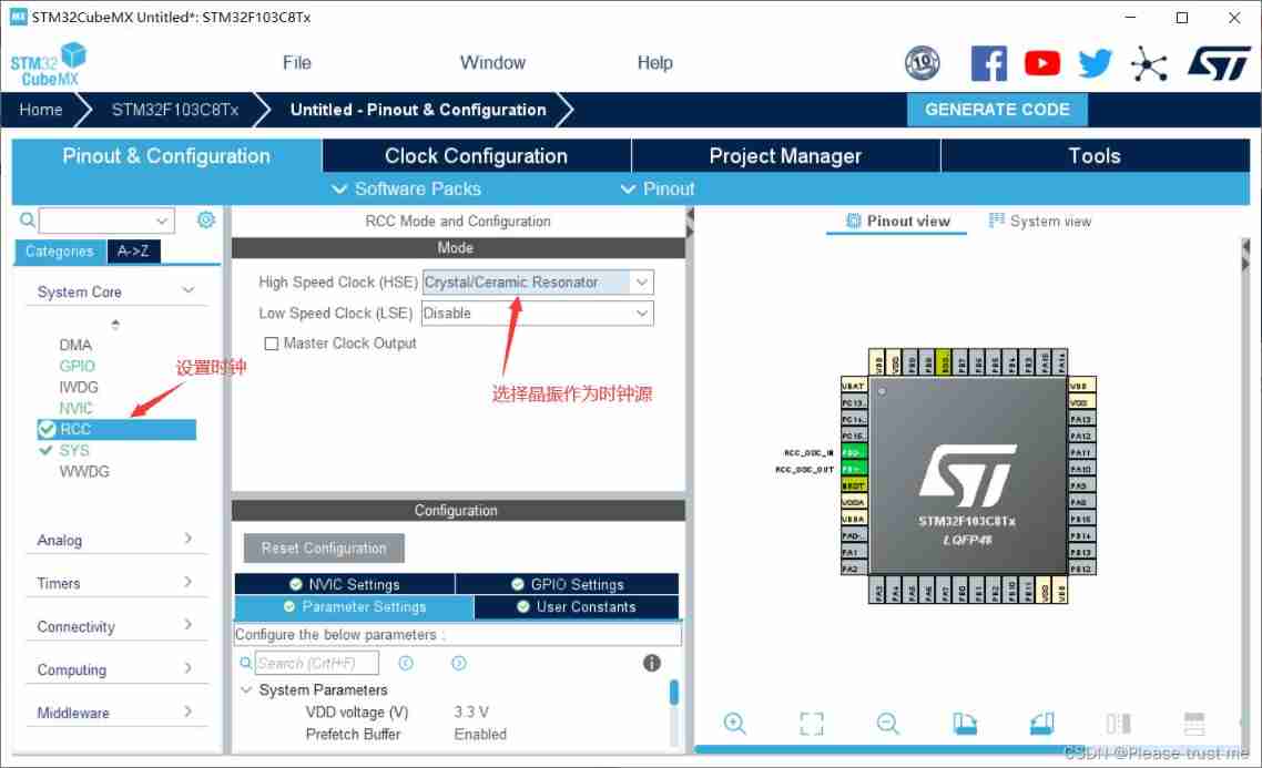

The second step , To configure GPIO Pin
First, check the schematic diagram , find LED And the buttons 


Keil Programming
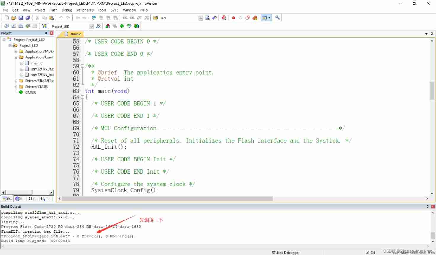

The main program 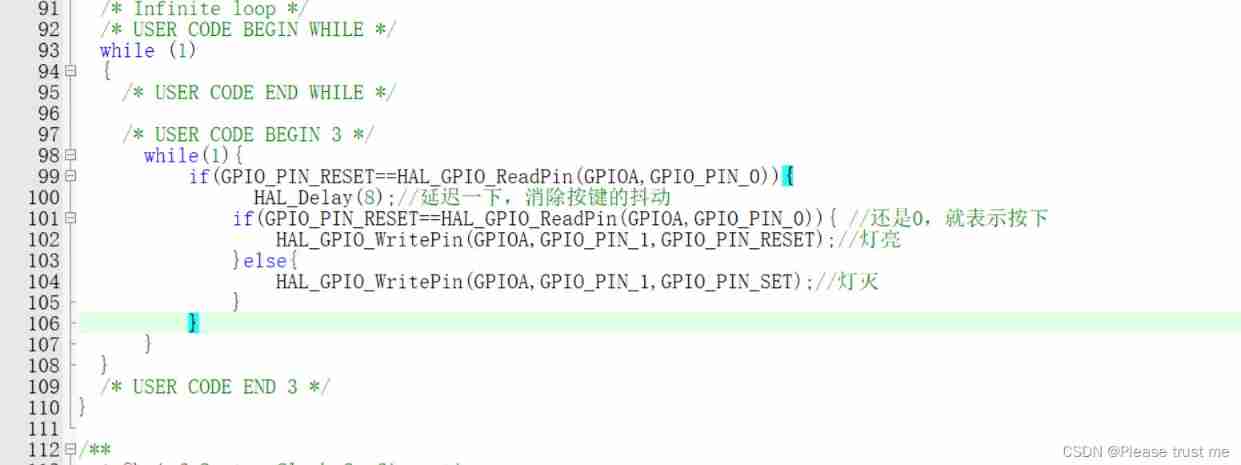
main.c
/* USER CODE BEGIN Header */
/** ****************************************************************************** * @file : main.c * @brief : Main program body ****************************************************************************** * @attention * * Copyright (c) 2022 STMicroelectronics. * All rights reserved. * * This software is licensed under terms that can be found in the LICENSE file * in the root directory of this software component. * If no LICENSE file comes with this software, it is provided AS-IS. * ****************************************************************************** */
/* USER CODE END Header */
/* Includes ------------------------------------------------------------------*/
#include "main.h"

/* Private includes ----------------------------------------------------------*/
/* USER CODE BEGIN Includes */

/* USER CODE END Includes */

/* Private typedef -----------------------------------------------------------*/
/* USER CODE BEGIN PTD */

/* USER CODE END PTD */

/* Private define ------------------------------------------------------------*/
/* USER CODE BEGIN PD */
/* USER CODE END PD */

/* Private macro -------------------------------------------------------------*/
/* USER CODE BEGIN PM */

/* USER CODE END PM */

/* Private variables ---------------------------------------------------------*/

/* USER CODE BEGIN PV */

/* USER CODE END PV */

/* Private function prototypes -----------------------------------------------*/
void SystemClock_Config(void);
static void MX_GPIO_Init(void);
/* USER CODE BEGIN PFP */

/* USER CODE END PFP */

/* Private user code ---------------------------------------------------------*/
/* USER CODE BEGIN 0 */

/* USER CODE END 0 */

/** * @brief The application entry point. * @retval int */
int main(void)
{

  /* USER CODE BEGIN 1 */

  /* USER CODE END 1 */

  /* MCU Configuration--------------------------------------------------------*/

  /* Reset of all peripherals, Initializes the Flash interface and the Systick. */
  HAL_Init();

  /* USER CODE BEGIN Init */

  /* USER CODE END Init */

  /* Configure the system clock */
  SystemClock_Config();// System clock configuration

  /* USER CODE BEGIN SysInit */

  /* USER CODE END SysInit */

  /* Initialize all configured peripherals */
  MX_GPIO_Init(); //GPIO initialization
  /* USER CODE BEGIN 2 */

  /* USER CODE END 2 */

  /* Infinite loop */
  /* USER CODE BEGIN WHILE */
  while (1)
  {

    /* USER CODE END WHILE */

    /* USER CODE BEGIN 3 */
      while(1){

          if(GPIO_PIN_RESET==HAL_GPIO_ReadPin(GPIOA,GPIO_PIN_0)){

                HAL_Delay(8);// Delay , Eliminate key jitter
              if(GPIO_PIN_RESET==HAL_GPIO_ReadPin(GPIOA,GPIO_PIN_0)){
     // still 0, It means pressing
                  HAL_GPIO_WritePin(GPIOA,GPIO_PIN_1,GPIO_PIN_RESET);// Light on
              }else{

                  HAL_GPIO_WritePin(GPIOA,GPIO_PIN_1,GPIO_PIN_SET);// The light goes out
              }
          }
      }
  }
  /* USER CODE END 3 */
}

/** * @brief System Clock Configuration * @retval None */
void SystemClock_Config(void)
{

  RCC_OscInitTypeDef RCC_OscInitStruct = {
    0};
  RCC_ClkInitTypeDef RCC_ClkInitStruct = {
    0};

  /** Initializes the RCC Oscillators according to the specified parameters * in the RCC_OscInitTypeDef structure. */
  RCC_OscInitStruct.OscillatorType = RCC_OSCILLATORTYPE_HSE;
  RCC_OscInitStruct.HSEState = RCC_HSE_ON;
  RCC_OscInitStruct.HSEPredivValue = RCC_HSE_PREDIV_DIV1;
  RCC_OscInitStruct.HSIState = RCC_HSI_ON;
  RCC_OscInitStruct.PLL.PLLState = RCC_PLL_ON;
  RCC_OscInitStruct.PLL.PLLSource = RCC_PLLSOURCE_HSE;
  RCC_OscInitStruct.PLL.PLLMUL = RCC_PLL_MUL9;
  if (HAL_RCC_OscConfig(&RCC_OscInitStruct) != HAL_OK)
  {

    Error_Handler();
  }
  /** Initializes the CPU, AHB and APB buses clocks */
  RCC_ClkInitStruct.ClockType = RCC_CLOCKTYPE_HCLK|RCC_CLOCKTYPE_SYSCLK
                              |RCC_CLOCKTYPE_PCLK1|RCC_CLOCKTYPE_PCLK2;
  RCC_ClkInitStruct.SYSCLKSource = RCC_SYSCLKSOURCE_PLLCLK;
  RCC_ClkInitStruct.AHBCLKDivider = RCC_SYSCLK_DIV1;
  RCC_ClkInitStruct.APB1CLKDivider = RCC_HCLK_DIV2;
  RCC_ClkInitStruct.APB2CLKDivider = RCC_HCLK_DIV1;

  if (HAL_RCC_ClockConfig(&RCC_ClkInitStruct, FLASH_LATENCY_2) != HAL_OK)
  {

    Error_Handler();
  }
}

/** * @brief GPIO Initialization Function * @param None * @retval None */
static void MX_GPIO_Init(void)
{

  GPIO_InitTypeDef GPIO_InitStruct = {
    0};

  /* GPIO Ports Clock Enable */
  __HAL_RCC_GPIOD_CLK_ENABLE();
  __HAL_RCC_GPIOA_CLK_ENABLE();

  /*Configure GPIO pin Output Level */
  HAL_GPIO_WritePin(GPIOA, GPIO_PIN_1, GPIO_PIN_RESET);

  /*Configure GPIO pin : PA0 */
  GPIO_InitStruct.Pin = GPIO_PIN_0;
  GPIO_InitStruct.Mode = GPIO_MODE_INPUT;
  GPIO_InitStruct.Pull = GPIO_NOPULL;
  HAL_GPIO_Init(GPIOA, &GPIO_InitStruct);

  /*Configure GPIO pin : PA1 */
  GPIO_InitStruct.Pin = GPIO_PIN_1;
  GPIO_InitStruct.Mode = GPIO_MODE_OUTPUT_PP;  // Push pull output
  GPIO_InitStruct.Pull = GPIO_PULLUP;   // Pull up
  GPIO_InitStruct.Speed = GPIO_SPEED_FREQ_LOW;
  HAL_GPIO_Init(GPIOA, &GPIO_InitStruct);

}

/* USER CODE BEGIN 4 */

/* USER CODE END 4 */

/** * @brief This function is executed in case of error occurrence. * @retval None */
void Error_Handler(void)
{

  /* USER CODE BEGIN Error_Handler_Debug */
  /* User can add his own implementation to report the HAL error return state */
  __disable_irq();
  while (1)
  {

  }
  /* USER CODE END Error_Handler_Debug */
}

#ifdef USE_FULL_ASSERT
/** * @brief Reports the name of the source file and the source line number * where the assert_param error has occurred. * @param file: pointer to the source file name * @param line: assert_param error line source number * @retval None */
void assert_failed(uint8_t *file, uint32_t line)
{

  /* USER CODE BEGIN 6 */
  /* User can add his own implementation to report the file name and line number, ex: printf("Wrong parameters value: file %s on line %d\r\n", file, line) */
  /* USER CODE END 6 */
}
#endif /* USE_FULL_ASSERT */
Experimental phenomena
No problem 
边栏推荐
- MySQL index test
- Development of wireless U-shaped ultrasonic electric toothbrush
- Red hat will apply container load server on project atomic
- Repetition is the mother of skill
- Asynchronous transition scenario - generator
- Is it safe to open a stock account of Huatai Securities online?
- Examples of topological sequences
- Five minutes to understand the exploratory test
- [designmode] factory pattern
- Dataloader source code_ DataLoader
猜你喜欢

2022-2028 global plant peptone industry research and trend analysis report
2022-2028 global ICT test probe industry research and trend analysis report

Ditto set global paste only text shortcuts

Which is better, server rental or hosting services in the United States?

Implementation of OSD on Hisilicon platform (1)
2022-2028 global herbal diet tea industry research and trend analysis report

206页上海BIM技术应用与发展报告2021

MaxPool2d详解--在数组和图像中的应用

shell 同时执行多任务下载视频

When is it appropriate to replace a virtual machine with a virtual machine?
随机推荐
Sm2246en+ SanDisk 15131
Explain kubernetes backup and recovery tools velero | learn more about carina series phase III
File reading and writing for rust file system processing - rust Practice Guide
Reason why wechat payment wxpaypubhelper V3 callback XML is empty
[NLP] [textcnn] text classification
Fund customer service
HP notebook disable touchpad after mouse is inserted
Matlab saves triangulation results as STL files
2022-2028 global plant peptone industry research and trend analysis report
Manage edge browser settings (ie mode, homepage binding, etc.) through group policy in the enterprise
Redis - sentinel mode
The girlfriend said: if you want to understand the three MySQL logs, I will let you heiheihei!
Summer Challenge [FFH] harmonyos mobile phone remote control Dayu development board camera
76 page comprehensive solution 2022 for smart Logistics Park (download attached)
The programmer's girlfriend gave me a fatigue driving test
2022-06-30: what does the following golang code output? A:0; B:2; C: Running error. package main import “fmt“ func main()
Rust book materials - yazhijia Library
Implementation of OSD on Hisilicon platform (1)
Vmware16 installing win11 virtual machine (the most complete step + stepping on the pit)
基金銷售行為規範及信息管理