当前位置:网站首页>PCB miscellaneous mail
PCB miscellaneous mail
2022-06-26 07:45:00 【Wonderful drifting of coal】
A brief description of the signal and signal integrity :
In any type of PCB When the design , Obviously , You will send from the input to the desired region of interest via copper wire . The signal you will send can be a digital signal , It can also be an analog signal .
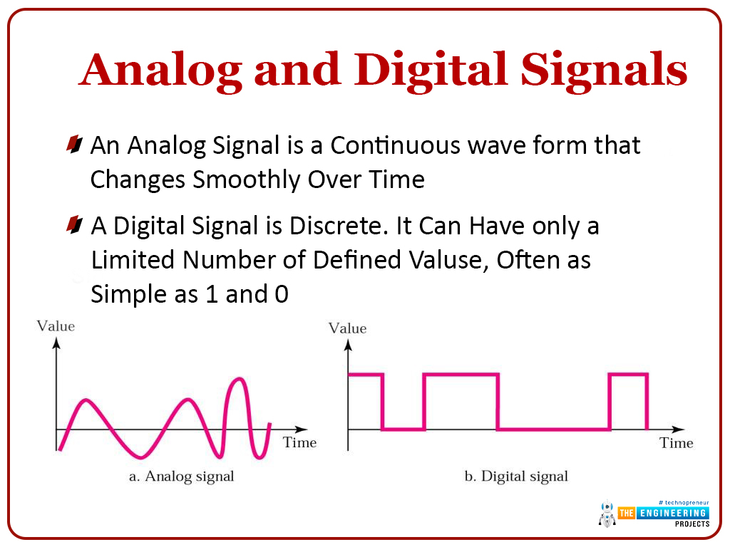
digital signal
- Also called a square signal , It is output , You will always encounter any digital signals that exist on this planet .
- Unlike analog signals with random numbers everywhere , The digital signal has a well-organized result system , By high and low or 1 and 0 Express , Some even call them close and open .
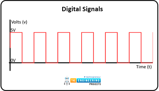
- Let's look at the following digital signals .
analog signal
- This type of signal has random output points , Consists of negative and positive values .
- Different from digital signals with open and close points , Analog signals have random results , These results are defined by frequency and signal strength .
- The following are the outputs that should be expected when using analog signals .
![[ Failed to transfer the external chain picture , The origin station may have anti-theft chain mechanism , It is suggested to save the pictures and upload them directly (img-Io9FAzLU-1644927186531)(https://www.theengineeringprojects.com/wp-content/uploads/2021/12/7-21.jpg)]](https://www.theengineeringprojects.com/wp-content/uploads/2021/12/7-21.jpg)
The main problem with these signals is that they are susceptible to interference , This is where we introduce signal integrity , Because whenever the signal is affected by the environment , There will be some problems .
Let's take a look at the following example .
Suppose you have a circuit that is sending a signal from PCB In plate 1 Point is transmitted to the 2 spot . spot 1 Can be classified as a transmitter , spot 2 Can be classified as a receiver . When the signal goes from point 1 Move to point 2 when , The signal may be affected by different factors , for example ;
- The signal rings ; When the current or voltage is shifted unnecessarily , That's what happens , This will result in the flow of additional current in the trace , So as to delay the arrival of the signal .
![[ Failed to transfer the external chain picture , The origin station may have anti-theft chain mechanism , It is suggested to save the pictures and upload them directly (img-4P9Cbxea-1644927186532)(https://www.theengineeringprojects.com/wp-content/uploads/2021/12/8-21.jpg)]](https://www.theengineeringprojects.com/wp-content/uploads/2021/12/8-21.jpg)
- Signal reflection ; This is when your signal is in coper Flow in the track , But when the whole signal cannot reach the destination , Because some of these signals are reflected back to the origin .
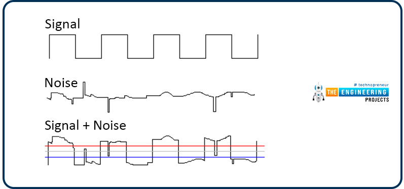
- Signal noise ; When there is random signal fluctuation in the circuit board , That's what happens , This in turn will affect the signal close to it . Fluctuation may eventually damage the signal data transmitted in the circuit board .
- Signal timing ; Sometimes , When you send a signal over copper wire , They will not reach that goal in time , So it can match the clock signal . When that happens , The signal may be interpreted as zero , And in reality , It's for 1. This is called signal timing .
- Signal crosstalk ; When you place two copper wires too close to each other , That's what happens , Because the wiring carries different signals . Electromagnetic radiation emitted from one signal may affect another signal , So as to affect the data flowing in it .
![[ Failed to transfer the external chain picture , The origin station may have anti-theft chain mechanism , It is suggested to save the pictures and upload them directly (img-B3PiAVkR-1644927186533)(https://www.theengineeringprojects.com/wp-content/uploads/2021/12/10-16.jpg)]](https://www.theengineeringprojects.com/wp-content/uploads/2021/12/10-16.jpg)
Design rules and challenges of high-speed design .
Just like any engineering work , When we deal with high speed PCB When the design , Some rules must be observed . Let's delve into some of these challenges ; Let's look at some of these challenges .
Adjust the trace length
ad locum , If you are using a high-speed interface , The length of the trace must be signal adjusted , In order to synchronize the signal propagation . If you miss the synchronization , Then your interface will fail at a very high frequency , It doesn't even work . therefore , In high-speed design , Tuning is a very important aspect .
- In any high-speed design , There should be two types of interference , Parallel and serial interfaces .
- The parallel interface will only involve the length of the routing tuning , For the serial interface , The signals are combined into several differential pairs .
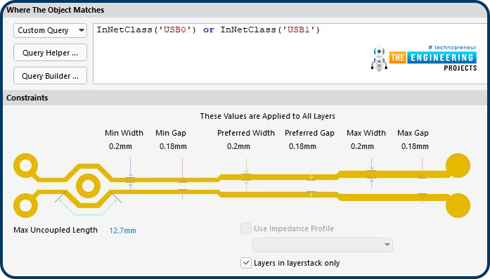
- Tuned differential pairs
- The following is the tuning length of the track ;
[[ Failed to transfer the external chain picture , The origin station may have anti-theft chain mechanism , It is suggested to save the pictures and upload them directly (img-gXIeZ85a-1644927186534)(https://www.theengineeringprojects.com/wp-content/uploads/2021/12/13-14.jpg)]](
边栏推荐
- Detailed materials of applying for residence permit in non local Beijing
- [recommend an entity class conversion tool mapstruct, which is powerful and easy to use]
- You can command Siri without making a sound! The Chinese team of Cornell University developed the silent language recognition necklace. Chinese and English are OK
- What is Wi Fi 6 (802.11ax)? Why is Wi Fi 6 important?
- Sanic based services use celery to complete dynamic modification timing tasks
- Error: the specified LINQ expression contains a reference to a query associated with a different context
- Young man, do you know the original appearance of kotlin association process?
- Mxnet implementation of network in Nin network
- Jemter 压力测试 -可视化工具-【使用篇】
- Jemter stress test - visualization tool support - [installation]
猜你喜欢
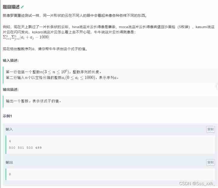
Niuniu looks at the cloud (greedy, hash, push formula) - the first session of Niuke winter vacation training camp

My colleague asked a question I never thought about. Why did kubernetes' superfluous' launch the static pod concept?

Attention mechanism yyds, AI editor finally bid farewell to P and destroyed the whole picture

How to define a digital factory and what is the relationship with smart factory and industry 4.0

我想造SQL数据(存储结构)
Tsinghua Yaoban chendanqi won Sloan award! He is a classmate with last year's winner Ma Tengyu. His doctoral thesis is one of the hottest in the past decade

Web technology sharing | webrtc recording video stream

What is the difference between bone conduction earphones and ordinary earphones? Advantages of bone conduction earphones

Jemter 壓力測試 -基礎請求-【教學篇】

Jemter 压力测试 -可视化工具支持-【安装篇】
随机推荐
QT之一个UI里边多界面切换
CMDA 3634 image processing
数据中心灾难恢复的重要参考指标:RTO和RPO
Google Earth Engine(GEE) 01-中输入提示快捷键Ctrl+space无法使用的问题
SQL
Nine hours, nine people and nine doors (01 backpack deformation) - Niuke
Minor problems in importing D
What are the characteristics of digital factory in construction industry
Redis series - five common data types day1-3
[NLP] vector retrieval model landing: Bottleneck and solution!
Systemctl PHP configuration file
How MySQL implements the RC transaction isolation level
Jemter stress test - Basic request - [teaching]
[UVM practice] Chapter 3: UVM Fundamentals (3) field automation mechanism
Liangshui Xianmu shows his personal awareness as a unity3d worker
Open a file at line with'filename:line'syntax - open a file at line with'filename:line' syntax
Children play games (greed, prefix and) - Niuke winter vacation training camp
Informatics Orsay all in one 1354: bracket matching test
php array_ Merge details
JMeter stress test web agent local interface test [teaching]