当前位置:网站首页>[sequential logic circuit] - counter
[sequential logic circuit] - counter
2022-07-24 16:43:00 【Li Yuchen】


Welcome to learn digital circuit —— Sequential logic circuit .
Here we will talk about binary counters 、 Decimal counter and integrated counter 74LS161, I hope that through our study, you will better understand the mystery of digital circuits .
Catalog
(1) Asynchronous binary addition counter
(2) Synchronous binary addition counter
(1)74LS161 Pin arrangement and graphic symbols of the chip
One 、 Counter
A digital circuit that can accumulate the number of input pulses is called a counter , Counter is a unit logic circuit widely used in digital circuits , Except directly used as technology 、 frequency division 、 Out of time , It is also often used in digital instruments 、 Program control 、 In the fields of computers and so on .
There are many kinds of counters ,
① The carry system by count is different , It can be divided into binary 、 Decimal and N Binary counter, etc ;
② Press the increment of the value in the counter 、 Reduce the situation , It can be divided into addition counters 、 Subtraction counter 、 Reversible counter ;
③ According to the different state transition time of each trigger in the counter , It can be divided into synchronous counter and asynchronous counter .
1. Binary counter
Definition :
Under the action of counting pulse , The digital circuit that counts the state transition of each trigger according to the binary coding law is called Binary counter .
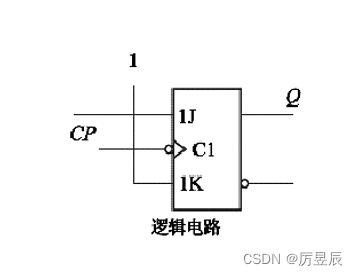
The core device that constitutes the counter circuit has the counting function JK trigger . Can be JK The trigger is connected to the counting state , As shown in the figure :
(1) Asynchronous binary addition counter
As shown in the figure, the circuit uses three JK Trigger connected asynchronism 3 Bit binary addition counter .

Of triggers in the figure  Terminated together as a direct reset input signal to the counter ; The counting pulse is added to the lowest trigger Of FF0 End , Other triggers CP Receive low trigger in turn Q End control . When each trigger receives a negative jump pulse signal, the state will flip .
The waveform is shown in the figure :

working process :
Before counting , At the reset end First input a negative pulse , send =000, This process is called clearing , After clearing , Should make
=1, To count normally .
When the first counting pulse CP After action , The falling edge of the pulse causes the trigger FF0 Of  from 0 State to 1 state , The other two triggers have no CP The function of the falling edge , Still hold 0 state , So when the first CP After action , The counter status is
 =001.
When the second counting pulse CP When it works , trigger FF0 Flip , from 1 State to 0 state , The falling edge of is added to FF1 Clock input of , send  from 0 State to 1 state , The rising edge changes to the trigger FF2 Invalid ,
 The state remains the same , So when the second CP After action , The counter status is
 =010.
And so on , Be the seventh CP The counter status is 111, Be the eighth CP After the action, the counter returns to 000 state , Complete a counting cycle .
(2) Synchronous binary addition counter
As shown in the figure, synchronization 3 Bit binary addition counter :

Trigger of all levels CP End to end , Controlled by the same clock pulse , Obviously, the flip-flop state of each trigger is synchronized with the clock , Therefore calls Synchronous counter .
2. Decimal counter
The structure of binary counter is simple , Easy to calculate . But on many occasions , Using decimal counter is more in line with people's habits . The so-called decimal counter is a digital circuit that counts the state conversion of each trigger under the action of counting pulse according to the coding law of decimal number .
The method of expressing decimal numbers with binary numbers is called Two — Decimal code ( namely BCD code ). Decimal numbers have 0~9 common 10 Number , At least use 4 Bit binary number . and 4 Bit binary numbers have Sixteen States , Express 1 Decimal numbers only need ten states , So we need to remove six of them . It is often used in decimal counters 8421BCD Code encoding method for counting .
8421 The code is shown in table :

(1) Circuit composition
The asynchronous decimal addition counter circuit is composed of 4 Bit binary counter and a gate circuit for clearing the counter , The main difference with binary addition counter is that it skips binary digits 1010~1111 Of 6 Status .

(2) working process
Counter input 0~9 When counting pulses , Working process and 4 Bit binary asynchronous counters are exactly the same , After the ninth counting pulse  =1001.
When the tenth counting pulse arrives , The counter status is =1010, here  , NAND gate input all 1, Output is 0, Reset each trigger , namely =0000, At the same time, the NAND gate output becomes 1, The counter starts working again . So as to achieve 8421BCD Code decimal The function of adding and counting .
3. Integrated counter
The integrated counter integrates the trigger and the closed circuit on a chip , Easy to use and expand . There are many types of medium scale integrated synchronous counters , common 4 Bit decimal synchronous counter has 74LS160、74LS162、74LS196、CC40192 etc. ;4 Bit binary synchronous counter has 74LS161、74LS163、74LS169、74LS191 etc. .
(1)74LS161 Pin arrangement and graphic symbols of the chip
74LS161 The pin arrangement and graphic symbols of the chip are shown in the figure :

① Asynchronous reset
When asynchronously set 0 Control terminal  =0 when , Regardless of the state of other inputs , With or without clock pulses , The counter output will be set directly to zero , It is called asynchronous zeroing .
② Sync preset number
When =1 when , Synchronous setting control terminal  =0, And in CP When the rising edge acts , The parallel input data is placed at the output of the counter , send =
 . Because this operation is related to CP Sync , So it is also called synchronous preset .
The truth table is shown in the table :

③ keep
at that time ==1、 when , Output remain unchanged . Then if
  =0、
=0、 =1, Then carry output signal CO remain unchanged ; if =1、=0, Carry output signal CO Low level .
④ Count
When ====1 when ,CP When the rising edge is valid , Realize the function of adding and counting .
【 Sequential logic circuit 】 It's over , In the next issue, we will open a new chapter ——【 Generation and transformation of pulse waveform 】
边栏推荐
- 15. ARM embedded system: how to debug single board with PC
- More than 40 Qualcomm chips have been exposed to security vulnerabilities, affecting billions of mobile phones!
- JUC source code learning note 3 - AQS waiting queue and cyclicbarrier, BlockingQueue
- Qt设计机器人仿真控制器——按键控制机器人关节转动
- 双指针滑动窗口法解析及LeetCode相关题解
- 小端格式和大端格式(Little-Endian&Big-Endian)
- 【零基础】充分理解WebGL(八)
- 15、ARM嵌入式系统:如何用PC调试单板
- Creation and inheritance of JS class
- Chapter 2 using API Mgmnt service
猜你喜欢


随机推荐
Chapter 2 using API Mgmnt service
[Nanjing Agricultural University] information sharing of postgraduate entrance examination and re examination
QT keyboard event (I) -- detect key input
Template method mode
Wentai technology's revenue in the first quarter soared by 184.6% year-on-year, and its net profit soared by 256.21%!
More than 40 Qualcomm chips have been exposed to security vulnerabilities, affecting billions of mobile phones!
"Heaven and the world, self-respect" -- single case mode
百度推广“删除重提”是什么意思?
Unity camera free movement control
MySQL basic commands
Complete guide on how to prevent cross site scripting (XSS) attacks
剑指 Offer 22. 链表中倒数第k个节点
Multithreading (basic)
Codeforces round 690 (Div. 3) B. last year's substring conventional solution
双指针滑动窗口法解析及LeetCode相关题解
Cross server, insert, search
Jupyter uses tips
GEO satellite data download
Codeworks round 693 (Div. 3) C. long jumps problem solution
804. Unique Morse code word