当前位置:网站首页>Some explanations of Tim timer of embedded interface and STM32 template library function of NVIC
Some explanations of Tim timer of embedded interface and STM32 template library function of NVIC
2022-06-23 23:27:00 【Icy Hunter】
List of articles
Preface
The following will explain STM32 Timer in TIM Some basic operations . This is also one of the key contents of the exam , I'm not impressed when I just read it by myself , Writing a blog will force you to understand more .
Basic method of timing
1. Software delay :CPU To perform a “ empty ” Program implementation delay
advantage : No need to add additional hardware devices , Easy to implement
shortcoming : Occupy CPU Time , Accuracy is interrupted and CPU The main frequency clock affects
2. Hardware delay circuit : Using additional digital circuits ( Such as 555 Monostable chip ) Generate a specific delay .
advantage : Not occupy CPU Time
shortcoming : Changing the delay time requires adjusting the circuit parameters ( resistance 、 Capacitance value ), Poor versatility and flexibility , Time accuracy is affected by circuit parameters , Poor stability
3. Programmable timer ( Counter ):
With a dedicated chip ( Such as Intel8253) or MCU Timer interface device integrated in ( Such as STM32 Medium TIM1~8 ) For timing .
advantage : After the timer is initialized, it is independent of CPU Work , Not occupy CPU Time , For any length of time , Flexible and high precision .
shortcoming : Increase hardware costs
STM32 The clock of
51 The single chip microcomputer adopts a clock module composed of quartz crystal and oscillation circuit , To provide clock pulses for the system . This kind of clock circuit has simple structure , The frequency of the output clock depends on the resonant frequency of the quartz crystal , And only a single frequency clock output . Affected by processing technology, etc , High frequency quartz car costs a lot , The required frequency is 72MHz Etc , PLL technology is commonly used to raise the low-frequency clock signal to a higher frequency .
STM32 Intraslice Division ARM Cortx - M3 kernel , There are also many peripherals with different uses , There are peripherals that require high-speed clocks , There are also peripherals that require a low-speed clock , Therefore, the frequency divider is also required to reduce the clock frequency to a suitable frequency for peripheral use .
STM Timer for TIM
Structure of general timer

As you can see from the diagram STM32 The universal timer of is divided into time base unit 、 The output comparison unit and the input capture unit are three major parts .
Time base unit

Simply speaking, the time base unit can realize the counting function , Take counting up as an example , After timer initialization , A clock selected as a counter clock source CS_PSK After the prescaler divides the frequency, it is applied to the counter as a counting pulse , The value of the counter increases with CK_CNT Start from 0 Increasing , When the count reaches the automatic reload value (ARR Value ) after , Generate counter up overflow update event , And start a new round of counting .
Example explanation
problem : Use timer interface TIM3, Realization 1s timing , utilize TIM3 Timer interrupt , After interrupting the service program, let LED0~1 Flash once .
I'll talk about STM32 The core code for in the template library
TIM_TimeBaseInit
Used to initialize the corresponding timer peripheral 
TIM_TimeBaseInitTypeDef

The general values and explanations of each parameter are as follows :


TIM_Cmd
Used to enable TIMx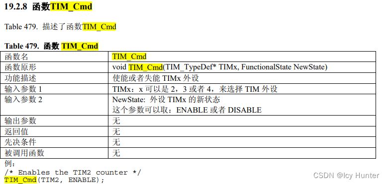
TIM _ITConfig
To enable or enable TIM The interrupt .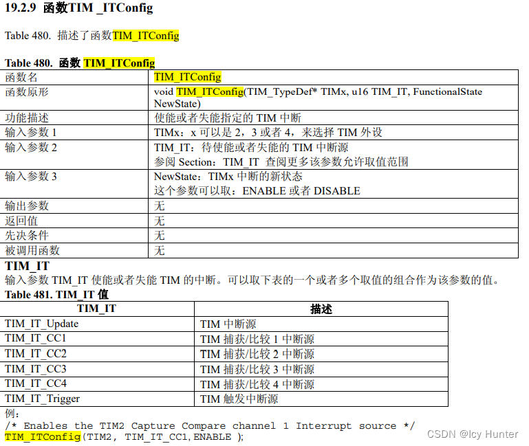
Core code
TIM_TimeBaseInitTypeDef TIM_TimeBaseStructure;
// Can make TIM3 The clock of
RCC_APB1PeriphClockCmd(RCC_APB1Periph_TIM3, ENABLE);
// The counter counts 10000 An update event occurs every time ( Because from 0 Start with -1)
TIM_TimeBaseStructure.TIM_Period = 10000-1;
// Divider settings 7200( Because from 0 Start with -1), Then the system clock will change to... After passing through the frequency divider 10KHz
// Then count through the counter 10K / 10K = 1Hz, That's right. 1s once
TIM_TimeBaseStructure.TIM_Prescaler = 7200-1;
// Set up TIM3 Control register CR1 Of CKD[2:0] = 00, send tDTS = tCK_INT
TIM_TimeBaseStructure.TIM_ClockDivision = 0x0;
// Upcount mode
TIM_TimeBaseStructure.TIM_CounterMode = TIM_CounterMode_Up;
// initialization TIM3
TIM_TimeBaseInit(TIM3, &TIM_TimeBaseStructure);
// allow TIM3 Update interrupt
TIM_ITConfig(TIM3, TIM_IT_Update, ENABLE);
// Set up TIM3 The controller CR1 Of CEN position , Turn on timer TIM3
TIM_Cmd(TIM3, ENABLE);
Due to the use of TIM Interrupt implementation , Then interruptions cannot be separated from NVIC, Therefore, you also need to configure NVIC And for the interrupt service program , I won't list them one by one here .
Output comparison unit

The output comparison function consists of a capture / Compare register CCR And counter CNT And the corresponding output part .
In the process of running , If CNT==CCR1 Then do the following :
Set the channel output value : Output comparison mode OC1M[2:0] ( Capture / Compare mode register TIMx_CCMR1 in ) Determine the intermediate signal OC1REF A high value is valid ,OC1REF And output active pole
Sexual selection bit CC1P( Capture / Compare enable register TIMx_CCER) decision OC1 Output value .
Example explanation
utilize TIM3 The output comparison function of , produce 10Hz The square wave , Used to control LED0 flashing .
analysis : Give Way TIM3 The basic timer works on 0.5s Timing status (20Hz ), recycling TIM3_CH2 Channel output comparison function , stay “ If it is equal, the mold will be reversed ” Under the formula , Each interval 0.5s, A flip occurs , produce 10Hz Square wave output of .
You need to call TIM Corresponding output comparison mode , Therefore, you also need to use the corresponding interface driver function . But the library I have may be a little old , This code doesn't seem to be right , I won't go into details about the functions and parameters . Just go straight to the core code
TIM_TimeBaseInitTypeDef TIM_TimeBaseStructure;
// Can make TIM3 The clock of
RCC_APB1PeriphClockCmd(RCC_APB1Periph_TIM3, ENABLE);
// The counter counts 500 An update event occurs every time ( Because from 0 Start with -1)
TIM_TimeBaseStructure.TIM_Period = 500-1;
// Divider settings 7200( Because from 0 Start with -1), Then the system clock will change to... After passing through the frequency divider 10KHz
// Then count through the counter 10K / 500 = 20Hz
TIM_TimeBaseStructure.TIM_Prescaler = 7200-1;
// Set up TIM3 Control register CR1 Of CKD[2:0] = 00, send tDTS = tCK_INT
TIM_TimeBaseStructure.TIM_ClockDivision = 0x0;
// Upcount mode
TIM_TimeBaseStructure.TIM_CounterMode = TIM_CounterMode_Up;
// initialization TIM3
TIM_TimeBaseInit(TIM3, &TIM_TimeBaseStructure);

TIM_OCInitTypeDef TIM_OCInitStructure;
// initialization TIM3_CH2 Output flip mode
TIM_OCInitStructure.TIM_OCMode = TIM_OCMode_Toggle;
// Compare output enable
TIM_OCInitStructure.TIM_OutputState = TIM_OutputState_Enable;
// Output polarity ,TIM High output polarity
TIM_OCInitStructure.TIM_OCPolarity = TIM_OCPolarity_High;
// Set the compare output register TIM3_CCR2 Value , Each count reaches 200 The secondary signal is reversed once , Timer output 20Hz, Then the square wave is 10Hz,(0-499 Fine , Because the counter range is 0-499)
TIM_OCInitStructure.TIM_Pulse = 200;
// initialization TIM3_OC2
TIM_OC2Init(TIM3, &TIM_OCInitStructure);
// Can make TIM3 stay CCR2 Preload register on
TIM_OC2PreloadConfig(TIM3, TIM_OCPreload_Enable);
// Can make TIM3
TIM_Cmd(TIM3, ENABLE);
Input capture unit
Input capture refers to the detection of the level change of the input signal of the pin , When a level change is found , Save the value of the counter into the input capture register , At the same time, set the input capture status flag bit ; If interrupt is allowed , to CPU Make an interrupt request , Then it can measure the time interval between events and respond to real-time events .
purpose : Radar speed measurement 、 Ultrasonic ranging 、 Measurement of engine speed and vehicle speed, etc .

The input capture function consists of a capture signal input section ( Digital filtering 、 Edge detection and prescaler ), Capture / Compare register TIMx_CCRx And the counter CNT form .
Input filter pair TI1 The input signal is sampled and filtered to obtain the signal TI1F, After the edge detector with polarity selection, the effective edge signal is obtained TI1FP1, Then the input acquisition signal is obtained IC1, This signal is obtained by frequency division IC1PS. When an effective IC1PS After coming , The capture event is triggered , The current value of the counter is latched to the capture / Compare register TIMx_CCR1 in , Simultaneous passage 1 Capture / Comparison marks CC1IF(TIMx_SR register ) Be placed 1.
Example explanation
utilize TIM2 Input capture function , Measure any PWM Frequency and duty cycle of the signal .
The core code is as follows :
	TIM_TimeBaseInitTypeDef TIM_TimeBaseStructure;
	TIM_ICInitTypeDef TIM_ICInitStructure;
	NVIC_InitTypeDef NVIC_InitStructure;

	// Define the clock frequency and set ARR To the maximum
	u32 CK_INT_FREQ = 72000000;
	// Define the internal clock source CK_INT The frequency is 72MHz
	u32 CK_CNT_FREQ = 1000 * 1000;
	// Set the prescaler ratio PSC Value
	u16 PrescalerValue = (u16)(CK_INT_FREQ/CK_CNT_FREQ-1);
	// ARR Count the initial value 65535, measuring range :PWM cycle <65536 * 1us = 0.06536s
	//PWM frequency  > 16.258Hz
	u16 ARRValue = 65535;
	// Can make the clock
	RCC_APB1PeriphClockCmd(RCC_APB1Periph_TIM2, ENABLE);

    // Set timer reset mode and select reset trigger signal
	TIM_SelectSlaveMode(TIM2, TIM_SlaveMode_Reset);
	// take TIM2 Reset slave mode (SMS=100), Every time TRIG Jumping up the edge causes TIM2_CNT Reset .
	// choice TI1FP As a trigger signal TRIG
	TIM_SelectInputTrigger(TIM2, TIM_TS_TI1FP1);

	// To configure TIM2 Timer
	TIM_TimeBaseStructure.TIM_Period = ARRValue;
	TIM_TimeBaseStructure.TIM_Prescaler = PrescalerValue;
	TIM_TimeBaseStructure.TIM_ClockDivision = 0;
	// Upcount mode
	TIM_TimeBaseStructure.TIM_CounterMode = TIM_CounterMode_Up;
	TIM_TimeBaseInit(TIM2, &TIM_TimeBaseStructure);

	// Set up TIM2 Capture channel for IC1
	TIM_ICInitStructure.TIM_Channel=TIM_Channel_1;
	//TIM2_TI1 The input signal is not filtered
	TIM_ICInitStructure.TIM_ICFilter=0x0;
	//IC1 choice TI1 Edge polarity signal TI1FP1(CC1S=01)
	TIM_ICInitStructure.TIM_ICSelection=TIM_ICSelection_DirectTI;
	// The rising edge triggers capture
	TIM_ICInitStructure.TIM_ICPolarity = TIM_ICPolarity_Rising;
	//IC1 Signals are not allocated IC1PS
	TIM_ICInitStructure.TIM_ICPolarity = TIM_ICPSC_DIV1;
	// initialization TIM2 Of IC1
	TIM_PWMIConfig(TIM2, &TIM_ICInitStructure);
	// allow IC1 Capture interrupt
	TIM_ITConfig(TIM2, TIM_IT_CC1, ENABLE);
	// Can make IC1 Input capture interrupt
	TIM_ClearITPendingBit(TIM2, TIM_IT_CC1);
	 Turn on TIM2
	TIM_Cmd(TIM2, ENABLE);

	// To configure NVIC
	NVIC_PriorityGroupConfig(NVIC_PriorityGroup_2);
	NVIC_InitStructure.NVIC_IRQChannel = TIM2_IRQn;
	NVIC_InitStructure.NVIC_IRQChannelPreemptionPriority = 0;
	NVIC_InitStructure.NVIC_IRQChannelSubPriority = 3;
	NVIC_InitStructure.NVIC_IRQChannelCmd = ENABLE;
	NVIC_Init(&NVIC_InitStructure);


//-------------------------------------------------------------------
//NVIC Interrupt service routine
	float PWMDutyResult=0;
	float PWMFreqResult=0;
	u16 IC1Value=0;
	u16 IC2Value=0;
	void TIM2_IRQHandler(void)   // Interrupt service routine
{

	IC1Value=TIM_GetCapture1(TIM2);
	IC2Value=TIM_GetCapture2(TIM2);
	if(IC1Value != 0 && IC2Value != 0)
	{

	PWMDutyResult = (float)(IC2Value+1) * 100 / (IC1Value + 1);
	PWMFreqResult = (float)(1000000 / (IC1Value + 1));

	// Clear the interrupt flag bit
	TIM_ClearITPendingBit(TIM2, TIM_IT_CC1);
	}
}
边栏推荐
- Operation and maintenance failure experience sharing
- The principle of async and await
- Urgent! Tencent cloud container security supports the detection of Apache log4j2 vulnerabilities for the first time. It is in free trial
- Aicon2021 | AI technology helps content security and promotes the healthy development of Internet Environment
- Isolement des transactions MySQL
- 2022 cloud consulting technology series storage & CDN special sharing meeting
- 抖音支付十万级 TPS 流量发券实践
- 迪赛智慧数——柱状图(基本柱状图):2022年父亲节过节的方式
- PHPMailer 发送邮件 PHP
- sql server常用sql
猜你喜欢

C# Winform 自定义进度条ProgressBar

Ambire Guide: the arbitrum odyssey begins! Week 1 - Cross Chain Bridge

The Sandbox 归属周来啦!

Cs5213 HDMI to VGA with audio signal output scheme

远程办公之:如何成为时间管理大师?| 社区征文
Detailed quaternion
CS5213 HDMI转VGA带音频信号输出方案
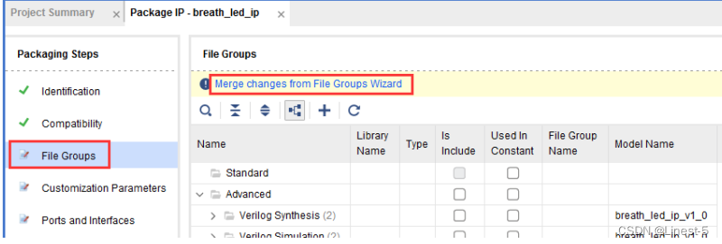
【Xilinx AX7103 MicroBalze学习笔记6】MicroBlaze 自定义 IP 核封装实验
C# 读取内存条占用大小,硬盘占用大小

《阿里云天池大赛赛题解析》——O2O优惠卷预测
随机推荐
Notes to nodejs (III)
图论(树的直径)
《阿里云天池大赛赛题解析》——O2O优惠卷预测
什么是免疫组织化学实验? 免疫组织化学实验
What are the processes, levels, stages and key points of requirements analysis in software development
Bilibili × Blue bridge cloud course | online programming practice competition is new!
Micro build low code tutorial - Application creation
巨头下场“摆摊”,大排档陷入“苦战”
What is the development prospect of face recognition technology?
百万消息量IM系统技术要点分享
MySQL数据库配置信息查看与修改方法详解
How to set ulimit value for SYSTEMd service in easycvr?
Postman可以集成到CI,CD流水线中做自动化接口测试吗?
Practice of issuing vouchers for Tiktok payment of 100000 TPS traffic
Kotlin 集合List 、Set、Map操作汇总
AIX系统月维护查什么(一)
Cause analysis and Countermeasures for FANUC robot srvo-050 collision detection alarm (available for personal test)
Detailed process of deploying redis cluster and micro service project in docker
WebService客户端请求失败 can not create a secure xmlinputfactory
Installation and use of qingscan scanner