当前位置:网站首页>QT compile the Internet of things management platform 36- communication protocol
QT compile the Internet of things management platform 36- communication protocol
2022-06-22 10:06:00 【feiyangqingyun】
One 、 Preface
By default, the system adopts modbus agreement , Support serial port and network rtu Pattern , Other communication protocols will be introduced later, such as mqtt etc. , You can select the communication protocol from the port management drop-down menu .
1.1 Communication process
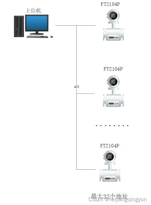
- The overall structure is : The controller is attached to the communication port , There are multiple detector nodes under one controller , Equivalent to main equipment 、 Sub equipment .
- Because you need to traverse the polling , Therefore, the controller address on a communication port cannot be duplicated .
- Different communication ports , The controller address can be repeated , Therefore, if there are many controllers, they can be divided into different communication ports .
- Multiple detectors can be attached to one controller , The controller is also constantly polling the detector data and recording , Wait for the polling command of the upper computer program , Package and send the detector data back together .
- This software only communicates with the controller , Not communicating with the detector , The controller is responsible for communicating with the detector . Why is it designed like this ? Because this architecture is the most common , The number of equipment that can be connected is also the largest .
- The system defaults to the standard modbus Protocol to communicate ,modbus Is a standard communication framework protocol , Support serial port, network and other communication methods , Whether to communicate through serial port or network depends on the equipment manufacturer .
- modbus Is a communication protocol framework , As for the data meaning of each byte of the specific data bit , Each manufacturer is different , All customized by the manufacturer , commonly 2 Bytes represent a data .
- Ports can be serial ports and network ports , Different communication resolution protocols can be selected when adding ports .
1.2 Interpretation of the agreement
- Host sending refers to the software sending data to the device , Take the initiative to send .
- The slave response is the response data made by the equipment according to the received data , Passive reply .
- A send command corresponds to a reply command .
- Register address 2 byte , High in front, low in back .
- Read length 2 byte , High in front, low in back .
- Data bits 2 byte , High in front, low in back .
- CRC check 2 byte , Low in front, high in back .
- The function code has 03( Read only register )、04( Read, read, and write registers )、06( Write read write register ).
- The function code sent by the master is the same as the function code replied by the slave .
1.2.1 Host send
| Address | Function code | Register address | Number of registers | CRC check |
|---|---|---|---|---|
| 01 | 03 | 00 00 | 00 04 | 44 09 |
1.2.2 Slave response
| Address | Function code | length | Data bits 1 | Data bits 2 | Data bits 3 | Data bits 4 | CRC check |
|---|---|---|---|---|---|---|---|
| 01 | 03 | 08 | 00 00 | 00 00 | 00 00 | 00 00 | 95 D7 |
1.2.3 Read length
| Model of equipment | length | explain |
|---|---|---|
| FC1003-1 | 01 | |
| FC1003-8 | 08 | |
| FC1003-16 | 08 08 | Equivalent to two FC1003-8, Different device addresses . |
| FC1003 Display panel | 40 | The length shall be adjusted according to the number of connected equipment , The maximum is 64 individual . |
| FC1003 floor | 04 | |
| FT2104P | 01 | |
| SAMS-4128 | 08 |
1.2.4 Data examples
Note
- The following example data CRC The check bits are used uniformly XX XX Express , Too lazy to calculate .
- The addresses filled in this system are from 1 Start counting , So fill in 1 Says from the 0 Start reading .
- If the register address 01 01 , be 0101=257, This system shall be filled with 258, fill 258 the truth is that -1=257=0101 send out .
- Number of registers , It can also be said to be the number of node devices .
- A data bit or a node's data is 2 Bytes of data .
- Read length 1 Will return 1 Data bits in total 2 Bytes of data .
- Read length 2 Will return 2 Data bits in total 4 Bytes of data .
- Read length 3 Will return 3 Data bits in total 6 Bytes of data .
Example data 1
- send out :01 03 00 00 00 02 XX XX
- explain : From register address 0(00 00 = 0) Start , Read 2 A register .
- return :01 03 04 42 C7 FF EA XX XX
- explain : return 4 Bytes of data 42 C7 FF EA , Corresponding register address 0、1 The data of .
- To configure : Controller address 1, Detector address 1、2.
Example data 2
- send out :01 03 01 01 00 01 XX XX
- explain : From register address 257(01 01 = 257) Start , Read 1 A register .
- return :01 03 02 02 EF XX XX
- explain : return 2 Bytes of data 02 EF , Corresponding register address 257 The data of .
- To configure : Controller address 1, Detector address 258.
Example data 3
- send out :AA 03 AA BB 00 04 XX XX
- explain : From register address 43707(AA BB = 43707) Start , Read 4 A register .
- return :AA 03 08 55 AC 23 65 84 77 C3 3F XX XX
- explain : return 8 Bytes of data 55 AC 23 65 84 77 C3 3F , Corresponding register address 43707、43708、43709、43710 The data of .
- To configure : Controller address 170(AA = 170), Detector address 43708、43709、43710、43711.
Two 、 Functional characteristics
2.1 Software modules
- Equipment monitoring module , Including data monitoring ( Show... In tabular form )、 Device panel ( Display in panel form )、 Map monitoring ( Display in map form )、 Curve monitoring ( Show in curve form ).
- Data query module , Including alarm records 、 Operation record 、 Operation record .
- System setup module , Including basic settings 、 Port Management 、 Controller management 、 Detector Management 、 Alarm linkage 、 Type setting, etc .
- Other setting modules , Including user management 、 Map Management 、 Position adjustment 、 Configuration design 、 Equipment commissioning, etc .
2.2 Basic function
- Device data acquisition , Support serial port 、 The Internet , Serial port can set serial port number 、 Baud rate , The network can be set IP Address 、 Communication port .
- Each port supports acquisition cycle time , Default 1 One device per second .
- Support to set communication timeout times , Default 3 Time .
- Support maximum reconnection time , For rereading offline devices .
- Controller information , Can add controller name , Select the controller address 、 Controller model , Set the number of detectors under the controller .
- Detector information , Can add tag number 、 Detector model 、 Gas type 、 Gas symbol 、 High reported value 、 Under reported value 、 Buffer value 、 Zero value 、 Is it enabled? 、 Alarm sound 、 Background map 、 Storage cycle 、 The number of decimal places for numerical conversion 、 Alarm delay time 、 Type of alarm (HH,LL,HL) etc. .
- Type management configurable controller model 、 Detector model 、 Gas type 、 Gas symbols, etc .
- Map supports importing and deleting , The positions of all detectors on the map can be dragged and saved freely .
- Port information 、 Controller information 、 Detector information 、 Type information 、 User information, etc , Both support import 、 export 、 Export to excel、 Print .
- Operation record 、 Alarm records 、 Operation record , Both support multi condition combined query , For example, time period 、 controller 、 Detector, etc , All records support export to excel/pdf And print .
- Operation record 、 Alarm records 、 All operation records can delete data within a specified time range .
- The system can select the maximum number of records saved in the corresponding table , Automatically clean up early data , Leave enough space for important data .
- Alarm SMS forwarding , Support multiple receiving mobile numbers , The sending interval can be set , Like instant delivery or 6 Send all alarm messages once an hour , The message is too long , Automatically split multiple messages .
- Alarm mail forwarding , Support multiple receiving mailboxes , The sending interval can be set , Like instant delivery or 6 Send all alarm messages once an hour , Support attachment sending .
- Set the Chinese title of the software 、 English title 、logo route 、 All rights reserved .
- The switch is set for startup and operation 、 Alarm sound 、 automatic logon 、 Remember the password, etc .
- Alarm sound can be set to play times , Interface style provides 18 Set skin file selection .
- User management , Including user permission configuration , Different users can have different module permissions .
- User login and user logout , Can remember password and auto login , More than three error prompts and close the program .
- Four monitoring modes , Equipment panel monitoring 、 Map monitoring 、 Form data monitoring 、 Curve data monitoring , Free to switch , The collected data is displayed in real time in all four modes , Alarm flashing, etc .
- Alarm relay linkage , A tag number can link multiple modules and relay numbers across serial ports , Support many to many .
2.3 Special function
- Communication protocol supports modbus_com、modbus_tcp_rtu, Later expansion mqtt Such agreement .
- The data source is in addition to the real hardware device collection , Optional database acquisition , In this way, users can arrange other programmers, such as java The programmer puts the data collected by the front end into the database , The system can collect data directly from the database . Database collection mode can be used as a general system , More suitable for multi person and multi system cooperation .
- Smart skip timeout device , Speed up the acquisition of online devices , Especially useful when there are a large number of devices .
- For smart skip timeout devices , Automatically collect once at the set reconnection time , In order to detect whether the equipment is online again .
- Each detector can be controlled whether it is enabled , If it is not enabled, it will not collect , It will not be displayed on the interface , It is equivalent to temporary shutdown in the operation phase .
- The detector can set the buffer value and alarm delay time , An alarm generated by fluctuations near this value , Not included in the alarm , Only when it is continuously at the alarm value and exceeds the alarm delay time can it be considered as a real alarm , This can avoid many false positives caused by fluctuations .
- The detector can set the storage cycle , Store an operation record according to the set time , The storage cycle can be shorter for those with high importance according to the degree of importance , The unimportant setting is bigger , This can save a lot of storage space , It also ensures the timely storage of important data .
- The detector can set the zero clearing value , When some high-precision and sensitive equipment may leave the factory, the default value may not be 0, The reset value needs to be set to represent the initial value .
- The detector can set the decimal point , It is used to control the display of decimal places for the calculated real data , Equivalent to divided by 10、 Divide 100、 Divide 1000, In this way, most of the detector data directly control the real converted value through the decimal point setting , If special conversion is required, it can be agreed in the communication protocol .
- The type of detector alarm supports multiple types , Some devices are higher than a certain value and report high , Under reporting below a certain value , And some equipment is in the range of minimum and maximum value, which is high alarm , Under reporting below the minimum value , Above maximum normal . In this way, it can be handled according to the situation , Covers various alarm types .
- Original data import 、 export 、 Printer system , Cross platform does not rely on any components , Export data instantaneously .
- Export to excel The records support all excel、wps Wait for the form file version , Do not rely on excel Such as software .
- High color 、 Low color 、 Normal color 、 Default values: color, etc , Can be set freely .
- Support cloud data synchronization , Synchronize the data collected locally to the cloud in real time .
- Support network forwarding and network receiving , When network reception is turned on , Software from udp Receive data for parsing . Network forwarding supports multiple targets IP, In this way, the local acquisition software is realized , Free to transfer data to client , Check the collected data at any time .
- Automatically remember the last user interface and other configuration information , Automatic application after restart .
- The alarm automatically switches to the corresponding map , The detector button flashes , The table data is displayed in the corresponding color .
- Double click the probe Icon , Pop up the corresponding detector details , The back control operation can be customized as required .
- The database supports a variety of , Include sqlite、mysql、sqlserver、postgresql、oracle、 People's Congress, Jincang, etc .
- The data collected by the local device is uploaded to the cloud in real time , So that cell phones APP perhaps web And so on .
- Built in device simulation tools , Support data simulation of multiple devices of different models , At the same time, it also has database data simulation , In order to test the data when there is no equipment .
- standard modbus agreement , Various controller types 、 Detector type 、 species 、 All custom symbols, etc , Very flexible and powerful , The communication protocol sample data is very complete , General various modbus Protocol system , It is applicable to various application scenarios .
- At the same time, it integrates serial communication 、 Network communication 、 Database communication 、 Data import / export printing 、 Communication protocol analysis 、 Interface UI、 Many components and knowledge points such as global skin change , Very suitable for beginners and advanced .
- Support xp、win7、win10、、win11、linux、mac、 All kinds of domestic systems (UOS、 Winning Qilin 、 Galaxy unicorn, etc )、 The embedded linux Such as system .
- Note complete , The project structure is clear , Super detailed complete use of the development manual , Accurate to the function description of each code file , Keep iterating over versions .
3、 ... and 、 Experience address
- Domestic site :https://gitee.com/feiyangqingyun
- International sites :https://github.com/feiyangqingyun
- Personal home page :https://blog.csdn.net/feiyangqingyun
- Zhihu Homepage :https://www.zhihu.com/people/feiyangqingyun
- The product page :https://blog.csdn.net/feiyangqingyun/article/details/97565652
- Online document :https://feiyangqingyun.gitee.io/qwidgetdemo/iotsystem/
- Experience address :https://pan.baidu.com/s/1ZxG-oyUKe286LPMPxOrO2A Extraction code :o05q file name :bin_iotsystem.zip.
- Article navigation :https://qtchina.blog.csdn.net/article/details/121330922
Four 、 design sketch


5、 ... and 、 Related codes
void DeviceClient::readValue()
{

    // If it is not connected or the address is empty, it does not need to be processed
    int addrCount = addrs.count();
    if (!isOk || addrCount == 0) {

        return;
    }

    // Give priority to the execution of commands
    if (doAddrs.count() > 0) {

        QString type = doTypes.takeFirst();
        quint8 addr = doAddrs.takeFirst();
        QByteArray body = doBodys.takeFirst();
        writeData(type, addr, body);

        // There may be too many additional commands to be executed, which may cause the device to go offline , Here you need to update the time of all devices
        for (int i = 0; i < addrs.count(); ++i) {

            times[i] = QDateTime::currentDateTime();
        }

        return;
    }

    // Pausing does not require polling , Update the last message time , Otherwise, it will be judged as offline after a long time
    if (pause) {

        for (int i = 0; i < addrs.count(); ++i) {

            times[i] = QDateTime::currentDateTime();
        }
        return;
    }

    // If you don't have an online device, you don't need to deal with
    bool existLive = false;
    for (int i = 0; i < addrCount; ++i) {

        if (onlines.at(i)) {

            existLive = true;
            break;
        }
    }

    if (!existLive) {

        emit receiveInfo(portName, 255, " There is no online device , Skip traversal ");
        return;
    }

    // If you have reached the end, start again
    if (currentIndex == addrCount) {

        currentIndex = 0;
    }

    // Skip offline devices , Speed up reading , recursive
    if (!onlines.at(currentIndex)) {

        currentIndex++;
        readValue();
        return;
    }

    readValue(addrs.at(currentIndex));
    currentIndex++;
}

void DeviceClient::checkValue()
{

    if (!isOk) {

        return;
    }

    QMutexLocker locker(&mutex);
    readData();

    // At least how many bytes , Make sure that the following data is correct
    int size = buffer.size();
    if (size < 5) {

        return;
    }

    //01 03 08 00 00 00 00 00 00 00 00 95 D7
    //01 03 08 00 14 03 12 00 00 00 00 79 E6

    // Take out the first byte , Determine whether it is the address in the current address set
    quint8 addr = buffer.at(0);
    quint8 cmd = buffer.at(1);
    quint8 len = buffer.at(2);

    // If it is an error code, the error information will be parsed directly
    QList<quint8> cmds;
    cmds << 0x03 << 0x04 << 0x06;
    if (!cmds.contains(cmd)) {

        emit receiveError(portName, addr, QString(" Data error : %1").arg(QUIHelper::byteArrayToHexStr(buffer)));
        buffer.clear();
        return;
    }

    // If the data is too long, discard the current packet , Otherwise, once the wrong data is generated, it will always accumulate
    if (size > 517) {

        emit receiveError(portName, addr, QString(" Data error : %1").arg(QUIHelper::byteArrayToHexStr(buffer)));
        buffer.clear();
        return;
    }

    // The following data length must be greater than or equal to the length represented by the length data bits
    if ((cmd == 0x03 || cmd == 0x04 || cmd == 0x06) && size < len + 5) {

        emit receiveError(portName, addr, QString(" The data is incomplete , Wait for the full data to be parsed : %1").arg(QUIHelper::byteArrayToHexStr(buffer)));
        return;
    }

    // The data sent here is accurate and complete
    emit receiveData(portName, addr, buffer);

    // Filter addresses that don't exist , Prevent indexes from crossing boundaries
    int index = addrs.indexOf(addr);
    if (index < 0) {

        emit receiveError(portName, addr, " Address error :  The current address is not in the set address set ");
        buffer.clear();
        return;
    }

    // The device that came to the message , Update the last news immediately , And judge whether the device is online
    times[index] = QDateTime::currentDateTime();
    if (!onlines.at(index)) {

        onlines[index] = true;
        emit receiveOnline(portName, addr, true);
        emit receiveInfo(portName, addr, " Equipment online ");
    }

    // According to cmd+ Different command types , Take out the corresponding data content
    if (cmd == 0x03) {

        QString info;
        if (currentType == " Check the concentration value ") {

            QList<quint16> values;
            // Status of each detector 1 A register =2 byte
            for (int i = 3; i < size - 2; i = i + 2) {

                values << (float)QUIHelper::byteToUShort(buffer.mid(i, 2));
            }

            QStringList list;
            foreach (quint16 value, values) {

                list << QString::number(value);
            }

            info = QString("%1 return : %2").arg(currentType).arg(list.join(" "));
            emit receiveValue(portName, addr, values);
        }

        // Send the corresponding text parsing
        if (!info.isEmpty()) {

            emit receiveInfo(portName, addr, info);
        }
    } else if (cmd == 0x04) {


    } else if (cmd == 0x06) {


    }

    // Reassign
    buffer.clear();
}
边栏推荐
- 如何进行高效简洁的电子文档管理
- It was exposed that more than 170million pieces of private data had been leaked, and Xuetong responded that no clear evidence had been found
- 神经网络训练trick总结
- 拉开安全距离:国际空间站采取了主动避让太空垃圾碎片的措施
- xlrd.biffh.XLRDError: Excel xlsx file; not supported 解决办法
- SQLMap-hh
- Quickly master asp Net authentication framework identity - login and logout
- SQL编程task05作业-SQL高级处理
- IPO Configuration Guide
- Qt编写物联网管理平台36-通信协议
猜你喜欢

软件工程 大题
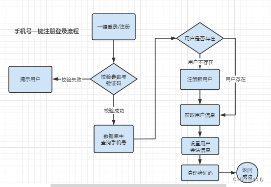
抖音实战~手机号一键注册登录流程(验证码)
Software engineering topics

数据智能基础设施升级窗口将至?看九章云极 DingoDB 如何击破数据痛点

Xidian AI ranked higher than Qingbei in terms of AI major, and Nantah ranked first in China in terms of Software Science in 2022
Tiktok practice ~ one click registration and login process of mobile phone number (verification code)

IPO配置指南

【无标题】#修复日志#

How to manage electronic documents efficiently and concisely

SQL编程task02作业-基础查询与排序
随机推荐
APM 飞行模式切换--源码详解
Record a time when Kali encounters vmtools button gray install vmtools
Quickly master asp Net authentication framework identity - login and logout
[Luogu] P1083 [NOIP2012 提高组] 借教室(差分)
Basic knowledge of AI Internet of things | community essay solicitation
Qt编写物联网管理平台36-通信协议
TCP建立连接过程(深入源码理解3次握手)
TikTok 宣布将数据存储于 Oracle 服务器!
Don't be silly enough to distinguish hash, chunkhash and contenthash
Pytorch实现波阻抗反演
thinkphp3.2.3日志包含分析
一口气读懂 IT发展史
Cache penetration tool "Bloom filter"
Introduction to code audit learning notes
SQL编程task04作业-集合运算
APM设置变桨距四旋翼控制模式
SQL编程task05作业-SQL高级处理
PAT甲级 - 1007 Maximum Subsequence Sum
MySQL中from_unixtime和unix_timestamp处理数据库时间戳转换问题-案例
[Luogu] P1083 [NOIP2012 提高组] 借教室(线段树)