当前位置:网站首页>LCD parameter interpretation and calculation
LCD parameter interpretation and calculation
2022-06-12 17:56:00 【_ kerneler】
https://blog.csdn.net/longxiaowu/article/details/24319933
Linux Kernel amba lcd Controller use clcd_panel The structure represents a LCD Hardware parameters of the screen :
/* include/linux/fb.h */
struct fb_videomode {

const char *name; /* optional */
u32 refresh; /* optional */
u32 xres;
u32 yres;
u32 pixclock;
u32 left_margin;
u32 right_margin;
u32 upper_margin;
u32 lower_margin;
u32 hsync_len;
u32 vsync_len;
u32 sync;
u32 vmode;
u32 flag;
};
/* include/linux/amba/clcd.h */
struct clcd_panel {

struct fb_videomode mode;
signed short width; /* width in mm */
signed short height; /* height in mm */
u32 tim2;
u32 tim3;
u32 cntl;
unsigned int bpp:8,
fixedtimings:1,
grayscale:1;
unsigned int connector;
};
Let's look at an example :http://lxr.linux.no/linux+v2.6.37.4/arch/arm/mach-lpc32xx/phy3250.c
fb_videomode The meaning of each parameter
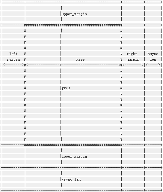
Linux Yes LCD The abstract of is shown in the following figure :
Let's study fb_videomode The meaning of each member :
Linux Kernel amba lcd Controller use clcd_panel The structure represents a LCD Hardware parameters of the screen :
-
/* include/linux/fb.h */
-
struct fb_videomode {
-
const
char *name;
/* optional */
-
u32 refresh;
/* optional */
-
u32 xres;
-
u32 yres;
-
u32 pixclock;
-
u32 left_margin;
-
u32 right_margin;
-
u32 upper_margin;
-
u32 lower_margin;
-
u32 hsync_len;
-
u32 vsync_len;
-
u32 sync;
-
u32 vmode;
-
u32 flag;
-
};
-
/* include/linux/amba/clcd.h */
-
struct clcd_panel {
-
struct fb_videomode mode;
-
signed
short width;
/* width in mm */
-
signed
short height;
/* height in mm */
-
u32 tim2;
-
u32 tim3;
-
u32 cntl;
-
unsigned
int bpp:
8,
-
fixedtimings:
1,
-
grayscale:
1;
-
unsigned
int connector;
-
};
| name | Abbreviation in the data book | Chinese name | significance | remarks |
| name | No | name | LCD name ( Optional ) | No |
| refresh | No | refresh frequency | refresh frequency ( Many examples in the kernel are assigned to 60) | No |
| xres | No | Line width | Number of pixels per row | No |
| yres | No | Screen height | The number of lines on the screen | No |
| pixclock | No | Pixel clock | The length of each pixel clock cycle , The unit is picosecond (10 Negative 12 In the second place 1 second ) | No |
| left_margin | HBP (Horizontal Back Porch) | Horizontal trailing edge | An image to be inserted at the beginning of the output of pixel data in each row or column Prime clock cycles | No |
| right_margin | HFP (Horizontal Front Porch ) | Horizontal frontier | At the end of each row or column of pixels LCD Line clock output pulse The number of pixel clocks between | No |
| upper_margin | VBP (Vertical Back Porch) | Vertical trailing edge | The number of invalid lines at the beginning of the frame after the vertical synchronization period | No |
| lower_margin | VFP (Vertical Front Porch) | Vertical leading edge | From the end of data output of this frame to the beginning of vertical synchronization cycle of the next frame Number of invalid lines before | No |
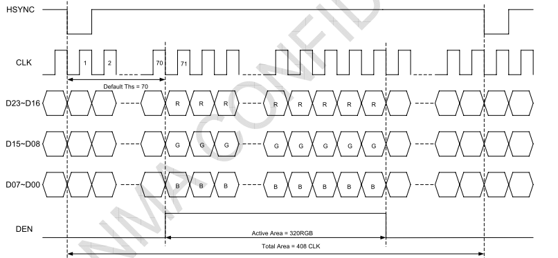
| hsync_len | HPW (HSYNC plus width) | Row synchronization pulse width | Company : Pixel clock cycle | There are also manuals called HWH(HSYNC width) |
| vsync_len | VPW (VSYNC width) | Vertical synchronous pulse width | Company : Show the time of one line th | There are also manuals called VWH(VSYNC width) |
| sync | No | Synchronous polarity setting | It can be set as needed FB_SYNC_HOR_HIGH_ACT( Horizontal synchronization high level is active ) and FB_SYNC_VERT_HIGH_ACT( Vertical sync high active ) | No |
| vmode | No | No | Most of the examples in the kernel are set directly to FB_VMODE_NONINTERLACED.interlaced It means to interlace [ Interlace ] scanning , Used in TV 2:1 Interleaving rate of , That is, each frame is divided into two fields , Two vertical scans , Scan odd rows in one field , Another field scans even lines . Obviously LCD This is not the current model . | No |
| flag | No | No | We haven't seen the usage at present | No |
#define TIM2_IVS (1 << 11) Reverse vertical synchronization The polarity of the signal .0: High active , Low level invalid .1: contrary
#define TIM2_IHS (1 << 12) Reverse horizontal synchronization The polarity of the signal .0: High active , Low level invalid .1: contrary
#define TIM2_IPC (1 << 13) To select whether the pixel data is driven to... On the rising or falling edge of the display clock LCD cable .0: Rising edge .1: Falling edge .
#define TIM2_IOE (1 << 14) This bit selects the effective polarity of the output enable signal .0: High active , Low level invalid .1: contrary
#define TIM2_BCD (1 << 26) Set this bit to 1, Make PCD The frequency division of is invalid . It is mainly used for TFT display . This bit is usually not set , Use the default value 0.
#define CNTL_LCDBPP1 (0 << 1) bit[1-3] Define color depth .bpp:bits per pixel, Number of bits per pixel .000 = 1 bpp.
#define CNTL_LCDBPP4 (2 << 1) 010 = 4 bpp.
#define CNTL_LCDBPP8 (3 << 1) 011 = 8 bpp.
#define CNTL_LCDBPP16 (4 << 1) 100 = 16 bpp
#define CNTL_LCDBPP16_565 (6 << 1) 110 = 16 bpp, 5:6:5 mode
#define CNTL_LCDBPP24 (5 << 1) 101 = 24 bpp (TFT panel only).
#define CNTL_LCDBW (1 << 4) STN LCD monochrome / Color selection .1: colour ,0: monochrome
#define CNTL_LCDTFT (1 << 5) LCD display TFT Type selection .0: STN display , Use the grayscale .1: TFT display , Do not use a grayscale scaler
#define CNTL_LCDMONO8 (1 << 6) This bit determines monochrome STN LCD It's using 4 Bit parallel interface or 8 Bit parallel interface .0:4 Bit interface .
#define CNTL_LCDDUAL (1 << 7) STN single LCD Display or dual LCD Display selection .0= Single screen
#define CNTL_BGR (1 << 8) Color mode selection ,0=RGB: Normal output ,1=BGR: Red and blue swap positions
#define CNTL_BEBO (1 << 9) Control the storage order of bytes in memory : 0= Small endian byte order ,1= Big endian byte order
#define CNTL_BEPO (1 << 10) Set how pixels are sorted ,0= Small end pixel sorting ,1= Use large pixel sorting
#define CNTL_LCDPWR (1 << 11) LCD Power enable .1=LCD The display is powered on and LCDV[23:0] Signal enable
#define CNTL_LCDVCOMP(x) ((x) << 12) LCD Vertical comparison is interrupted .00= The vertical sync pulse is active ,01= Start at the vertical back edge ,10= Valid video image start ,11= The vertical leading edge begins
#define CNTL_LDMAFIFOTIME (1 << 15) DMA FIFO Request delay
#define CNTL_WATERMARK (1 << 16) LCD DMA FIFO Waterline .0: When DMA FIFO contain 4 Or 4 When there are more than units above, a LCD DMA request .1:8 individual .


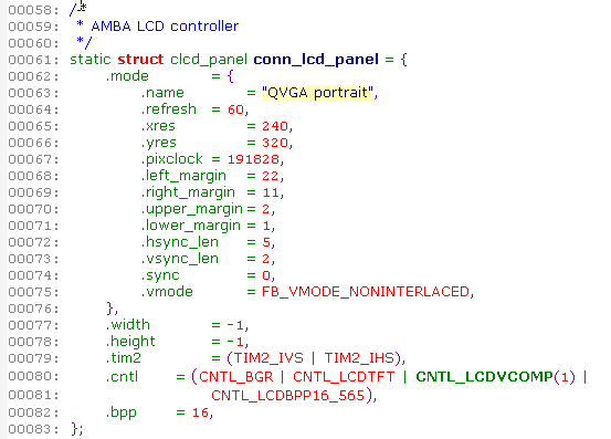
-
static
struct clcd_panel conn_lcd_panel = {
-
.mode = {
-
.name =
"QVGA TM035KDH03",
-
.refresh =
60,
-
.xres =
240,
-
.yres =
320,
-
.pixclock =
35714,
-
.left_margin =
69,
-
.right_margin =
18,
-
.upper_margin =
12,
-
.lower_margin =
10,
-
.hsync_len =
1,
-
.vsync_len =
1,
-
.sync = FB_SYNC_HOR_HIGH_ACT|FB_SYNC_VERT_HIGH_ACT,
-
.vmode = FB_VMODE_NONINTERLACED,
-
},
-
.width =
-1,
-
.height =
-1,
-
.tim2 =
0,
-
.cntl = ( CNTL_LCDTFT | CNTL_LCDVCOMP(
1) | CNTL_LCDBPP16_565),
-
.bpp =
16,
-
};
边栏推荐
- Click the list page of vant3+ts+pinia tab to enter the details. The tab on the details page is highlighted in the original position, and the refresh highlight is in the first item by default
- 一物一码追踪溯源系统介绍
- Reconnaître l'originalité de la fonction
- C# 业务流水号规则生成组件
- Vant3+ts H5 pages are nested into apps to communicate with native apps
- 用好IDE,研发效能提速100%
- 1.5 what is an architect (serialization)
- Figma从入门到放弃
- 一种好用、易上手的小程序IDE
- 企业架构的第一性原理
猜你喜欢

全局锁、表锁、行锁

Click the list page of vant3+ts+pinia tab to enter the details. The tab on the details page is highlighted in the original position, and the refresh highlight is in the first item by default

小程序+App,低成本获客及活跃的一种技术组合思路

First principles of enterprise architecture

SSM集成FreeMarker以及常用语法

es7不使用父子和嵌套关系来实现一对多功能

NixOS 22.05安装过程记录

vant3 +ts 封装简易step进步器组件

vant3+ts 封装uploader上传图片组件
Small program +app, a low-cost and active technology combination idea
随机推荐
認識函數原創
Lambda - 1
SSM integrates FreeMarker and common syntax
WinForm, crystal report making
USB转串口那些事儿—串口驱动类型
AlibabaProtect.exe如何删除、卸载
在同花顺开户证券安全吗
office应用程序无法正常启动0xc0000142
二分查找的理解
Codeforces Round #398 (Div. 2) D. Cartons of milk
Detailed description of SQL cursor and example of internal recycling
Schedule update | 2022 Microsoft and Intel hacker song competition is in hot registration
迄今微软不同时期发布的SQL Server各版本之间的大致区别,供参考查阅
Original error interface
USB转串口那些事儿—最大峰值串口波特率VS连续通信最高波特率
vant3 +ts 封装简易step进步器组件
73. 矩阵置零(标记法)
Goframe gredis configuration management | comparison of configuration files and configuration methods
关于数据集
利用小程序快速生成App,只需七步