当前位置:网站首页>51 single chip microcomputer ROM and ram
51 single chip microcomputer ROM and ram
2022-06-26 09:11:00 【Waves ~】
Tips : The following is the main body of this article , The following cases can be used for reference
One 、51 Program memory structure of single chip microcomputer
1. internal structure
The program memory inside the single chip microcomputer is used to store the program when the single chip microcomputer is working , There is a special one inside the single chip microcomputer 16 Bit program counter (PC), The program to be executed by the SCM at the next moment is ROM Address location in space , You can store 64Kb The size .
Program memory can be divided into on-chip program memory and off chip memory , Different single-chip computer models have different on-chip program memory space .
for example 8051 SCM chip has 4Kb Of ROM, When the control line takes 0 when ,PC Before accessing 4kb Space is in the film ROM; When the control line is 0 When ,PC The access is off chip ROM.
2. Of program memory 7 A special address
51 After the MCU is reset ,PC The content is 0000H, It is the starting address of the system program .
51 There are... Inside the single chip microcomputer 6 Broken source ,6 The descriptions and addresses of the interrupt sources are as follows :
Only interval between interrupt sources 8 Storage unit , This is not enough to store the interrupt program , So this is the interrupt entry address , Then there is the interrupt service function .
Two 、51 Data memory of single chip microcomputer
Data storage (RAM) Store the data needed during the operation of the single chip microcomputer and the temporarily generated data .
It is physically divided into on-chip RAM And off the film RAM( Off slice RAM It's through 16 Bit address bus access , So off the film RAM It's also 64kb).
1. On chip data storage
The manufacturer defines different task blocks according to different task requirements and requirements , As shown below :
Working register group : Altogether 32 Bytes , Also known as general purpose registers , For temporary deposit 8 Messages , The working register group is divided into 4 Two groups , Each group has R0-R7 altogether 8 Data information .
Bit addressing area : Altogether 16 Bytes ,128 position , Each bit in this area can be used in the way of location , this 128 Bit will reassign the working address .
commonly RAM Area : User programming can be used RAM, Of course , Unused space of the first two units , Users can also use it .
Stack area and stack pointer : First in, then out 、 A storage area managed on a last in first out basis
A function call is a stack operation , As shown in the figure below :
To implement the stack “ First in, then out , After the first out ” Data processing ,51 A stack pointer is set inside the MCU SP.
special function register : Dedicated to control 、 Manage on-chip arithmetic logic unit and other functional modules , The user can directly set the value for the special function register when programming .51 SCM internal includes PC , 19 A special function register , As shown below :
CPU Special register : accumulator A(E0H), register B(F0H), Program status register PSW(D0H), Stack register SP(81H), Data pointer DPTR(82H、83H)
2. Off chip data memory
51 Inside the MCU RAM When there's not enough space , Just expand off chip through the bus ram, It can be extended at most 64KB.
边栏推荐
- Behavior tree XML file hot load
- Chargement à chaud du fichier XML de l'arbre de comportement
- Computer mall based on SSM
- Solution to the encoding problem encountered by the crawler when requesting get/post
- [cloud primordial | kubernetes chapter] go deep into the foundation of all things - container (V)
- Self taught neural network series - 1 Basic programming knowledge
- Application of hidden list menu and window transformation in selenium
- Phpcms applet plug-in tutorial website officially launched
- How to set the shelves and windows, and what to pay attention to in the optimization process
- 修复小程序富文本组件不支持video视频封面、autoplay、controls等属性问题
猜你喜欢

phpcms v9去掉phpsso模块
![[Matlab GUI] key ID lookup table in keyboard callback](/img/b6/8f62ff4ffe09a5320493cb5d834ff5.png)
[Matlab GUI] key ID lookup table in keyboard callback

Notes on setting qccheckbox style
XSS cross site scripting attack

【300+精选大厂面试题持续分享】大数据运维尖刀面试题专栏(一)

《一周搞定数电》——组合逻辑电路

Upgrade phpcms applet plug-in API interface to 4.3 (add batch acquisition interface, search interface, etc.)

Vipshop work practice: Jason's deserialization application
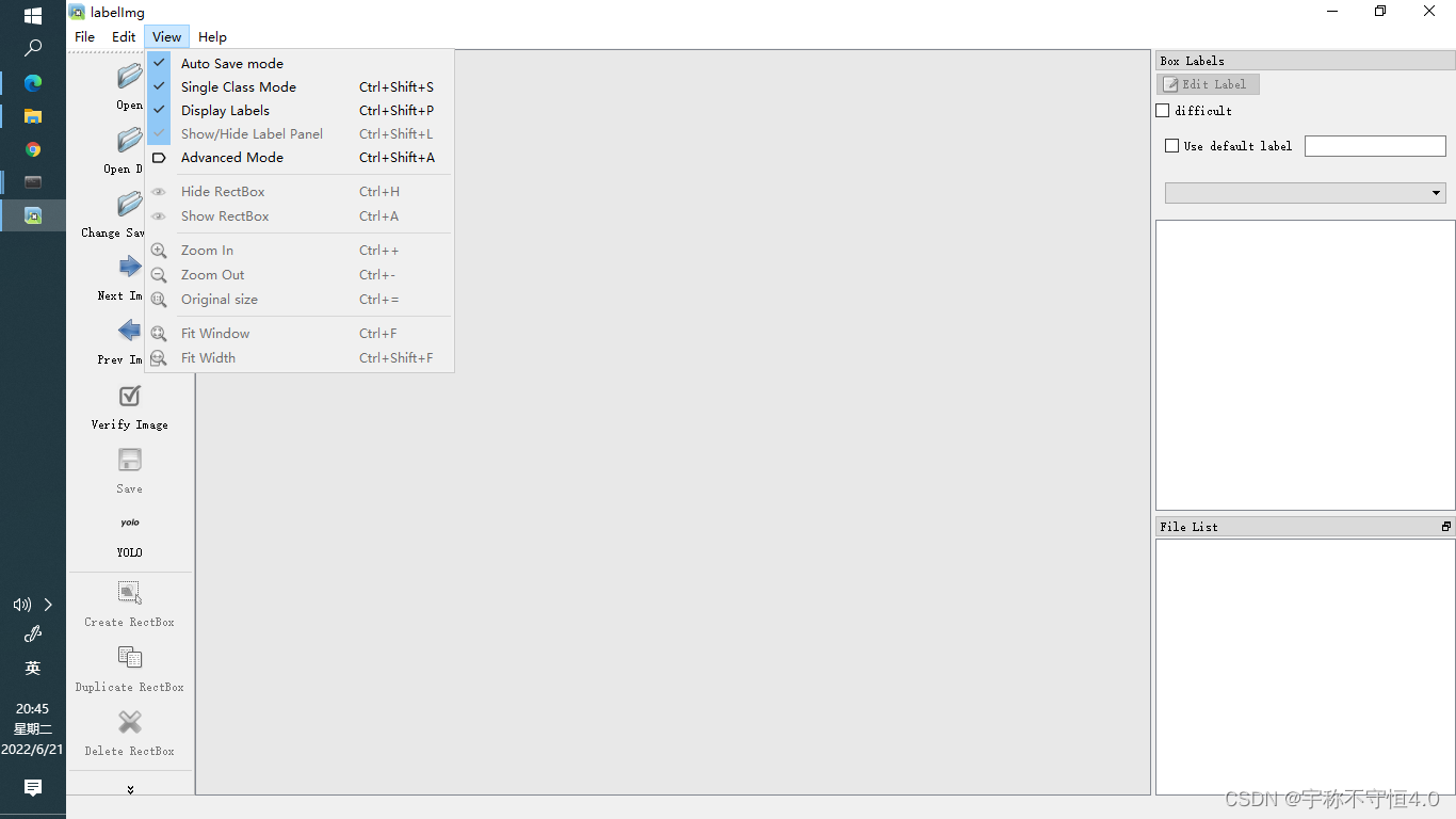
Yolov5 advanced level 2 installation of labelimg

【开源】使用PhenoCV-WeedCam进行更智能、更精确的杂草管理
随机推荐
How to handle the small program tabbar that does not support parameter transfer
PD快充磁吸移動電源方案
Differences between commonjs and ES6 modularity
ThreadLocal
Behavior tree XML file hot load
Li Kou 399 [division evaluation] [joint query]
Which software is safer to open an account on
Yolov5 advanced level 2 installation of labelimg
关于小程序tabbar不支持传参的处理办法
Self taught machine learning series - 1 basic framework of machine learning
[qnx hypervisor 2.2 user manual]12.1 terminology (I)
2021 software university ranking crawler program
Dedecms applet plug-in is officially launched, and one click installation does not require any PHP or SQL Foundation
行為樹XML文件 熱加載
ImportError: ERROR: recursion is detected during loading of “cv2“ binary extensions. Check OpenCV in
Docker install redis
Course paper: Copula modeling code of portfolio risk VaR
基于SSM的电脑商城
Vipshop work practice: Jason's deserialization application
Yolov5进阶之五GPU环境搭建