当前位置:网站首页>STM32 project design: temperature, humidity and air quality alarm, sharing source code and PCB
STM32 project design: temperature, humidity and air quality alarm, sharing source code and PCB
2022-06-26 08:22:00 【Turn into dust】
List of articles
2021 year 10 month 27-2022 year 1 month 1 Japan Can undertake single chip microcomputer design , Intentionally added Q2809786963
Baidu online data link :https://pan.baidu.com/s/1J6AuQpoDJbjMko3kSD4aZw
Extraction code :81f5
Take a like ~
One 、 subject
1、 use DHT11 The temperature and humidity sensor obtains the temperature and humidity information , According to the OLED On the screen
2、 use MQ-135 The air quality sensor obtains air quality information , According to the OLED On the screen
3、 Design an alarm system , The upper limit of temperature, humidity and air quality can be set , Beyond this value, the buzzer will give an audible alarm
Two 、 Prepare the material
( One )、 Master chip stm32f103c8t6 Core board 
( Two )DHT11 Temperature and humidity sensor 
( 3、 ... and )mq135 Air quality sensors 
( Four )4 The needle IIC OLED
3、 ... and 、 Schematic and PCB Design
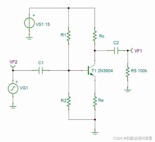
( One ) Schematic design 
( Two )PCB Design 
Four 、 Programming
( One )DHT11 drive
DHT11.c
#include "DHT11.h"
#include "delay.h"


//???DHT11
//??:??????(????)
u8 DHT11_Init()
{

	GPIO_InitTypeDef GPIO_InitStruce;
	RCC_APB2PeriphClockCmd(DHT11_DQ_RCC,ENABLE);		//????PA0

	GPIO_InitStruce.GPIO_Pin = DHT11_DQ_PIN;
	GPIO_InitStruce.GPIO_Mode = GPIO_Mode_Out_PP;
	GPIO_InitStruce.GPIO_Speed = GPIO_Speed_50MHz;
	GPIO_Init(DHT11_DQ_PORT,&GPIO_InitStruce);

	DHT11_Rst();

	return DHT11_Check();
}


//??DHT11
void DHT11_Rst(void)
{

    DHT11_IO_OUT(); 	//SET OUTPUT
    DHT11_DQ_OUT=0; 	//??DQ
    delay_ms(20);    	//????18ms
    DHT11_DQ_OUT=1; 	//DQ=1
    delay_us(30);     	//????20~40us
}


//??DHT11???
//??1:????DHT11???
//??0:??
u8 DHT11_Check(void)
{

   u8 retry=0;
   DHT11_IO_IN();//SET INPUT
   while (DHT11_DQ_IN&&retry<100)//DHT11???40~80us
   {

		retry++;
		delay_us(1);
   };
   if(retry>=100)return 1;
   else retry=0;
   while (!DHT11_DQ_IN&&retry<100)//DHT11????????40~80us
   {

       retry++;
	   delay_us(1);
   };
   if(retry>=100)return 1;
   return 0;
}


//?DHT11?????
//???:1/0
u8 DHT11_Read_Bit(void)
{

      u8 retry=0;
      while(DHT11_DQ_IN&&retry<100)//???????
      {

             retry++;
             delay_us(1);
       }
      retry=0;
      while(!DHT11_DQ_IN&&retry<100)//??????
       {

              retry++;
              delay_us(1);
         }
      delay_us(40);//??40us
      if(DHT11_DQ_IN)
		  return 1;
      else
		  return 0;
}


//?DHT11??????
//???:?????
u8 DHT11_Read_Byte(void)
{

    u8 i,dat;
    dat=0;
   for (i=0;i<8;i++)
  {

      dat<<=1;
     dat|=DHT11_Read_Bit();
    }
    return dat;
}


//?DHT11??????
//temp:???(??:0~50? humi:???(??:20%~90%)
//???:0,??;1,????
u8 DHT11_Read_Data(u8 *temp,u8 *humi)
{

    u8 buf[5];
    u8 i;
    DHT11_Rst();
    if(DHT11_Check()==0)
   {

          for(i=0;i<5;i++)//??40???
		{

			buf[i]=DHT11_Read_Byte();
		}
		if((buf[0]+buf[1]+buf[2]+buf[3])==buf[4])
		{

			*humi=buf[0];
			*temp=buf[2];
		}
	}else return 1;
	return 0;
}
DHT11.h
#ifndef __DHT11_H
#define __DHT11_H
#include "sys.h"

#define DHT11_IO_IN() {
      GPIOA->CRL&=0XFF0FFFFF;GPIOA->CRL|=8<<20;}
#define DHT11_IO_OUT() {
      GPIOA->CRL&=0XFF0FFFFF;GPIOA->CRL|=3<<20;}


#define DHT11_DQ_OUT PAout(5)
#define DHT11_DQ_IN PAin(5)

#define DHT11_DQ_RCC RCC_APB2Periph_GPIOA
#define DHT11_DQ_PIN GPIO_Pin_5
#define DHT11_DQ_PORT GPIOA

u8 DHT11_Init(void);
u8 DHT11_Read_Data(u8 *temp,u8 *humi);
u8 DHT11_Read_Byte(void);
u8 DHT11_Read_Bit(void);
void DHT11_Rst(void);
u8 DHT11_Check(void);

#endif
( Two )MQ-135 drive , Because it uses ADC, Go straight up ADC Code
#include "adc.h"
 #include "delay.h"

// initialization ADC
// Here we just take the regular channel as an example
// We will open the channel by default 0~3
void  Adc_Init(void)
{

	ADC_InitTypeDef ADC_InitStructure;
	GPIO_InitTypeDef GPIO_InitStructure;

	RCC_APB2PeriphClockCmd(RCC_APB2Periph_GPIOA |RCC_APB2Periph_ADC1	, ENABLE );	  // Can make ADC1 Channel clock


	RCC_ADCCLKConfig(RCC_PCLK2_Div6);   // Set up ADC Division factor 6 72M/6=12,ADC The maximum time cannot exceed 14M

	//PA1  As an analog channel input pin
	GPIO_InitStructure.GPIO_Pin = GPIO_Pin_1;
	GPIO_InitStructure.GPIO_Mode = GPIO_Mode_AIN;		// Analog input pins
	GPIO_Init(GPIOA, &GPIO_InitStructure);

	ADC_DeInit(ADC1);  // Reset ADC1

	ADC_InitStructure.ADC_Mode = ADC_Mode_Independent;	//ADC Working mode :ADC1 and ADC2 Working in independent mode
	ADC_InitStructure.ADC_ScanConvMode = DISABLE;	// Analog to digital conversion works in single channel mode
	ADC_InitStructure.ADC_ContinuousConvMode = DISABLE;	// A / D conversion works in single conversion mode
	ADC_InitStructure.ADC_ExternalTrigConv = ADC_ExternalTrigConv_None;	// The transformation is initiated by software rather than external triggers
	ADC_InitStructure.ADC_DataAlign = ADC_DataAlign_Right;	//ADC Data right alignment
	ADC_InitStructure.ADC_NbrOfChannel = 1;	// In order to change the rules ADC The number of channels
	ADC_Init(ADC1, &ADC_InitStructure);	// according to ADC_InitStruct The parameter specified in ADCx The register of


	ADC_Cmd(ADC1, ENABLE);	// Enable to designate ADC1

	ADC_ResetCalibration(ADC1);	// Enable reset calibration

	while(ADC_GetResetCalibrationStatus(ADC1));	// Wait for the reset calibration to finish

	ADC_StartCalibration(ADC1);	 // Turn on AD calibration

	while(ADC_GetCalibrationStatus(ADC1));	 // Wait for the calibration to finish

// ADC_SoftwareStartConvCmd(ADC1, ENABLE); // Enable to designate ADC1 Software conversion start function

}
// get ADC value
//ch: Value channel  0~3
u16 Get_Adc(u8 ch)
{

  	// Set the specified ADC The rule group channel for , A sequence , Sampling time
	ADC_RegularChannelConfig(ADC1, ch, 1, ADC_SampleTime_239Cycles5 );	//ADC1,ADC passageway , The sampling time is 239.5 cycle

	ADC_SoftwareStartConvCmd(ADC1, ENABLE);		// Enable to designate ADC1 Software conversion start function

	while(!ADC_GetFlagStatus(ADC1, ADC_FLAG_EOC ));// Wait for the conversion to finish

	return ADC_GetConversionValue(ADC1);	// Go back to the last time ADC1 Conversion result of rule group
}

u16 Get_Adc_Average(u8 ch,u8 times)
{

	u32 temp_val=0;
	u8 t;
	for(t=0;t<times;t++)
	{

		temp_val+=Get_Adc(ch);
		delay_ms(5);
	}
	return temp_val/times;
}
( 3、 ... and ) The main program
main.c Part of the code
int main(void)
 {

	  u16 key;
		int adc,cnt=0;
		float volt;
		delay_init();
		NVIC_Configuration();
		BEEP_Init();
		OLED_Init();
		OLED_Clear();
		uart_init(115200);
		printf(" Welcome to the dust health gadget \r\n");
		KEY_Init();
		LED_Init();
		TIM3_Int_Init(500-1,720-1);

		DEV_Init();


		OLED_Clear();
		OLED_Dis_Menu();
	while(1)
	{

		if(cnt++ ==1000)
		{

			cnt = 0;
			LED0=!LED0;
			adc =	Get_Adc_Average(0,5);
			volt = adc*3.3/4096;
			air = pow((3.4880*10*volt)/(5-volt),(1.0/0.3203));
			printf("air :%d\r\n",air);
			// Get temperature and humidity
			DHT11_Read_Data( &temp, &humi);
			if(last_temp!=temp || last_humi!=humi)
			{

				OLED_Dis_DHT(temp,humi,air);
			}
		}
		key = Key_GetValue();          // Key scan
		if(key)
		DealKeyVal(key);
		if(!KEY1_IO())
		{

				printf("%d\r\n",GetTime());
		}
		if(temp>Max_temp || humi>Max_humi || air>Max_air)
		{

			if(cnt<500)BEEP=1;
			else if(cnt<1000)BEEP=0;
		}else BEEP=0;


		delay_ms(1);
	}

}
边栏推荐
- MySQL practice: 4 Operation of data
- swift 代码实现方法调用
- Chapter VIII (classes and objects)
- Power apps application practice | easily develop employee leave attendance management applet with power apps
- Microcontroller from entry to advanced
- Idea uses regular expressions for global substitution
- Interview JS and browser
- 73b2d wireless charging and receiving chip scheme
- JS Date object
- Flume learning notes
猜你喜欢

JMeter performance testing - Basic Concepts

Baoyan postgraduate entrance examination interview - Network

Chapter 5 (array)
X-VLM多模态模型解读

ASP. Net and Net framework and C #

Chapter 4 (functions and preprocessing)

Idea auto Guide
Design of reverse five times voltage amplifier circuit

See which processes occupy specific ports and shut down

Calculation of decoupling capacitance
随机推荐
Use a switch to control the lighting and extinguishing of LEP lamp
Uniapp scrolling load (one page, multiple lists)
Vs2019-mfc setting edit control and static text font size
Comparison version number [leetcode]
RF filter
Pychart connects to Damon database
Detailed explanation of SOC multi-core startup process
Baoyan postgraduate entrance examination interview - operating system
Pic 10B parsing
Area of Blue Bridge Cup 2 circle
MySQL query time period
Project practice: parameters of pycharm configuration for credit card digital recognition and how to use opencv in Anaconda
SOC的多核启动流程详解
JS file message invalid character error
[issue 22] sheen cloud platform one side & two sides
swift 代码实现方法调用
STM32 encountered problems using encoder module (library function version)
h5 localStorage
Idea auto Guide
Uploading pictures with FileReader object