当前位置:网站首页>0 basic self-study STM32 (wildfire) -- use register to light LED -- Explanation of GPIO function block diagram
0 basic self-study STM32 (wildfire) -- use register to light LED -- Explanation of GPIO function block diagram
2022-06-29 17:20:00 【Fecter11】
What I use is wildfire stm32zet6( Overbearing development board ) in total 144 One pin , and stm32vet6( Guider development board ) yes 100 One pin .
Be careful GPIO Not a pin , The pin contains GPIO.
Pins such as VCC,GND,CLK wait 
So how to view the function of the pins ?
Find the official data book 
pin definition Is the definition of pin
high density high-density 
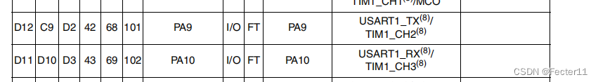
For example, the above two commonly used serial ports


Look from right to left
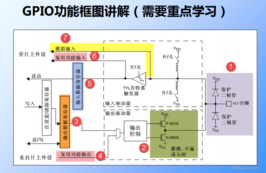
The first is the protective diode , Take the diode on the upper side as an example , If the input voltage is higher than vdd Diode on , take IO The voltage is clamped at 3.3V+ Range of clamping voltage , This protects the input .
For example :
If we want to connect a motor , The starting of the motor generates back electromotive force , The diode has not acted for a short time , So as to damage IO.
In addition, the current when starting is also very large .
So we should pay attention to when connecting the motor . Be sure to connect a drive circuit to isolate .
Push pull output :
What we do is 

Every time 4 One bit controls one GPIO
How to output it specifically 0 or 1 Of ??
Output control register by operation (ODR) To control MOS Output 3.3v or 0v.
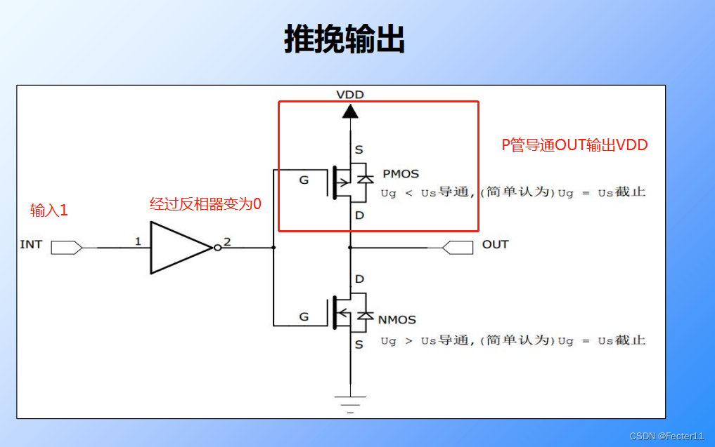

It is recommended to understand MOS tube N Tube and P The conduction condition of the tube .
The following figure shows the current flow of output high level , External output , Equivalent to pushing . This is also known as the current infusion , Inject current into the load .
The following figure shows the current flow of output low level , Equivalent to pulling . This is also called pull current .
MOS The internal resistance of the tube is very small , Push pull current can reach 25ma, It's bigger .
The following describes the open drain output
Open drain output can only output low level 

What is the meaning of open drain output ?
For example, we pass through IO There's another one out there 5v The peripherals of , We just need an external pull-up VDD Change it to 5V Level matching can be achieved .
Explain , Most of the above uses MOS tube
Complementary signals , Namely 1/0

The output data register corresponds to ODR
We can directly operate the output data register to achieve output 1/0
It can also be set for indirectly / Clear the write operation of the register to control the data output register to output 1/0
bit set / reset register This is it. BSRR
low 16 Position as set Set up 1
high 16 Position as rest clear 0
That is to say, if we are right BS0 and BR0 All written 1, The actual output is in BS0 Shall prevail or 1
There is also a register that can be implemented ODR Output reset operation 


Input data register Input data register 


This pull-up and pull-down is done by BSRR Register controlled ( In this part of the video, I didn't fully understand the specific implementation methods , Wait until later )
our IO When the input 3.3v All we can read from the register is 1/0. And Schmidt trigger , It's like a door ( I think it's just “ The threshold ”), higher than 2v Think it's high level , Output 1, lower than 1.2v It outputs 0
Input multiplexing function 
Here we add analog output 

边栏推荐
猜你喜欢


随机推荐
Word2vec vector model of Wiki Chinese corpus based on deep learning
In depth analysis of Monai (I) data and transforms
基于汇编实现的流载体的LSB隐藏项目
c# 国内外ORM 框架 dapper efcore sqlsugar freesql hisql sqlserver数据常规插入测试性能对比
“授权同意”落地压力大?隐私计算提供一种可能的合规“技术解”
SAAS 服务的优势都有哪些
MySQL触发器如何创建与删除
Freedom自由协议质押挖矿系统开发
基于深度学习的Wiki中文语料词word2vec向量模型
深圳内推 | 深圳计算科学研究院招聘机器学习助理工程师(校招)
About xampp unable to start MySQL database
Function calculation asynchronous task capability introduction - task trigger de duplication
可转债策略之---(摊饼玩法,溢价玩法,强赎玩法,下修玩法,双低玩法)
关于KALI使用xshell连接
Multi mode concurrent implementation of tortoise and rabbit race in go language
NVIDIA安装最新显卡驱动
【南京大学】考研初试复试资料分享
Calibration of monocular camera and binocular camera with kalibr calibration tool
Why is informatization ≠ digitalization? Finally someone made it clear
Which is better and safer, GF e-gold or Dongfang fortune