当前位置:网站首页>D2--FPGA SPI interface communication2022-08-03
D2--FPGA SPI interface communication2022-08-03
2022-08-05 07:54:00 【Xiaoxiao Muyu Xiaoxiao】
1.SPI简介
SPI是串行外设接口(Serial Peripheral Interface)的缩写,通常说SPI接口或SPIAgreement meansSPIThis is a serial peripheral interface specification.relative to the serial port,SPI是一种高速的(可达10Mb\s以上),全双工,同步的通信总线.A serial port is a point-to-point full-duplex asynchronous communication,Therefore, both parties to the communication should follow the same agreement(指起始、暂停位、波特率)to synchronize the data,communicate accurately.而SPIIt is a bus structure for synchronous communication,Synchronization means that a dedicated clock line is used to synchronize the source and destination,The bus structure refers to the master-slave distinction,Usually a device calls the shots,Can do from multiple devices,It is precisely because of thisCS片选线,Specifies the selected slave device.
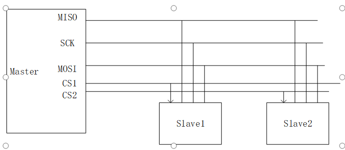
而在实际的应用中,Usually only one master and one slave.SPIThe interface is mostly usedFlash、ADC、LCD控制器,CMOSRegister configuration interface and other scenarios.SPI在芯片的管脚上只占用四根线,节约了芯片的管脚,同时为PCB的布局上节省空间,提供方便,正是出于这种简单易用的特性,越来越多的芯片集成了这种通信协议.
2.时序
SPI有四根线,如下,
(1)MISO– Master Input Slave Output,主设备数据输入,从设备数据输出;
(2)MOSI– Master Output Slave Input,主设备数据输出,从设备数据输入;
(3)SCLK – Serial Clock,时钟信号,由主设备产生;
(4)CS – Chip Select,从设备使能信号,由主设备控制.
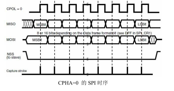
SPIThere are four timing modes for data transfer,This is determined by the properties of the device,用CPOL和CPHArepresent these four timings.CPOL是用来决定SCK时钟信号空闲时的电平,CPOL=0(1),空闲电平为低电平(高电平);CPHA是用来决定采样时刻的,CPHA=0,在每个周期的第一个时钟沿采样,CPHA=1,It is sampled on the second clock edge of each cycle.通常使用的是MODE0模式,即CPOL=CPHA=0,空闲时为低电平,Sampled on the first clock edge.Several other modes can be searched online if necessary,资料很多.
使用SPI接口时需要注意,很多SPIThe interface chip is not standardSPI协议,May be slightly changed,For example, there will be a clear description of which edge is sampled.此外,还有一种可能是在SPIFurther restrictions are made on the basis of the agreement,For example, after a read and write process is requiredCSMust be elevated.SPIRequirements come first,MSB的方式.还有就是SPIOne clock cycle must be performed to receive one bit of data and send one bit of data.
3.Dual、Qual模式
The above is the standardSPI,有4根引脚信号:clk , cs, mosi, miso.针对SPI Flash而言,有Dual SPI和Qual SPI两种模式,这是因为,FlashThe full duplex of the device is not commonly used,因此扩展mosi和miso的用法,让它们工作在半双工,用以加倍数据传输.也就是对于Dual SPI Flash,可以发送一个命令字节进入dual mode,这样mosi变成SIO0(serial io 0),mosi变成SIO1(serial io 1),这样一个时钟周期内就能传输2个bit数据,加倍了数据传输.与Dual SPI类似,Qual SPI Flash增加了两根I/O线(SIO2,SIO3),目的是一个时钟内传输4个bit.
4.Routine design and code interpretation
如图所示,把Spi_driverThe input and output of the module are divided into two parts,One part is the interface to interact with other modules on the left side of the diagram,The other part is connected to the physical pins on the right side of the figure.Spi_enThe signal is an external pulse signal,Execute once when this pulse is received8Bit的发送动作,和8Bitreceive action.通过VIO产生spi_ensignal and the data signal to be sentdata[7:0],将板卡上的mosi和miso管脚相连,Determine whether the sent data and the received data are consistent,Lights up if they matchled.Due to lack of beltSPIdevice board,Therefore, this routine is designed.Generated after a send action is completespi_done的脉冲信号,During the execution of the send action,spi_busyContinue to be pulled high.另外,spi_sckAs the synchronization clock directly determines the speed of data transmission,通常在10Mb/s以下,Or specified according to the peer device.
在使用SPIThis driver module can be modified to meet the needs of the equipment,The left signal interacts with the external device,当busySending is not allowed when pulled highspi_en信号;可以对dataThe signal uses a multiplexer,To complete some fixed instructions or read and write operations;同样,The bit width of the data can also be extended.另外,It should be used when actually using itcs管脚,Use this pin flexibly according to the requirements of the related equipment.
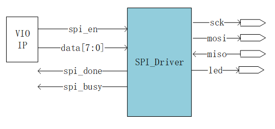
The following code completes the test on the hardware board.该代码使用MODE0,即CPOL=CPHA=0的模式.The procedure is divided into the following four steps,第一步产生sck同步时钟,第二步依据enIndicates the signal to write data,The third step is based onenIndicates the signal and reads the data concurrently,The fourth step is generatedui交互信号.
module spi_wr(
    input        clk_i       ,
    //user interface
    // input        spi_en     ,//其他模块的spi使能信号
    // input    [7:0]data      ,
    output       spi_busy      ,//指示spi的状态,表示SPI过程
    output       spi_done      ,//指示spiEnd an action
    output       led           ,
    // output       spi_cs        ,//SPI从机的片选信号,低电平有效.
    output       spi_clk       ,//主从机之间的数据同步时钟.
    output       spi_mosi      ,//数据引脚,主机输出,从机输入.
    input        spi_miso      //数据引脚,主机输入,从机输出.
    );
// assign spi_cs = 0;
//1.Synchronous clock generation module 用50MHz分频为50KHz
assign spi_clk = m_clk;
parameter [9:0] SPI_DIV    = 10'd499;//The frequency division is set to50KHz,50Mhz/50K/2- 1'b1=499
reg [9:0] clk_cnt = 10'd0;//分频计数器
[email protected](posedge clk_i)begin
    if(clk_cnt < SPI_DIV&&spi_busy)
        clk_cnt <= clk_cnt + 1'b1;
    else
        clk_cnt <= 10'd0;
end
reg m_clk = 1'b0;
[email protected](posedge clk_i)begin
    if(spi_en)
        m_clk <= 1'b0;
    else if(clk_cnt==SPI_DIV)
        m_clk <= ~m_clk;
end
//2.接收ensignals and data,执行spi mosi操作(写数据)
//Count the number of sending
reg [3:0]tx_cnt = 0;
[email protected](posedge clk_i)begin
    if(spi_en)begin
        tx_cnt <= 0;
    end else if((clk_cnt == SPI_DIV)&&(tx_cnt==4'd8))begin
        tx_cnt <= 0;
    end else if((clk_cnt == SPI_DIV)&&spi_clk==0)
        tx_cnt<=tx_cnt+1;
end
//Shift register transmission
wire [7:0]data;
reg  [7:0]data_reg=8'b0;//数据源
[email protected](posedge clk_i)begin
    if(spi_en)
        data_reg <= data;
    else if(spi_done)
        data_reg <=8'b0;
    else if(clk_cnt == SPI_DIV&&spi_clk==1)
        data_reg[7:0] <= {data_reg[6:0],data_reg[7]};
end
assign spi_mosi = data_reg[7];
//3.接收ensignals and data,执行spi miso操作(读数据)
reg  [7:0]data_fifo=8'b0;
[email protected](posedge clk_i)begin
    if((clk_cnt == SPI_DIV)&&spi_clk==0)begin
        case (tx_cnt)
           0 : data_fifo[7] <= spi_miso;
           1 : data_fifo[6] <= spi_miso;
           2 : data_fifo[5] <= spi_miso;
           3 : data_fifo[4] <= spi_miso;
           4 : data_fifo[3] <= spi_miso;
           5 : data_fifo[2] <= spi_miso;
           6 : data_fifo[1] <= spi_miso;
           7 : data_fifo[0] <= spi_miso;
           default: ;
        endcase
    end else
        data_fifo <= data_fifo;
end
//4.发出user interfacerelevant indication signals
wire spi_en;
reg spi_busy =0;
assign spi_done = ((clk_cnt == SPI_DIV)&&(tx_cnt==4'd8)) ? 1'b1 : 1'b0;
assign led = (data_fifo==8'b11010111) ? 1'b1 : 1'b0;
//产生busy信号,指示spi进程
[email protected](posedge clk_i)begin
    if(spi_en)
        spi_busy<=1'b1;
    else if(spi_done)
        spi_busy<=1'b0;
    else
        spi_busy<=spi_busy;
end

vio_0 use_vio (
  .clk(clk_i),                // input wire clk
  .probe_out0(spi_en),  // output wire [0 : 0] probe_out0
  .probe_out1(data)  // output wire [7 : 0] probe_out1
);
ila_0 your_instance_name (
    .clk(clk_i), // input wire clk
    .probe0({data_reg,data_fifo}), // input wire [15:0]  probe0
    .probe1(tx_cnt), // input wire [3:0]  probe1
    .probe2({spi_en,spi_mosi,spi_miso,spi_busy}) // input wire [3:0]  probe2
);边栏推荐
- C语言制作-QQ聊天室
- 程序设计中的感悟
- [Shanghai] Hiring .Net Senior Software Engineer & BI Data Warehouse Engineer (Urgent)
- MAYA船的建模
- Win10 设置锁屏壁纸提示尝试其它图片
- openSource 知:社区贡献
- A small problem with mysql using the in function
- 执子之手,与子偕老。你同意么?
- uniapp time component encapsulates year-month-day-hour-minute-second
- The magic weapon for small entrepreneurs!
猜你喜欢
【结构体内功修炼】结构体内存对齐(一)
busybox 知:构建
环网冗余式CAN/光纤转换器 CAN总线转光纤转换器中继集线器hub光端机

Re regular expressions

MongoDB 语法大全

D2--FPGA SPI接口通信2022-08-03
爬虫之验证码
In the anaconda Promat interface, import torch is passed, and the error is reported in the jupyter notebook (only provide ideas and understanding!)
配合屏幕录像专家,又小又清晰!
DeFi 前景展望:概览主流 DeFi 协议二季度进展
随机推荐
2006年星座运势全解-射手
In the anaconda Promat interface, import torch is passed, and the error is reported in the jupyter notebook (only provide ideas and understanding!)
C语言制作-QQ聊天室
TRACE32——Break
环网冗余式CAN/光纤转换器 CAN总线转光纤转换器中继集线器hub光端机
Mysql 死锁和死锁的解决方案
奇怪的Access错误
browserslist 选项的目的是什么?
谷歌零碎笔记之MVCC(草稿)
存储过程编写经验和优化措施
Task flow scheduling tool AirFlow,, 220804,,
uniapp time component encapsulates year-month-day-hour-minute-second
Redis 全套学习笔记.pdf,太全了
双向循环带头链表
cmake 学习使用笔记(三)
作为一个男人必须明白的22个道理
openSource 知:社区贡献
The magic weapon for small entrepreneurs!
唤醒手腕 - 微信小程序、QQ小程序、抖音小程序学习笔记(更新中)
D2--FPGA SPI接口通信2022-08-03