当前位置:网站首页>Brief introduction to common pigtails of communication pigtails
Brief introduction to common pigtails of communication pigtails
2022-06-22 02:08:00 【Software testing is important】
Introduction to common pigtails
You who have touched pigtails , I must have heard strange professional terms . Among them, the name of pigtail LC-LC、SC-LC、FC-FC、FC-SC Circle round , Stupid is not clear . In fact, these names are classified according to the joints of pigtails . Let's first understand the structure of optical fiber , After introducing the connector , I don't feel dizzy when talking about pigtails .
One 、 Optical fiber structure
The bare fiber of optical fiber is generally divided into three layers : A core made of transparent optical material 、 Cladding and coating
first floor : Fiber core , Glass core with high refractive index ( The core diameter is generally 9-10μm( Monomode ),50 or 62.5( multimode )).
The second floor : Cladding , Silicon glass cladding with low refractive index ( The diameter is generally 125μm), Form total reflection condition with fiber core .
The third level : Smart cover , The outermost layer is a resin coating for reinforcement , It has high strength , Able to withstand large impact , Play the role of protecting optical fiber .
The refractive index of the first layer n1 Greater than the refractive index of the second layer n2, Optical fiber communication uses the principle of total reflection , With the help of continuous total reflection , It can be conducted from one end to the other .
Two 、 Optical fiber transmission mode
According to the transmission mode of light in optical fiber, it can be divided into : Monomode (Single-Mode)( abbreviation :SM), multimode (Multi-Mode) ( abbreviation :MM) .
Single mode fiber : Single mode core diameter :9/125μm,10/125μm, The center glass core is thin ( The core diameter is generally 9 or 10μm), Cladding outer diameter (2b)=125μm, At a given operating wavelength , Only one mode of light , The intermodal dispersion is very small , Better stability . Single mode fiber is suitable for large capacity and long distance communication systems .
Multimode fiber : The central glass core is thick (50/125μm, European standard or 62.5/125μm, American Standard ), It can transmit multiple modes of light . But its inter mode dispersion is large , This limits the frequency of transmitting digital signals , And it will become more serious with the increase of distance . The distance of multimode optical fiber transmission is relatively close , Usually only a few kilometers . The transmission performance is worse than that of single-mode fiber .
Choice of pigtails : The pigtail of the corresponding connector is usually selected according to the optical module interface on the communication equipment , Then, according to the required pigtail length of the on-site construction scene , Choose the appropriate length of pigtails . Common pigtails are LC-LC 10m、SC-FC 20m、LC-FC 5m、FC-FC 20m(LC, Small square head ;FC, Round head ) wait .
The optical fiber connector is a detachable connector between optical fibers ( Activities ) Connected devices , It connects the two end faces of the optical fiber precisely , So that the optical energy output by the transmitting optical fiber can be coupled to the receiving optical fiber to the greatest extent , And minimize the impact on the system due to its involvement in the optical link , This is the basic requirement of optical fiber connector . Up to a point , Optical fiber connectors also affect the reliability and performance of optical transmission systems .
Connector model of pigtail
In practical application , We usually distinguish according to the different structures of optical fiber connectors . Here are some common optical fiber connectors : FC、SC、ST、LC、D4、DIN、MU、MT And so on . among ,ST Connectors are usually used for wiring equipment ends , Such as optical fiber distribution frame 、 Optical fiber module, etc ; and SC and MT Connectors are usually used for network devices . According to the end face shape of optical fiber, there are FC、PC( Include SPC or UPC) and APC; According to the number of fiber cores, there are single core and multi-core ( Such as MT-RJ) Points . Optical fiber connectors are widely used , There is a wide variety of .
FC type (“ Round head ”)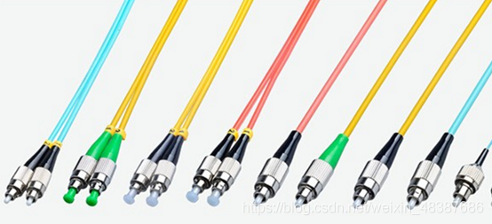
This kind of connector was first made in Japan NTT Development .FC yes ferrule Connector Abbreviation , It shows that the external strengthening method is metal sleeve , The fastening method is turnbuckle .FC Type is divided into FC/FC and FC/PC(APC) type , FC Type of connector , The plane butt joint of the adopted ceramic pin . This kind of connector has simple structure , It is easy to operate , Easy to make , But the fiber end is sensitive to dust , And it is easy to produce Fresnel reflection , It is difficult to improve the return loss performance . later , Improved this type of connector , Use a pin with a spherical butt end surface (PC) Physical Connection, Its butt end face is in physical contact , The end face is of convex arch structure , The performance of insertion loss and return loss is greatly improved .
SC type (“ Big square head ”)
This is a kind of Japanese NTT Optical fiber connector developed by the company .SC yes Square Connector Abbreviation , Its shell is rectangular . The end face of the pin is mostly PC or APC Type grinding method ; The fastening method is plug-in pin latch type , No rotation required . This kind of connector is cheap , Easy plugging operation , The fluctuation of intervention loss is small , High compressive strength , High installation density .
LC type (“ Small square head ”)
LC Type a connectors are well known BELL( bell ) Developed by the Institute , Modular jack with convenient operation (RJ) Made of latch mechanism .SC yes Lucent Connector Abbreviation , The sizes of the pins and sleeves used are common SC、FC And so on , by 1.25MM. This can improve the density of optical fiber connectors in the optical fiber distribution frame . at present , In single mode SFF aspect ,LC Types of connectors have actually taken the lead , Applications in multimode are also growing rapidly .
ST type (“ Round head ”)
ST (Straight Tip) Clip on round type ,ST F-type optical fiber connector is a kind of metal round head with spiral notch ,ST The head coupler has a protruding detent . Commonly used in optical fiber distribution frame , The shell is round , The fastening method is turnbuckle .( about 10Base-F In connection , Connectors are usually ST type . Commonly used in optical fiber distribution frame )
DIN47256 type 
This is a connector developed in Germany . The structural dimensions of the pin and coupling sleeve used in this connector are the same as that of FC Same type , The end face treatment adopts PC Grinding method . And FC Type connectors , Its structure is more complicated , There are springs in the internal metal structure to control the pressure , It can avoid damaging the end face due to excessive plugging pressure . in addition , This kind of connector has high mechanical accuracy , Therefore, the intervention loss value is small .
MT-RJ type 
MT-RJ Start from NTT Developed MT The connector , With and RJ-45 type LAN The same latch mechanism as the electrical connector , Align the optical fiber through the guide pins installed on both sides of the small sleeve , To facilitate connection to the optical transceiver , The optical fiber at the end face of the connector is double core ( interval 0.75MM) Arrangement design , It is the next generation of high-density optical fiber connector mainly used for data transmission .
3、 ... and 、 The cross section of the optical fiber connector shall be divided into PC、UPC、APC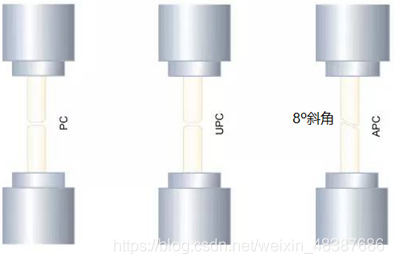
PC、APC、UPC Refers to the end face of the pin of the optical fiber connector , The difference lies in the workmanship of their connector heads and jumper losses ,UPC、APC The jumper is of fine workmanship 、 Low loss .
Return loss is a parameter of optical fiber performance . When the optical signal is transmitted in the optical fiber, it will encounter obstacles and be transmitted back to the signal transmitter , This is the echo , This is a phenomenon that is not conducive to optical fiber transmission , In order to eliminate this phenomenon , The return loss of optical fiber can eliminate the return . therefore , The larger the return loss is , The larger the echo that can be eliminated , The better the performance of the optical fiber .
PC(Physical Contact) The joint section is flat , Return loss is poor .
UPC(Ultra Physical Connectors) The joint is curved , The return loss of the industrial standard is 50dB~ 55dB.
APC(Angle Physical Connectors) section 8 Angle of inclination , To reduce reflection , The industrial standard return loss is >60dB.
Fiber attenuation
Optical fiber attenuation is an important factor that hinders the long-distance transmission of digital signals . The optical fiber loss directly affects the transmission distance or the distance between relay stations . The main factors causing optical fiber attenuation are : Intrinsic , bending , extrusion , impurities , Unevenness and butt joint, etc .
Intrinsic : Is the inherent loss of optical fiber , Include : Rayleigh scattering , Inherent absorption, etc .
bending : When the optical fiber is bent, some light in the optical fiber will be lost due to scattering , Cause loss .
extrusion : The loss caused by slight bending when the optical fiber is squeezed .
impurities : The impurities in the optical fiber absorb and scatter the light propagating in the optical fiber , Loss caused .
uneven : Loss caused by uneven refractive index of optical fiber materials .
docking : Loss caused by optical fiber docking , Such as : Different axes ( The coaxiality of single-mode fiber shall be less than 0.8μm), The end face is not perpendicular to the axis , The end face is uneven , Mismatch of butt center diameter and poor welding quality .
Loss of optical fiber
1310 nm : 0.35 ~ 0.5 dB/Km
1550 nm : 0.2 ~ 0.3dB/Km
850 nm : 2.3 ~ 3.4 dB/Km
Optical fiber fusion point loss :0.08dB/ spot
Optical fiber fusion point 1 spot /2km
Definition of common units in optical fiber communication :
dB = 10 lg ( Pout / Pin )
Pout : Output power ; Pin : Input power
dBm = 10 lg ( P / 1mw)
It is widely used in communication engineering ;
It is usually expressed in 1 Milliwatts as reference optical power ;
for example : –10dBm Indicates that the optical power is equal to 100uw.
dBu = 10 log10 ( P / 1uw)
边栏推荐
- es-object vs nested vs has_child and has_parent
- Ansible inventory host list
- Leetcode + 46 - 50
- Input系统学习-----InputFilter
- 【随笔】昨天研究了一天 RN 生态的 Expo 的确牛逼,从开发构建到部署一条龙,很好使。
- 微信小程序影视评论交流平台系统毕业设计毕设(2)小程序功能
- Wechat applet film and television review and exchange platform system graduation design completion (8) graduation design thesis template
- 微信小程序影視評論交流平臺系統畢業設計畢設(4)開題報告
- Who will use pyspark to upload filtered local data to spark SQL
- 微信小程序影视评论交流平台系统毕业设计毕设(1)开发概要
猜你喜欢

Lianfa science and technology -- Introduction to Lianfa science and technology ++ attached

Leetcode 41 - 45 dynamic planning topic
LeetCode 41 - 45 动态规划专题

Appium interview questions

acwing 836. Merge sets (merge sets)
![[chapter 06 MATLAB realizes lung cancer diagnosis based on watershed segmentation]](/img/2f/b2f141bf2f0b1f2f80444d37529a9b.png)
[chapter 06 MATLAB realizes lung cancer diagnosis based on watershed segmentation]

LeetCode+ 46 - 50

Chrome browser cancel input box to record form input history

Chapter 03 extraction of anterior segment tissue based on multi-scale morphology - full system matlab intelligent driving in-depth learning

GAMES-101-个人总结归纳-Rasterization
随机推荐
New employees enter the company and learn about work information
idea----bookmark
微信小程序影视评论交流平台系统毕业设计毕设(7)中期检查报告
【虚幻引擎UE】打包报错出现!FindPin错误的解决办法
Mysql数据库轻松学09—数据分析师常用:数据查询语言DQL之多表查询
Dachang NVIDIA face test questions sorting 123
Mba-day18 elimination method
啊哈C语言 第5章 好戏在后面(第24-25讲)
LeetCode+ 46 - 50
学习过的课程
[chapter 04 answer sheet recognition based on Hough change]
Common shortcut keys in Excel summary of shortcut keys in Excel
Mysql数据库轻松学07—select语句书写顺序及执行顺序
[essay] the Expo that studied the RN ecology for one day yesterday is really awesome. It works well from development and construction to deployment.
2021 CSP-J1 CSP-S1 第一轮 初赛 相关题解及视频等
acwing 836. Merge sets (merge sets)
Preliminary competition of noip improvement group III. problem solving exercise set noip1995-noip2018
Mathematical knowledge in the first round of noip preliminary round csp-j1 csp-s1 Sinorgchem (III)
LeetCode+ 46 - 50
Redis cache exceptions and handling scheme summary