当前位置:网站首页>VRRP+BFD
VRRP+BFD
2022-07-04 02:12:00 【Grey rain】
VRRP( Virtual router redundancy protocol )
The user terminal in LAN usually accesses the external network by configuring a default gateway , If the default gateway device fails at this time , The network access of all user terminals will be interrupted , This is likely to bring unpredictable losses to users , Therefore, the single point of failure problem can be solved by deploying multiple gateways , So how to make multiple gateways work together without conflict has become the most urgent problem to be solved . therefore VRRP emerge as the times require , It can realize the backup of gateway , It can also solve the problem of conflict between multiple gateways .
VRRP A basic overview of
VRRP It can be used without changing the networking , Virtual multiple routers into a virtual router , By configuring the IP The address is the default gateway , Backup the gateway .
Protocol version :VRRPv2( Commonly used ) and VRRPv3:
VRRPv2 Only applicable to IPv4 The Internet ,VRRPv3 Apply to IPv4 and IPv6 Two kinds of networks .
VRRP Protocol message :Advertisement message ; Its purpose IP The address is 224.0.0.18, Purpose MAC The address is 01-00-5e-00-00-12, The agreement number is 112.
VRRP Protocol state machine
Initialize( The initial state )、Master( Activity status )、Backup( Standby state ).
The transition conditions between the three states are as follows :
Initialize->Master:Startup priority=255;
Initialize->Backup:Startup priority!=255;
Master->Initialize: Device shut down ;
Master->Backup: Receive packets with higher priority than yourself ;
Backup->Initialize: Device shut down ;
Backup->Master: Not received within the timeout period VRRP Notification message or original message received Master The priority for 0, Or the original... In the received notification message Master The priority is lower than your own .
working process
Election out Master.
The state is maintained ,Master The device periodically sends VRRP Announce messages to other devices in the Group , To inform yourself that you are in a normal working state .
If Master failure ,Backup stay Master_Down_Interval Not received in time Master Status notification message sent , Immediately become Master.
If the original Master Fault recovery , Then the active / standby switchback .
Specific configuration
vrrp vrid 1 virtual-ip 10.0.0.10 // To configure vrid1 The virtual IP Address .
vrrp vrid 1 priority 120 // Configure in vrid1 The priority in is 120, Other device priorities are not specified manually , Default is 100, This equipment is Master.
vrrp vrid 1 preempt-mode timer delay 20 // To configure Master The preemption delay of the device is 20 second .
vrrp vrid 1 track interface GigabitEthernet0/0/0 reduce 30 // Trace uplink interface G0/0/0 The state of , If the port fails , be Master equipment VRRP Priority reduction 30.
Backup Device configuration :
vrrp vrid 1 virtual-ip 10.0.0.10 // To configure vrid1 The virtual IP Address .
BFD agreement
With the wide deployment of network applications , Network interruption may affect the normal operation of business and cause heavy losses . To reduce the link 、 The impact of equipment failure on business , Improve the reliability of the network , The network equipment needs to detect the communication failure with adjacent equipment as soon as possible , So as to take measures in time , To ensure the normal operation of the business .
Two way forwarding detection BFD(Bidirectional Forwarding Detection) It provides a general standardized medium independent and protocol independent fast fault detection mechanism , For rapid detection 、 Monitor the links in the network or IP Forwarding connectivity of routing .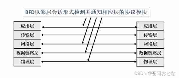
BFD After the session is established, it will be sent periodically and quickly BFD message , If the opposite end is not received within the detection time BFD The message thinks that the bidirectional forwarding path is faulty , Notify the relevant layer application being served to handle it accordingly .
There is no neighbor discovery mechanism in itself , Instead, the served upper layer application notifies its neighbor information to establish a session .
Regardless of the physical interface status 、 Layer 2 link status 、 Network layer address accessibility 、 Or transport layer connection status 、 Application layer protocol running status , Can be BFD Perceive .
Session creation process 
BFD Single arm echo function
It means passing through BFD The loopback operation of the message detects the connectivity of the forwarding link .
Two directly connected devices RTA and RTB, One of the devices RTA Support BFD function , Another device RTB I won't support it BFD function , Only basic network layer forwarding is supported . In order to quickly detect the fault between the two devices , Can be supported in BFD Functional devices RTA Create single arm echo function on BFD conversation .RTA Active echo request function , I won't support it BFD Functional devices RTB After receiving the message, directly loop it back , Thus, the connectivity detection function of the forwarding link is realized .
The technical principle of implementation is to support BFD Functional router RTA The destination address and source address of the outgoing interface are both their own BFD Probe message , I won't support it BFD Functional router RTB After receiving the detection message, it will be directly sent back to the router RTA.
Specific configuration
BFD And OSPF Linkage configuration implementation 
BFD And VRRP Linkage configuration implementation 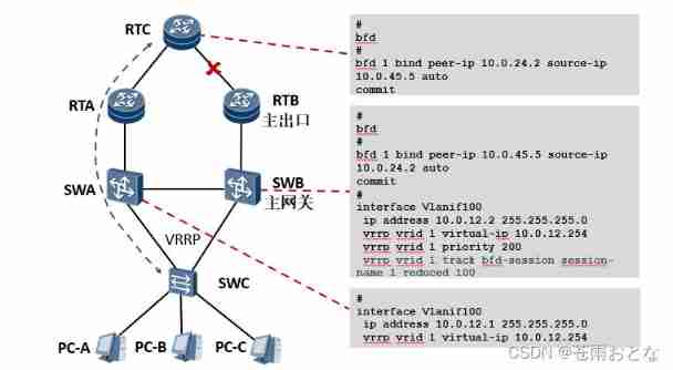
BFD Realize the linkage configuration with static routing 
BFD And BGP Linkage configuration implementation 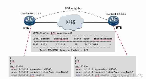
experiment
requirement 
This experiment simulates the gateway redundancy structure of a company , Complete the configuration according to the following requirements :
1. As shown in the figure , To configure R1/2/3 Equipment name and IP Address .
2. Internal and external network communication .
2.1 stay R1/2 Configure the default route on , Guarantee R1/2 Sure ping through R3 Of 3.3.3.3.
2.2 stay R1/2 On the configuration NAT, bring PC1/2 You can visit 3.3.3.3, Requirements are as follows :
1)acl The number is 2000, Use serial number 5 The rules of , Only allowed 192.168.1.0/24 Network segment .
2) Use eazy-ip Address translation , That is, configure the interface directly on the public network nat.
2.3 After completing the above steps , For the time being PC1 The gateway for is set to R1,PC2 The gateway for is set to R2.
2.4 Respectively in PC1 and PC2 On ping3.3.3.3, Ensure that internal and external networks can communicate .
3. Gateway Redundancy Protocol VRRP.
3.1 stay R1/2 Configure on the intranet interface of vrrp, fictitious IP The address is 192.168.1.254
3.2R1 The priority of 150,R2 Priority is the default priority .
3.3 Use display vrrp brief, Make sure R1 Be selected as Master,R2 by Backup.
3.4 take PC1/2 The gateway for is set to 192.168.1.254, And test whether it can work with 3.3.3.3 signal communication .
(VRRP Switching test :
3.5 take R1 Intranet interface G0/0/0 close , Use display vrrp brief command , Check the active / standby switchover .
3.6 test PC1/2 Whether you can communicate with 3.3.3.3 signal communication .
3.7 Reopen when finished R1 Of G0/0/0 Interface , And confirm R1 Become... Again Master.
3.8 The test again PC1/2 Whether you can communicate with 3.3.3.3 signal communication .)
4.VRRP Optimize .
When SW2 And R3 In case of link failure between ,R1 Can't perceive , It will cause the gateway not to switch .
4.1 stay R1/3 Upper opening BFD function
4.2R1 Create the name 1to3 Of BFD conversation , The target address is 13.1.1.3, The source address is 13.1.1.1, Auto generate flag .
4.3R3 Create the name 3to1 Of BFD conversation , The target address is 13.1.1.1, The source address is 13.1.1.3 , Auto generate flag .
4.4 stay R1/3 Upper use display bfd session all Command view bfd Conversation state .
4.5 stay R1 Of VRRP Middle tracking bfd conversation , When bfd Decrease when a link failure is detected 80 priority , Complete the active / standby switching .
( Switching test
4.6 When the configuration is complete , stay PC1/2 Use command on ping 3.3.3.3 -t, Then close it R3 Of g0/0/0 Interface , Observe vrrp Switching time .
4.7 After switching , stay R1 Upper use display vrrp command , Observe the priority changes .
4.8 Reopen R3 Of G0/0/0 Interface .
* Be careful : because SW2 No configuration ,R3 After the interface is opened ,SW2 Of G0/0/2 Need to carry out stp The election ,30s Only after the link is used .
4.9 wait for SW2 And R3 After the link is restored , see R1 Of BFD Conversation state , see R1 Of VRRP state .
4.10 The test again PC1/2 Whether you can communicate with 3.3.3.3 signal communication .)
answer
This experiment simulates the gateway redundancy structure of a company , Complete the configuration according to the following requirements :
1. As shown in the figure , To configure R1/2/3 Equipment name and IP Address .
A little
2. Internal and external network communication .
2.1 stay R1/2 Configure the default route on , Guarantee R1/2 Sure ping through R3 Of 3.3.3.3.
R1:ip route-static 0.0.0.0 0.0.0.0 13.1.1.3
R2:ip route-static 0.0.0.0 0.0.0.0 23.1.1.3
2.2 stay R1/2 On the configuration NAT, bring PC1/2 You can visit 3.3.3.3, Requirements are as follows :
1)acl The number is 2000, Use serial number 5 The rules of , Only allowed 192.168.1.0/24 Network segment .
R1/2:
acl number 2000
rule 5 permit source 192.168.1.0 0.0.0.255
2) Use eazy-ip Address translation , That is, configure the interface directly on the public network nat.
R1/2:
interface GigabitEthernet0/0/1
nat outbound 2000
2.3 After completing the above steps , For the time being PC1 The gateway for is set to R1,PC2 The gateway for is set to R2.
2.4 Respectively in PC1 and PC2 On ping3.3.3.3, Ensure that internal and external networks can communicate .
Self testing , A little
3. Gateway Redundancy Protocol VRRP.
3.1 stay R1/2 Configure on the intranet interface of vrrp, fictitious IP The address is 192.168.1.254
3.2 R1 The priority of 150,R2 Priority is the default priority .
R1:
interface GigabitEthernet0/0/0
vrrp vrid 1 virtual-ip 192.168.1.254
vrrp vrid 1 priority 150
R2:
interface GigabitEthernet0/0/0
vrrp vrid 1 virtual-ip 192.168.1.254
3.3 Use display vrrp brief, Make sure R1 Be selected as Master,R2 by Backup.
3.4 take PC1/2 The gateway for is set to 192.168.1.254, And test whether it can work with 3.3.3.3 signal communication .
(VRRP Switching test :
3.5 take R1 Intranet interface G0/0/0 close , Use display vrrp brief command , Check the active / standby switchover .
3.6 test PC1/2 Whether you can communicate with 3.3.3.3 signal communication .
3.7 Reopen when finished R1 Of G0/0/0 Interface , And confirm R1 Become... Again Master.
3.8 The test again PC1/2 Whether you can communicate with 3.3.3.3 signal communication .)
A little
4.VRRP Optimize .
When SW2 And R3 In case of link failure between ,R1 Can't perceive , It will cause the gateway not to switch .
4.1 stay R1/3 Upper opening BFD function
R1/3: bfd
4.2R1 Create the name 1to3 Of BFD conversation , The target address is 13.1.1.3, The source address is 13.1.1.1, Automatically generate bid
Zhi Fu .
R1: bfd 1to3 bind peer-ip 13.1.1.3 source-ip 13.1.1.1 auto
4.3R3 Create the name 3to1 Of BFD conversation , The target address is 13.1.1.1, The source address is 13.1.1.3 , Automatically generate bid
Zhi Fu .
R3: bfd 3to1 bind peer-ip 13.1.1.1 source-ip 13.1.1.3 auto
4.4 stay R1/3 Upper use display bfd session all Command view bfd Conversation state .
4.5 stay R1 Of VRRP Middle tracking bfd conversation , When bfd Decrease when a link failure is detected 80 priority , Complete the active / standby switchover
in .
interface GigabitEthernet0/0/0
vrrp vrid 1 track bfd-session session-name 1to3 reduced 80
( Switching test
4.6 When the configuration is complete , stay PC1/2 Use command on ping 3.3.3.3 -t, Then close it R3 Of g0/0/0 Interface , Observe
vrrp Switching time .
4.7 After switching , stay R1 Upper use display vrrp command , Observe the priority changes .
4.8 Reopen R3 Of G0/0/0 Interface .
* Be careful : because SW2 No configuration ,R3 After the interface is opened ,SW2 Of G0/0/2 Need to carry out stp The election ,30s after
Link can be used .
4.9 wait for SW2 And R3 After the link is restored , see R1 Of BFD Conversation state , see R1 Of VRRP state .
4.10 The test again PC1/2 Whether you can communicate with 3.3.3.3 signal communication .)
边栏推荐
- Global and Chinese market of small batteries 2022-2028: Research Report on technology, participants, trends, market size and share
- Mysql to PostgreSQL real-time data synchronization practice sharing
- Key knowledge of embedded driver
- Ceramic metal crowns - current market situation and future development trend
- Sword finger offer 14- I. cut rope
- [software implementation series] software implementation interview questions with SQL joint query diagram
- What are the main investment products of bond funds and what are they
- Measurement fitting based on Halcon learning [4] measure_ arc. Hdev routine
- mysql使用視圖報錯,EXPLAIN/SHOW can not be issued; lacking privileges for underlying table
- What are the advantages and disadvantages of data center agents?
猜你喜欢

Dans la recherche de l'intelligence humaine ai, Meta a misé sur l'apprentissage auto - supervisé
Example 072 calculation of salary it is known that the base salary of an employee of a company is 500 yuan. The amount of software sold by the employee and the Commission method are as follows: Sales

What is the student party's Bluetooth headset recommendation? Student party easy to use Bluetooth headset recommended
![[leetcode daily question] a single element in an ordered array](/img/3a/2b465589b70cd6aeec08e79fcf40d4.jpg)
[leetcode daily question] a single element in an ordered array

1189. Maximum number of "balloons"

MySQL advanced SQL statement (1)
Applet graduation project is based on wechat classroom laboratory reservation applet graduation project opening report function reference
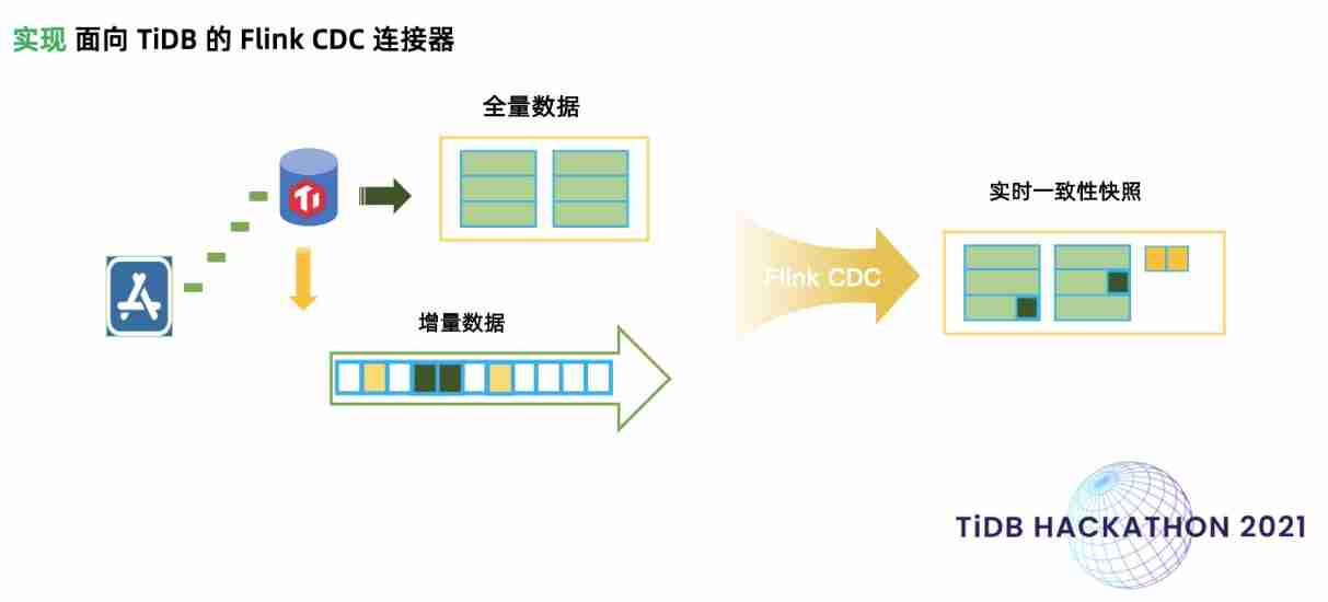
When tidb meets Flink: tidb efficiently enters the lake "new play" | tilaker team interview
![When the watch system of Jerry's is abnormal, it is used to restore the system [chapter]](/img/fb/7d4a026260f8817460cc67f06e49ae.jpg)
When the watch system of Jerry's is abnormal, it is used to restore the system [chapter]

Yyds dry goods inventory hand-in-hand teach you the development of Tiktok series video batch Downloader
随机推荐
G3 boiler water treatment registration examination and G3 boiler water treatment theory examination in 2022
14. Process time
C learning notes: C foundation - Language & characteristics interpretation
Software product download collection
Mysql-15 aggregate function
Global and Chinese market of cell scrapers 2022-2028: Research Report on technology, participants, trends, market size and share
Prose article appreciation - the rain in the warm country has never changed into cold, hard and brilliant flowers. Knowledgeable people think he is monotonous, and he thinks he is unlucky, doesn't he?
Small program graduation project based on wechat video broadcast small program graduation project opening report function reference
Learn these super practical Google browser skills, girls casually flirt
Will the memory of ParticleSystem be affected by maxparticles
Neo4j learning notes
Libcblas appears when installing opencv import CV2 so. 3:cannot open shared object file:NO such file or directory
FRP intranet penetration
1189. Maximum number of "balloons"
Feign implements dynamic URL
High level application of SQL statements in MySQL database (I)
Keep an IT training diary 054- opening and closing
2022 new examination questions for safety management personnel of hazardous chemical business units and certificate examination for safety management personnel of hazardous chemical business units
[Yugong series] February 2022 attack and defense world advanced question misc-84 (MySQL)
Yyds dry goods inventory it's not easy to say I love you | use the minimum web API to upload files