当前位置:网站首页>Qualcomm platform LCM summary
Qualcomm platform LCM summary
2022-06-22 07:29:00 【Neilo_ chen】
The following figures are the most recent examples of our own modules LCM Some conclusions of , At present, it is only partially completed , And the description is not particularly in place , It will be updated and modified in the future .
The first one is LCM Overall migration framework and component diagram . It introduces LCM The steps and key points of the driving segment and debugging screen .
branch lk and kernel Two parts , What exactly .c, How to add a new screen , General steps and methods .

The second figure is the initialization flow chart of the screen , It is divided into lk and kernel Two parts .Lk Part of it is as follows :
When the system is up, it will call bootable/bootloader/lk/app/aboot/aboot.c, In this function aboot_init() Function to call the display initialization function target_display_init(), Call... In this function gcdb_display_init().
One of the most important functions in this function is oem_panel_select(), It's defined in oem_panel.c in , It is based on Qualcomm's private code hw_id To decide which one you use LCD, And put panel Relevant data information is filled into the data structure --init_panel_data(),gcdb_display_init() After the execution of oem_panel_select() Be sure to use panel and panel After the relevant information , A series of values related to this are assigned through the function pointer panel Related functions , Include pll, Backlight ,clk, Initialization and enabling functions related to power supply , In order to call... Below .
meanwhile , Start execution A series of screen initialization processes . First step , Access to electricity , perform pdata->power_func, Open some ldo, Enable some system power , Pull it higher gpio, Make the screen powered , And do it on the screen inside reset, The function called is target_panel_reset(), In the face reset The pins are operated high and low . Then enable the clock , call pdata->clk_func, Then do some enabling pll, Distribute framebuffer, adopt fbcon_setup(&(panel->fb)) Function to set the global pointer such as the resolution and display address of the record display . Next into msm_display_config() Function for LVDS_PANEL,MIPI_VIDEO_PANEL,MIPI_CMD_PANEL Etc dsi and mipi To configure .
After some columns dsi Parameter set last call mdss_dsi_panel_initialize(), Use mdss_dsi_cmds_tx() towards lcm Of driver ic Sent initialization code . And decide , If target_panel_auto_detect_enabled() Open the conversation , Using the Qualcomm platform lcm read_id function mdss_dsi_read_panel_signature() Conduct id Read .
After completing this series of operations, execute msm_display_on(), Lighting screen , The last stage calls pdata->bl_func(1) Turn on the backlight . So the whole LK Of lcm Initialization is complete .LK The initialization flow chart of is as follows .

Next is kernel Stage LCM The initialization process .
kernel Stage , First, three platform devices will be registered in the driver ,msm_fb,mdp,mipi_dsi.mdp The module is Qualcomm's internal display control chip ,mipi_dsi It is a transport protocol layer device ,msm_fb It is the driving device of Qualcomm graphics card .
The first thing to execute is mdp Driven probe, Carry out hardware resources including clock , interrupt ,iommu, Bus ,DMA The initialization , Register some interfaces for fb Use of equipment .mdp Initialize after initialization dsi controller , stay mdss_dsi_ctrl_probe Function , A function was called mdss_ds_config_panel, In this function , Get by name matching panel Device node , If there is no match, call msm-mtp.dtsi Preset panel device node.
Next, execute the function dsi_panel_device_register() register panel_device Device node . In this register function , I'm sure it's DSI_VIDEO_MODE still MIPI_CMD_MODE, Obtained some resources such as gpio,regulatot,dsi-lane Relevant information , The important thing is that it registers a event_handler:mdss_dsi_event_handler, This event handler function will accept all kinds of... From other layers event Events include lighting , Turn off the screen, etc . Also through this event_handler,dsi Driver layer and fb layer ,mdp Layer to communicate .
And then execute mdss_dsi_panel_init Function panel The initialization . This function parses dtsi The file gets the name of the screen , The resolution of the , Physical dimensions ,dsi type ,porch Parameters , Color format , Initialization instruction , Backlight mode and other parameters , And fill them in one by one pinfo In this structure , And registered some on off , Set the backlight , Select operating functions such as mode . Next is mdss_fb Initialization of the device , stay mdss_fb_probe Function , By calling mfd->mdp.init_fnc To initialize mdp, adopt lcd_backlight_registered() To register the backlight driver .
When the system starts animation , Will call functions mdss_fb_open open fb controller , It's going to execute mdss_fb_blank_sub() And pass in FB_BLANK_UNBLANK event Parameters , perform mdss_fb_blank_unblank() function . In this function , By calling mfd->mdp.on_fnc() Yes mdp In drive on_fnc function , Namely mdp3_ctrl_on() function , This function moves forward dsi In drive event handler Send three events MDSS_EVENT_LINK_READY,MDSS_EVENT_UNBLANK,MDSS_EVENT_PANEL_ON call mdss_dsi_panel Driving medium mdss_dsi_on().
The configuration is executed inside dsi, Access to electricity ,reset, Send instructions to operate in a series to light up the screen . such kernel Part of the screen initialization is completed .
The picture below is KERNEL Initialization flow chart of the phase .

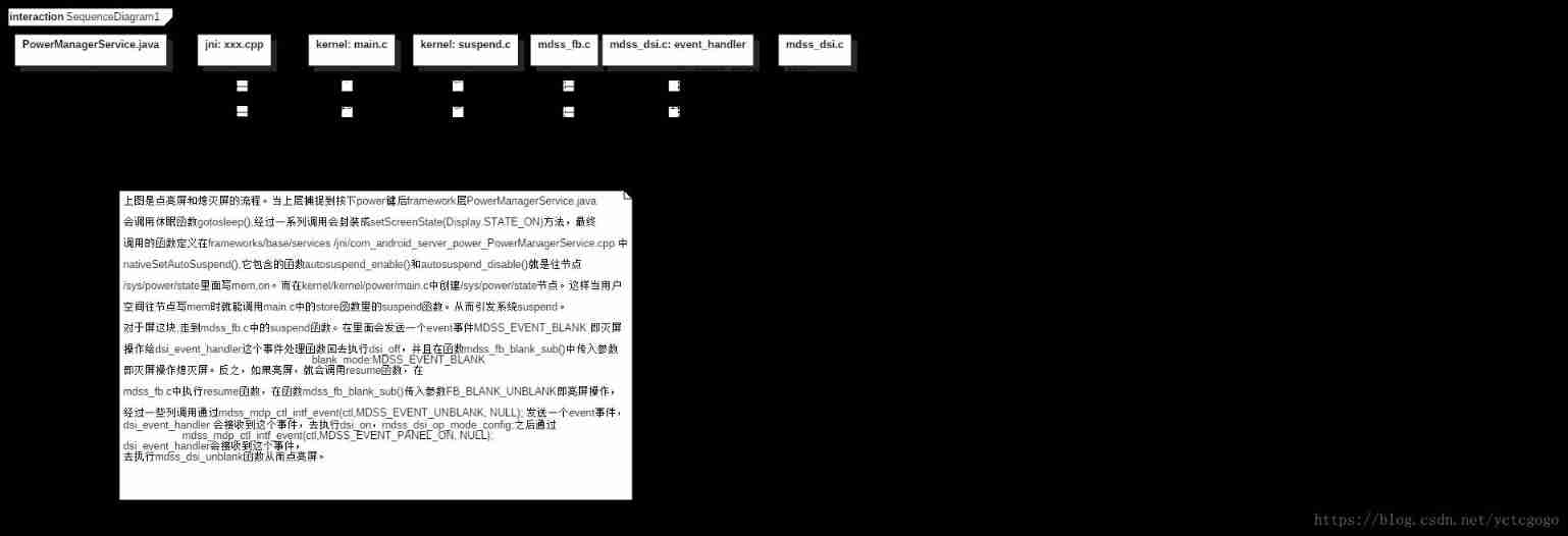
The fourth picture , It is the data transmission diagram of lighting screen and extinguishing screen from upper layer to bottom layer .
If you want to turn off the screen , The upper layer will call PowerManagerService Methods provided . The calling relationship of the whole process is goToSleep->goToSleepInternal-> updatePowerStateLocked->updateDisplayPowerStateLocked->
requestPowerState->sendUpdatePowerStateLocked->mHandler.sendMessage(msg)-> updatePowerState->animateScreenStateChange->setScreenState->scheduleScreenUpdate->
postScreenUpdateThreadSafe->mPhotonicModulator.setState->mLock.notifyAll-> mBlanker.requestDisplayState->initPowerManagement->callbacks.onDisplayStateChange->
setHalAutoSuspendModeLocked->nativeSetAutoSuspend
The last to nativeSetAutoSuspend() This local method , Is in
frameworks/base/services/jni/com_android_server_power_PowerManagerService.cpp
Called , Call the autosuspend_enable(), This function will go to /sys/power/state Node
mem.
This node , Is in kernel/kernel/power/main.c Created in sysfs The file nodes , Once a value is written into it, the corresponding store function . Off screen , The upper layer writes mem, Called store In the middle of suspend function , Then the system will go suspend technological process . Pass to the screen , stay msm_fb Call in system suspend function ,
After some column calls , Go to the mdss_fb_blank_blank(), call mfd->mdp.off_fnc, call mdp_ctrl.c
Of mdp_ctrl_off function , therefore panel->set_backlight(panel, 0) Turn off the backlight , By sending
MDSS_EVENT_BLANK to dsi In drive event_handler, call mdss_dsi_blank() Perform a series of operations to power off the screen . In this way, the whole screen extinguishing process is completed .
If the screen is on , Also from PowerManagerService Provide methods wake up, Finally call jni Of autosuspend_disable(), Go to /sys/power/state Node on, Last call suspend Process Lighting screen .
The flow chart is shown below .
Picture 5 , It summarizes how the backlight adjustment is transmitted from the upper layer to the bottom layer .
When the user is on the mobile phone setting-display-backlights When adjusting the backlight , The system will call
packages\apps\Settings\src\com\android\settings\BrightnessPreference.java To achieve . Set the brightness adjustment range here 0-255, adopt powermanagerservice.java The interface of setBrightness Implementation services . This method is defined in LightService.java in , call setBrightness()--->setLightLocked()--->setLight_native().
This local method is in frameworks\base\services\jni\com_android_server_LightsService.cpp achieve . Under this file ,init_native Function , call hw_get_module(LIGHTS_HARDWARE_MODULE_ID, (hw_module_t const**)&module) obtain lights Hardware abstraction layer module lights.default.so And load , call hall Layer function devices->lights[light]->set_light(devices->lights[light],&state) Set brightness .hall The code of the layer is hardware/qcom/display/liblight/lights.c.
In this, we have realized open_lights,close_lights,rgb_to_brightness Such as function . The key is , When adjusting the brightness , Will call the set_light_backlight(), adopt write_int Go to /sys/class/leds/lcd-backlight/brightness Write value . This file node is located in kernel Layer creation .kernel layer , stay Mdss_dsi_panel.c In the document , There is a backlight control function static void mdss_dsi_panel_bl_ctrl(struct mdss_panel_data *pdata,u32 bl_level), The parameter backlight value is through this bl_level For adjustment .
After one layer of call , In fact, kernel/drivers/leds/Led-class.c Created in the sysfs The file nodes /sys/class/leds/lcd-backlight/brightness, And in store Function , Save the current brightness value to led_cdev->brightness variable , Layer by layer to the drive bl_level. such , The transmission of backlight adjustment values from the upper layer to the bottom layer is formed .

The above pictures , In general, it summarizes LCM The driving part and some upper level relations , technological process . This sort of arrangement is quite helpful for your understanding and familiarity with the module . With the deepening of the work , I will continue to supplement and improve this document , Hope to achieve good results in practical work .
边栏推荐
- JS 数组扁平化 (递归写法)
- IDEA连接不到SQLSSMS
- Taobao assistant can not be used. How to export the baby in the warehouse to backup the data package
- Parameter curve notes of coursera self driving car Part4 motion planning
- Examples of Algebra: understanding of normal subgroups and quotient groups
- Self attention (notes, for personal use)
- Crmeb mall order shipping function
- Site pre cache code
- MySQL面试真题(二十)——视频数据分析实战
- Téléchargement de toutes les versions de chromedriver
猜你喜欢

Greek alphabet - system / service name commonly used in development - Collection

Crmeb mall distribution function
How to cancel crmeb customer service link

校招路上的坑

Reasons and solutions for Taobao's baby's prompt "sales attribute is required and parameter format is wrong"

Chromedriver所有版本下載

How to authorize a picture in a store to another store? What are the methods of unauthorized replication

MySQL面试真题(十八)——经营分析实战

JS implementation of random generation of 16 bit key -- Basic accumulation
希腊字母 - 开发中常用的系统/服务名 - 收集
随机推荐
Batch collection, grab Taobao baby, upload and collect commodity software
Taobao assistant can not be used. How to export the baby in the warehouse to backup the data package
架构图颜色搭配
Vue failed to connect to MySQL database
Greek alphabet - system / service name commonly used in development - Collection
Open version - order delivery
Lean production | lean management
What if the finder fails to respond continuously? Finder unresponsive solution tutorial
Open source get through version - integral function
Error e: unable to locate package sudo
How to backup the treasures in the store and upload them to multiple stores
报错 E: Unable to locate package sudo
Flutter black triangle
Taobao store backup one store upload to multiple stores precautions
3、 Stylesheet component
5g NR PWS system
MySQL面试真题(二十)——视频数据分析实战
Set the way that liquid (Jekyll) is displayed in markdown but not parsed
飞桨框架v2.3发布高可复用算子库PHI:重构开发范式,降本增效
网站如何提高百度权重