当前位置:网站首页>Bluetooth health management device based on stm32
Bluetooth health management device based on stm32
2022-06-27 09:33:00 【InfoQ】
1. Preface


2. Function summary
3. Hardware selection
3.1 MPU6050 gyroscope

3.2 STM32 Development board

3.3 Female to female DuPont line

3.4 Temperature sensor

 Communication protocol
 Serial port sends command bytes :

(1)、 Serial communication parameters ( Default baud rate value 9600 bps, It can be set by software )
 Baud rate :9600 bps  Check bit :N  Data bits :8  Stop bit :1

 Baud rate :115200 bps  Check bit :N  Data bits :8  Stop bit :1

(2)、 Module input commands , Sent by external controller to GY-MCU90615 modular ( Hexadecimal )

 1、 Frame head :0xa5

 Command format : Frame head + Instructions + The checksum (8bit)( Such as automatically reading the temperature command =0xA5+0x45+0xEA)

2、 Command instruction :

 Continuous output instruction :0xA5+0x45+0xEA---------------- Temperature data ( The data type returned by the module is 0x45)

 Query output instruction :

0xA5+0x15+0xBA --------------- Temperature data ( The data type returned by the module is 0x45)

 Configuration instructions :( It takes effect after power failure and restart )

 Baud rate configuration :

0xA5+0xAE+0x53 ---------------9600( Default )

0xA5+0xAF+0x54 ---------------115200

 Whether to automatically send temperature data configuration when powered on :

0xA5+0x51+0xF6--------------- Automatically output temperature data after power on ( Default )

0xA5+0x52+0xF7--------------- No automatic output of temperature data after power on


 Communication protocol

 A serial port to receive :

(1)、 Serial communication parameters ( Default baud rate value 9600 bps, It can be set by software )

  Baud rate :9600 bps  Check bit :N  Data bits :8  Stop bit :1

 Baud rate :115200 bps  Check bit :N  Data bits :8  Stop bit :1


(2)、 Module output format , Each frame contains 9 Bytes ( Hexadecimal ):

 ①.Byte0: 0x5A  Frame header flag

 ②.Byte1: 0x5A  Frame header flag

③.Byte2: 0X45  Data type of this frame (0X45: Temperature data )

 ④.Byte3: 0x04  Data volume ( following 4 Data 2 Group as an example )

 ⑤.Byte4: 0x00~0xFF  data 1 high 8 position

 ⑥.Byte5: 0x00~0xFF  data 1 low 8 position

 ⑦.Byte6: 0x00~0xFF  data 2 high 8 position

⑧.Byte7: 0x00~0xFF  data 2 low 8 position

⑨.Byte8: 0x00~0xFF  The checksum ( Previous data accumulation and , Leave only low 8 position )

(3)、 Data calculation method

 Temperature calculation method  :

 temperature =  high 8 position <<8  low 8 position ( The result is the actual angle multiplied by 100)

  example : Send instructions :A5 45 EA , Received a frame of data :

<5A- 5A- 45- 04- 0C- 78- 0D- 19- A7 >

  Express TO( A signed 16bit, Indicates the target temperature ):TO=0x0C78/100=31.92 ℃

  Express TA( A signed 16bit, Represents the ambient temperature ):TO=0x0D19/100=33.53 ℃

 Usage method
 This module outputs data for serial port , After the user connects through the serial port , Send output instructions , for example 0xA5+0x45+0xEA To module , The module will continuously output temperature data ; If you want to query the output, you can send 0xA5+0x15+0xBA To module , Every time it's sent , The module will return temperature data once , The query frequency should be less than 10hz, If higher than 10hz Please use continuous output mode , Send 0xA5+0x45+0xEA Instructions ;
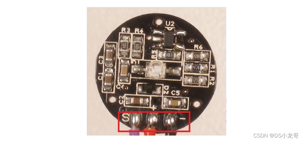
3.5 Pulse sensor


3.6 PCB Hole board

3.7 BLE Low power Bluetooth module

4. PC programming
4.1 development environment


4.2 Design effect

5. STM32 Development
5.1 Hardware wiring
 The hardware wiring instructions of this design :
(1)BLE Low power Bluetooth module
PA2(TX)--RXD  Module receiving pin
PA3(RX)--TXD  Module sending pin
GND---GND  The earth
VCC---VCC  Power Supply (3.3V)

(2) Infrared temperature measurement module
PB10(TX)--RXD  Module receiving pin
PB11(RX)--TXD  Module sending pin
GND---GND  The earth
VCC---VCC  Power Supply (3.3V)

(3)MPU6050 gyroscope
1 VCC 3.3V/5V  Power input  ----> Pick up 3.3V
2 GND  Ground wire  ---> Pick up GND
3 IIC_SDA IIC  Communication data line  -->PB6
4 IIC_SCL IIC  Communication clock line  -->PB7
5 MPU_INT  Interrupt output pin  ----> Unanswered
6 MPU_AD0 IIC  Slave address setting pin --> Unanswered
 AD0 Pin description :ID=0X68( In the air / Pick up  GND) ID=0X69( Pick up  VCC)

 (4) Heart rate detection module
PA1--- Heart rate module DAT Output pin
GND---GND  The earth
VCC---VCC  Power Supply (3.3V)


(--) On board LED The lamp : Low level light
LED1--PC13
BEEP2--PC14

(--) Onboard keys :
KEY1--PA0  Press to high level
5.2 Program download

5.3 System schematic diagram

5.4 keil engineering


5.5 Function code
#include "stm32f10x.h"
#include "delay.h"
#include "led.h"
#include "key.h"
#include "sys.h"
#include "usart.h"
#include <string.h>
#include <stdlib.h>
#include "timer.h"
#include "adc.h"
#include "mpu6050.h"
/*--------- Heart rate related data values ---------------*/
extern int IBI; // Adjacent beat time
extern int BPM; // Heart rate
extern int Signal; // Raw signal value
extern unsigned char QS; // Found heartbeat sign
short aacx,aacy,aacz; // Acceleration sensor raw data
short gyrox,gyroy,gyroz; // Gyroscope raw data
float TO=0; // Infrared temperature measurement - Target temperature
float TA=0; // Infrared temperature measurement - Object temperature
// Bluetooth send buffer
u8 BLE_TX_BUFF[100];
/*
The main function : The entry of program execution
*/
int main(void)
{
u32 i=0;
u8 key_val;
u32 wifi_TimeCnt=0;
JTAG_Set();
USART1_Init(115200); // A serial port 1 The initialization
USART2_Init(9600); // A serial port - bluetooth
TIMER2_Init(72,20000); // Timeout time 20ms
USART3_Init(9600); // A serial port - Infrared temperature measurement module
TIMER3_Init(36,20000); // Timeout time 20ms
// On board button initialization
KEY_Init();
// On board LED Lamp initialization
LED_Init();
//ADC initialization
ADC_Init();
// Timeout time 2ms
TIMER1_Init(72,2000);
// initialization MPU6050
while(MPU6050_Init())
{
printf(" Three axis accelerometer 、 Gyro initialization failed !\r\n");
DelayMs(1000);
}
printf(" The system works normally ..\r\n");
while(1)
{
// Onboard key detection
key_val=KEY_GetValue();
if(key_val)
{
printf(" Press the key ...\r\n");
}
// Time record
DelayMs(10);
wifi_TimeCnt++;
if(wifi_TimeCnt>=100) //1000 One millisecond
{
wifi_TimeCnt=0;
LED1=!LED1;
MPU6050_Get_Gyroscope(&gyrox,&gyroy,&gyroz); // Get the original data of the gyroscope
MPU6050_Get_Accelerometer(&aacx,&aacy,&aacz); // Get the acceleration sensor data
printf(" Three axis gyroscope :x=%d y=%d z=%d\r\n",gyrox,gyroy,gyroz);
printf(" Triaxial acceleration :x=%d y=%d z=%d\r\n",aacx,aacy,aacz);
printf("( heart rate )BPM=%d\r\n",BPM);
// Send data to Bluetooth , Send it to the upper computer
// for example : update,12,13,14,15,20.5
// respectively : The acceleration X Axis , The acceleration Y Axis , The acceleration Z Axis , heart rate 、 Temperature
sprintf((char*)BLE_TX_BUFF,"update,%d,%d,%d,%d,%f",aacx,aacy,aacz,BPM,TO);
USARTx_StringSend(USART2,(char*)BLE_TX_BUFF);
}
// Receive the data returned by Bluetooth
if(USART2_RX_FLAG)
{
USART2_RX_BUFFER[USART2_RX_CNT]='\0';
printf(" Bluetooth receives data :\r\n");
// The data returned to the serial port print server
for(i=0;i<USART2_RX_CNT;i++)
{
printf("%c",USART2_RX_BUFFER[i]);
}
USART2_RX_CNT=0;
USART2_RX_FLAG=0;
}
// Receive the data received by the infrared temperature measurement module in real time
if(USART3_RX_FLAG)
{
printf("\r\n Infrared temperature measurement starts :");
for(i=0;i<USART3_RX_CNT;i++)
{
printf("%#x ",USART3_RX_BUFFER[i]);
}
printf(" End of infrared temperature measurement .\r\n");
u8 sum=0,i=0;
for(sum=0,i=0;i<(USART3_RX_BUFFER[3]+4);i++)
{
sum+=USART3_RX_BUFFER[i];
}
/*
Temperature calculation method :
temperature = high 8 position <<8| low 8 position ( The result is the actual angle multiplied by 100)
example : Send instructions : A5 45 EA , Received a frame of data : <5A- 5A- 45- 04- 0C- 78- 0D- 19- A7 >
Express TO( A signed 16bit, Indicates the target temperature ): TO=0x0C78/100=31.92 ℃
Express TA( A signed 16bit, Represents the ambient temperature ): TO=0x0D19/100=33.53 ℃
*/
if(sum==USART3_RX_BUFFER[i])// Checksum judgment
{
TO=(float)((USART3_RX_BUFFER[4]<<8)|USART3_RX_BUFFER[5])/100.0; // Get the real temperature
TA=(float)((USART3_RX_BUFFER[6]<<8)|USART3_RX_BUFFER[7])/100.0; // Get the real temperature
}
printf("TO: %f\r\n",TO);
printf("TA: %f\r\n",TA);
memset(USART3_RX_BUFFER,0,sizeof(USART3_RX_BUFFER));
USART3_RX_CNT=0;
USART3_RX_FLAG=0;
}
}
}
边栏推荐
- Hitek power supply maintenance X-ray machine high voltage generator maintenance xr150-603-02
- js的数组拼接「建议收藏」
- MySQL proficient-01 addition, deletion and modification
- Object contains copy method?
- Some considerations on operation / method overloading for thread to release lock resources
- Quick start CherryPy (1)
- 我大抵是卷上瘾了,横竖睡不着!竟让一个Bug,搞我两次!
- [system design] proximity service
- Rman-08137 main library failed to delete archive file
- Installation and usage of source insight tool
猜你喜欢

Preliminary understanding of pytorch

Quelques exercices sur les arbres binaires

The markdown plug-in of the browser cannot display the picture

Getting started with webrtc: 12 Rtendpoint and webrtcendpoint under kurento

The largest rectangle in the bar graph of force buckle 84

C # solve the relative path problem using SQLite

Obsidian 一周使用心得(配置、主题和插件)
反编译jar包,修改后重新编译为jar包

提高效率 Or 增加成本,开发人员应如何理解结对编程?

Oracle uses an SQL to find out which data is not in a table
随机推荐
Object contains copy method?
不容置疑,这是一个绝对精心制作的项目
How do I get the STW (pause) time of a GC (garbage collector)?
HiTek电源维修X光机高压发生器维修XR150-603-02
冒牌构造函数???
IMX8QXP DMA资源和使用(未完结)
E+h secondary meter repair pH transmitter secondary display repair cpm253-mr0005
JS 文件上传下载
The background prompt module for accessing fastadmin after installation does not exist
ucore lab4
我大抵是卷上瘾了,横竖睡不着!竟让一个Bug,搞我两次!
高等数学第七章微分方程
Markem Imaje Marken IMAS printer maintenance 9450e printer maintenance
谷歌浏览器 chropath插件
Semi-supervised Learning入门学习——Π-Model、Temporal Ensembling、Mean Teacher简介
ucore lab4
多個類的設計
支付宝微信支付业务流程图
Digital ic-1.9 understands the coding routine of state machine in communication protocol
Pakistani security forces killed 7 terrorists in anti-terrorism operation