当前位置:网站首页>Drive brushless DC motor based on Ti drv10970
Drive brushless DC motor based on Ti drv10970
2022-07-05 14:34:00 【No martial arts, no understanding of the Jianghu】
Preface
I took over a project in the laboratory before , Need to use TI Of DRV10970 Chip to drive brushless DC motor with Hall feedback , The motor has been switched on these days , So write an article to record .
About the drive mode of Brushless DC motor , I don't want to go into details ,CSDN There are a lot of them , I'll just say based on TI Of DRV10970 Chip to drive brushless DC motor .
One 、TI DRV10970
1. Introduce
DRV10970 It is an integrated three-phase BLDC Motor driver , Suitable for household appliances 、 Cooling fans and other general motor controls application . The device has built-in intelligent features , And it has a small shape and simple pin distribution structure , It not only reduces the design complexity 、 The circuit board space is saved , And it also reduces the system cost . The integrated protection function improves the robustness and reliability of the system .
This means that we don't need to process Hall signals , The chip will automatically process the hall signal , We just need to output PWM And setting some pins can drive the brushless DC motor .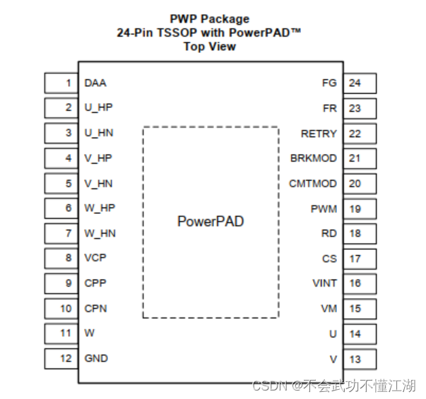
2. Pin Introduction
| name | describe |
|---|---|
| CPN | Charge pump switching node,Connect a 0.1-µF X7R capacitor rated for VM between CPN and CPP |
| CPP | Charge pump switching node,Connect a 0.1-µF X7R capacitor rated for VM between CPN and CPP |
| VCP | Charge pump output,Connect a 16-V, 1-µF ceramic capacitor to VM |
| GND | Device ground,Must be connected to board ground |
| VINT | Integrated regulator output,Integrated regulator (typical voltage 5 V) mainly for internal circuits; Provide external power for less than 20 mA. Bypass to GND with a 10-V, 2.2-µF ceramic capacitor |
| VM | Power supply |
| CS | Current limit setting pin |
| DAA | Drive angle adjustment configuration pin,Low: 10° drive angle adjustment,High: 5° drive angle adjustment,Floating: adaptive drive angle adjustment |
| FG | Frequency indication pin,Open drain Electrical Frequency Output pin. One toggle per electrical cycle. Requires an external pull-up of 3.3-kΩ. |
| FR | Motor direction control,Direction Control Input.When low, phase driving sequence is U → V → W ( U phase is leading V phase by 120°).When high, the phase driving sequence is U → W → V. |
| BRKMOD | Brake mode setting,Low: Coasting mode (phases are tri-stated),High: Brake mode (phases are driven low) |
| PWM | Variable duty cycle PWM input for speed control |
| RD | Lock indication pin |
| RETRY | Auto retry timing configure |
| CMTMOD | Commutation mode setting,Low: Sinusoidal operation mode with 0° Hall placement,High: Sinusoidal operation mode with 30° Hall placement,Floating: Trapezoidal operation mode with 30° Hall placement |
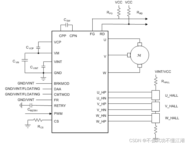
We only need to pay special attention to a few of the above pins , Including pulse width modulation (PWM) Input ( Speed command )、FG Output ( Speed feedback )、FR Input ( Forward and reverse control ) as well as RD Output ( Motor lock indication ).
FG and RD yes DRV10970 Feedback to MCU The signal of
CMTMOD Is the setting mode , Generally will CMTMOD Setting low level is sinusoidal mode 0° Place hall element ,
BRKMOD Is the braking mode setting , take BRKMOD The pin is set to low level , Even if BRKMOD The motor set to high level will not brake , Because this pin is used to set the braking mode , Instead of directly braking the motor , Only power off or will PWM Set to 0 Before you can brake .
DAA Is the angle setting of the drive motor , Set it to float , Floating is the adaptive angle to drive the motor
PWM It's the connection MCU Of PWM Output pins ,PWM The frequency of is 15Khz-100Khz.
Two 、 Use steps
1. Program
So it's using DRV10970 when , We need to PWM,FR,BM,CM,DAA Just set it up , I use two chips here to drive two motors
void PWM_Configuration(u16 arr,u16 pre)
{

	GPIO_InitTypeDef GPIO_InitStructure;
	TIM_TimeBaseInitTypeDef	TIM_TimeBaseStructure;
	TIM_OCInitTypeDef TIM_OCInitStructure;
// TIM_BDTRInitTypeDef TIM_BDTRInitStructure;

	RCC_AHB1PeriphClockCmd( RCC_AHB1Periph_GPIOA | RCC_AHB1Periph_GPIOB | RCC_AHB1Periph_GPIOC |RCC_AHB1Periph_GPIOD, ENABLE);
  RCC_APB1PeriphClockCmd(RCC_APB1Periph_TIM12, ENABLE);

	GPIO_PinAFConfig(GPIOB,GPIO_PinSource14,GPIO_AF_TIM12); //PB14  Reuse  TIM12
	GPIO_PinAFConfig(GPIOB,GPIO_PinSource15,GPIO_AF_TIM12); //PB14  Reuse  TIM12

	// PWM
	GPIO_InitStructure.GPIO_Pin =  GPIO_Pin_14 | GPIO_Pin_15;		 //
	GPIO_InitStructure.GPIO_Speed = GPIO_Speed_100MHz;
  GPIO_InitStructure.GPIO_Mode = GPIO_Mode_AF;
	GPIO_InitStructure.GPIO_OType = GPIO_OType_PP; // Multiplexing push pull output
	GPIO_InitStructure.GPIO_PuPd = GPIO_PuPd_UP; // Pull up
	GPIO_Init(GPIOB,&GPIO_InitStructure); // initialization  PB14

	//M1
	//GPIO DAA  In the air  M2 PD14--DAA
	GPIO_InitStructure.GPIO_Pin =  GPIO_Pin_8 | GPIO_Pin_14 ;
	GPIO_InitStructure.GPIO_Mode = GPIO_Mode_IN;// Normal input mode
	GPIO_InitStructure.GPIO_OType = GPIO_OType_PP;//
	GPIO_InitStructure.GPIO_Speed = GPIO_Speed_100MHz;//100MHz
	GPIO_InitStructure.GPIO_PuPd = GPIO_PuPd_NOPULL;// Floating space
	GPIO_Init(GPIOD, &GPIO_InitStructure);// initialization GPIOD

	GPIO_InitStructure.GPIO_Pin = GPIO_Pin_8 ;	 //GPIO_Pin_11
	GPIO_InitStructure.GPIO_Mode = GPIO_Mode_OUT;// Normal output mode
	GPIO_InitStructure.GPIO_OType = GPIO_OType_PP;// Push pull output
	GPIO_InitStructure.GPIO_Speed = GPIO_Speed_100MHz;//100MHz
	GPIO_InitStructure.GPIO_PuPd = GPIO_PuPd_UP;// Pull up
	GPIO_Init(GPIOB, &GPIO_InitStructure);// initialization GPIOD

			//GPIO M1--PD12--CM
	GPIO_InitStructure.GPIO_Pin = GPIO_Pin_12 | GPIO_Pin_15 ;	 //M2 PD15--FR
	GPIO_InitStructure.GPIO_Mode = GPIO_Mode_OUT;// Normal output mode
	GPIO_InitStructure.GPIO_OType = GPIO_OType_PP;// Push pull output
	GPIO_InitStructure.GPIO_Speed = GPIO_Speed_100MHz;//100MHz
	GPIO_InitStructure.GPIO_PuPd = GPIO_PuPd_UP;// Pull up
	GPIO_Init(GPIOD, &GPIO_InitStructure);// initialization GPIOD

				//GPIO M2--PA12--CM M2-PA11-BM
	GPIO_InitStructure.GPIO_Pin = GPIO_Pin_11 | GPIO_Pin_12 ;
	GPIO_InitStructure.GPIO_Mode = GPIO_Mode_OUT;// Normal output mode
	GPIO_InitStructure.GPIO_OType = GPIO_OType_PP;// Push pull output
	GPIO_InitStructure.GPIO_Speed = GPIO_Speed_100MHz;//100MHz
	GPIO_InitStructure.GPIO_PuPd = GPIO_PuPd_UP;// Pull up
	GPIO_Init(GPIOA, &GPIO_InitStructure);// initialization GPIOD

	//GPIO //FG and RD all feedback
	GPIO_InitStructure.GPIO_Pin =  GPIO_Pin_9|  GPIO_Pin_13;	// Input
	GPIO_InitStructure.GPIO_Mode = GPIO_Mode_IN;// Normal input mode
	GPIO_InitStructure.GPIO_Speed = GPIO_Speed_100MHz;//100MHz
	GPIO_InitStructure.GPIO_PuPd = GPIO_PuPd_UP;//
	GPIO_Init(GPIOD, &GPIO_InitStructure);// initialization GPIOD

		//GPIO // M2--PC8--RD M2--FG--PC14
	GPIO_InitStructure.GPIO_Pin = GPIO_Pin_8 | GPIO_Pin_14;	// Input
	GPIO_InitStructure.GPIO_Mode = GPIO_Mode_IN;// Normal input mode
	GPIO_InitStructure.GPIO_Speed = GPIO_Speed_100MHz;//100MHz
	GPIO_InitStructure.GPIO_PuPd = GPIO_PuPd_UP;//
	GPIO_Init(GPIOC, &GPIO_InitStructure);// initialization GPIOD

	//GPIO // CMTMOD--PD10
	GPIO_InitStructure.GPIO_Pin =  GPIO_Pin_10|GPIO_Pin_11;	// Input
	GPIO_InitStructure.GPIO_Mode = GPIO_Mode_OUT;// Normal input mode
	GPIO_InitStructure.GPIO_Speed = GPIO_Speed_100MHz;//100MHz
	GPIO_InitStructure.GPIO_PuPd = GPIO_PuPd_DOWN;//
	GPIO_Init(GPIOD, &GPIO_InitStructure);// initialization GPIOD


	TIM_TimeBaseStructure.TIM_Period= arr-1;
	TIM_TimeBaseStructure.TIM_Prescaler= pre-1;
	TIM_TimeBaseStructure.TIM_CounterMode=TIM_CounterMode_Up;
	TIM_TimeBaseStructure.TIM_ClockDivision=TIM_CKD_DIV1;
	TIM_TimeBaseInit(TIM12,&TIM_TimeBaseStructure);	 //TIM12

	TIM_OCInitStructure.TIM_OCMode = TIM_OCMode_PWM1;
	TIM_OCInitStructure.TIM_OutputState = TIM_OutputState_Enable;
	TIM_OCInitStructure.TIM_OCPolarity = TIM_OCPolarity_High;

// TIM_DeInit(TIM12);

	TIM_OC1Init(TIM12, &TIM_OCInitStructure);// Initialize peripherals TIM1 OC1--OC4
	TIM_OC2Init(TIM12, &TIM_OCInitStructure);
	TIM_OC3Init(TIM12, &TIM_OCInitStructure);
	TIM_OC4Init(TIM12, &TIM_OCInitStructure);

	TIM_OC1PreloadConfig(TIM12, TIM_OCPreload_Enable);// Enable preload register
	TIM_OC2PreloadConfig(TIM12, TIM_OCPreload_Enable);
  TIM_OC3PreloadConfig(TIM12, TIM_OCPreload_Enable);
	TIM_OC4PreloadConfig(TIM12, TIM_OCPreload_Enable);

	TIM_ARRPreloadConfig(TIM12,ENABLE);

	TIM_Cmd(TIM12, ENABLE);

	//M1
	// PD12--CM
	GPIO_ResetBits(GPIOD, GPIO_Pin_10 );//PD10---FR PD11---BM

	GPIO_SetBits(GPIOD, GPIO_Pin_12 );// PD12--CM

	//M2
	GPIO_ResetBits(GPIOA, GPIO_Pin_11 );// PA11--BM
	GPIO_SetBits(GPIOA, GPIO_Pin_12 );// PD12--CM

}
3、 ... and . How to judge when the chip is damaged
When VM for 12V When electricity is on , If VINT No, 5V Output , It can be considered that the chip is broken
边栏推荐
- Show strength. In this way, the mobile phone will not be difficult to move forward
- [learning notes] connectivity and circuit of graph
- The function of qualifier in C language
- Opengauss database source code analysis series articles -- detailed explanation of dense equivalent query technology (Part 2)
- SaaS multi tenant solution for FMCG industry to build digital marketing competitiveness of the whole industry chain
- World Environment Day | Chow Tai Fook serves wholeheartedly to promote carbon reduction and environmental protection
- ASP.NET大型外卖订餐系统源码 (PC版+手机版+商户版)
- mysql8.0JSON_ Instructions for using contains
- R Language ggplot2 Visualization: visualize linegraph, using Legend in Theme function. Paramètre de position emplacement de la légende personnalisée
- 循环不变式
猜你喜欢
Loop invariant
Why do mechanical engineers I know complain about low wages?

Qingda KeYue rushes to the science and Innovation Board: the annual revenue is 200million, and it is proposed to raise 750million

Thymeleaf th:classappend attribute append th:styleappend style append th:data- custom attribute
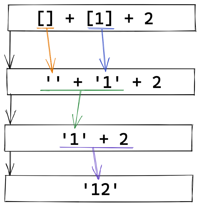
分享 20 个稀奇古怪的 JS 表达式,看看你能答对多少
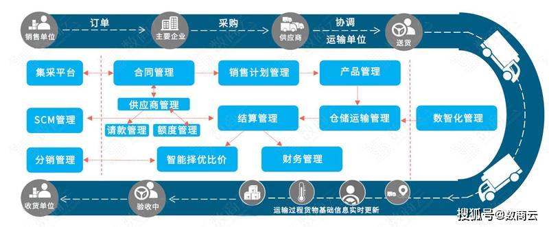
乌卡时代下,企业供应链管理体系的应对策略
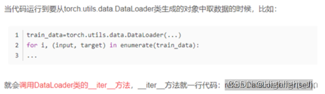
浅谈Dataset和Dataloader在加载数据时如何调用到__getitem__()函数
申请代码签名证书时如何选择合适的证书品牌?
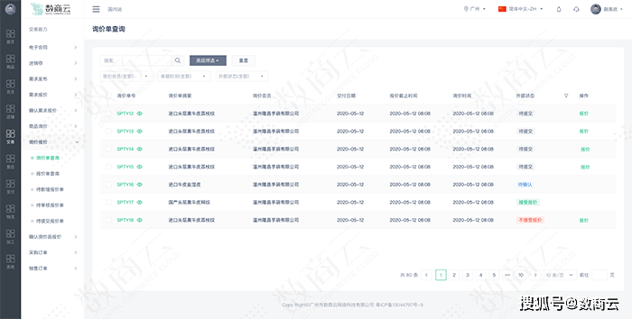
Online electronic component purchasing Mall: break the problem of information asymmetry in the purchasing process, and enable enterprises to effectively coordinate management
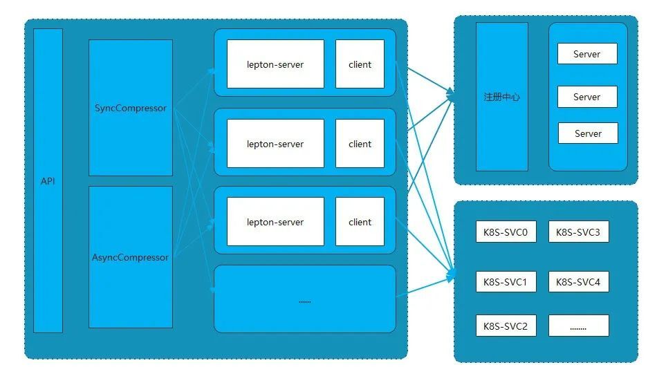
Lepton 无损压缩原理及性能分析
随机推荐
ASP.NET大型外卖订餐系统源码 (PC版+手机版+商户版)
The speed monitoring chip based on Bernoulli principle can be used for natural gas pipeline leakage detection
如何将电脑复制的内容粘贴进MobaXterm?如何复制粘贴
js亮瞎你眼的日期选择器
01. Solr7.3.1 deployment and configuration of jetty under win10 platform
Is it OK to open the securities account on the excavation finance? Is it safe?
Mysql database installation tutorial under Linux
Security analysis of Web Architecture
循环不变式
freesurfer运行完recon-all怎么快速查看有没有报错?——核心命令tail重定向
Penetration testing methodology
选择排序和冒泡排序
【学习笔记】图的连通性与回路
R language dplyr package select function, group_ By function, mutate function and cumsum function calculate the cumulative value of the specified numerical variable in the dataframe grouping data and
How to deeply understand the design idea of "finite state machine"?
无密码身份验证如何保障用户隐私安全?
How can non-technical departments participate in Devops?
R language ggplot2 visual bar graph: visualize the bar graph through the two-color gradient color theme, and add label text for each bar (geom_text function)
How to make a second clip of our media video without infringement
Discussion on memset assignment