当前位置:网站首页>VirtualLab basic experiment tutorial -6 Blazed grating
VirtualLab basic experiment tutorial -6 Blazed grating
2022-06-12 18:08:00 【Chengyuan】
List of articles
Preface
This is the fifth collective work of Dachuang team , Basic experiments for physical optics – Poisson bright spot made exploration and attempt .
One 、 Principle of blazed grating
1、 Review multi slit Fraunhofer diffraction
The multi slit diffraction with spatially modulated amplitude is the result of single slit diffraction and multi slit interference .
I ( P ) = I 0 ( s i n α α ) 2 ( s i n N δ 2 s i n δ 2 ) 2 I(P)=I_0(\frac{sin\alpha}{\alpha})^2(\frac{sin\frac{N\delta}{2}}{sin\frac{\delta}{2}})^2 I(P)=I0(αsinα)2(sin2δsin2Nδ)2
Single slit diffraction factor : ( s i n α α ) 2 (\frac{sin\alpha}{\alpha})^2 (αsinα)2, among α = π λ a s i n θ \alpha=\frac{\pi}{\lambda}asin\theta α=λπasinθ
It can be seen that when the diffraction is great , θ = 0 \theta=0 θ=0
Multi slit interference factor : ( s i n N δ 2 s i n δ 2 ) 2 (\frac{sin\frac{N\delta}{2}}{sin\frac{\delta}{2}})^2 (sin2δsin2Nδ)2, among δ = 2 π λ d s i n θ \delta=\frac{2\pi}{\lambda}dsin\theta δ=λ2πdsinθ
It can be seen that the zero order interference principal maximum , θ = 0 \theta=0 θ=0
in other words , At this time, the central maximum of single slit diffraction coincides with the zero order principal maximum of inter slit interference . But amplitude grating is used as dispersion element , The zero order spectrum of colorless dispersion occupies a large part of the total energy , The higher spectral energy used in spectral analysis is very small , Therefore, the diffraction efficiency is extremely low .
2、 Blazed grating
therefore , Try to separate the principal maxima of single slit diffraction from the zero order principal maxima of multi slit interference , Make it no longer coincide . From the above formula we can see that , If the angle corresponding to the principal maximum of single slit diffraction is not the same as that corresponding to the zero order principal maximum of multi slit interference , At this time, the principal maxima of single slit diffraction is separated from the zero order principal maxima of multi slit interference .
The cleverness of blazed grating lies in that the groove surface is not parallel to the grating surface , There is an included angle γ \gamma γ, It is called the shining angle .
The main maximum direction of the grating interference is the zero order direction of the normal direction of the grating surface , The central direction of the maximum diffraction is determined by the normal direction of the groove surface .
When the ray is at an angle with the normal of the grating surface i i i The incident , The reflection angle is θ \theta θ, Then the principal maxima of interference between grooved surfaces are determined by the grating equation , namely d ( s i n i + s i n θ ) = m λ d(sini+sin\theta)=m\lambda d(sini+sinθ)=mλ
Because the central direction of the maximum diffraction is from the normal direction of the groove surface , And the angle between the groove surface and the grating surface γ \gamma γ, Therefore, the central maximum of the diffraction of a single grooved surface interferes with m When the level main maximum coincides , i = θ = γ i=\theta=\gamma i=θ=γ
2 d s i n γ = m λ 2dsin\gamma=m\lambda 2dsinγ=mλ
When m = 1 m=1 m=1, Incident wavelength is λ B \lambda_B λB,
2 d s i n γ = λ B 2dsin\gamma=\lambda_B 2dsinγ=λB
namely : The wavelength is λ B \lambda_B λB Of 1 Level spectrum to obtain the sparkle , And get the maximum light intensity .
obviously , Blazed grating only produces extremely large light intensity for the blazed wavelength in the same level of spectrum , However, there is a certain width in the center of the diffraction of the grooved surface , therefore , The spectral lines within a certain wavelength range near the blazed wavelength also have considerable light intensity , Therefore, blazed grating can be used in a certain wavelength range .
Two 、Virtualab Simulation
1、 Build a light path
This experiment is different from the previous experiment , To open the light path template, you need to open the raster toolbox in the window above the software :
stay Gratings Medium 2D Select the serrated grating, namely the blazed grating 
Click to open a light path with components already built , We just need to adjust the data we need :
Set the relevant parameters of the raster , Double click to open the raster :
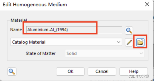
First, set the material of the grating base , stay Base Block Open in Edit:
because Al We choose it as the material of grating , Open the material library to search Al.
The basic parameters of the material can be obtained ,( It can also be found in additional information See other parameters of the material )
Set the thickness between the base and the stack 0.
Then set the stack , We are using the first surface stack , stay Stacks Click on the Edit modify :
After entering, you can observe the schematic diagram of the saw tooth of the grating , Click on the small pencil pattern to enter the edit 
Below 1 Set the grating period at ,2 Set the modulation depth at , This experiment is set as 10um, That is, the flare angle is 45 degree , Thereafter 3 Set the height at the following position x Decline , Offset and rotation angle are not set .
The raster size is set to 2mm×2mm.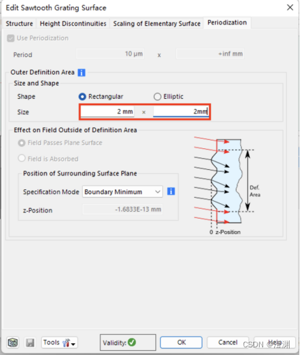
Then set the algorithm , Choose Fourier modal method , Click on Edit Enter editor .
By calculation , When the wave level is 138 The effect is better .
In the structural decomposition, change the precision to 2, The precision here corresponds to the number of serrations ( The higher the precision, the smoother the serrated grating )
You can click on the bottom right preview See the decomposition diagram in .
There are two ways for light to irradiate the grating, that is, the vertical groove surface or the grating surface , We choose the common vertical slot plane for incidence :
stay position Medium basal positioning Rotate the raster 45 degree , You can choose to rotate around the axis Y Shaft rotation ( Upper figure ), You can also choose to set... In the Cartesian coordinate system ( The figure below )

Because of the grating period and modulation depth 10um Set up , We can calculate by formula 10 The wavelength of the first stage blaze is 1.4142um.
Set the propagation space to... In the light path editor interface Al.
2、 Analyzer settings
After that, the grating level analyzer is modified .
Blazed grating mainly considers reflection , So uncheck the transmission .
Then select single level output and polarization .
Only when single level output is checked will the... Above appear Single Analyzer.
The modification level is -10,Y Direction is 0
Finally, the simulation engine selects the raster level analyzer .
Then we get the result graph .
3、 ... and 、7.6.1.18 The operation difference of version
When choosing Fourier modal method , Click on Edit Enter editor
By calculation , When the wave level is 138 The effect is better ,Edit When selected, set the evanescent wave level to... In the pop-up box 138 Time .
Propagation Medium Advanced Settings Set the precision of structural decomposition :
In the structural decomposition, change the precision to 2, The precision here corresponds to the number of serrations ( The higher the precision, the smoother the serrated grating )
Four 、 Result display
Next , We use Parameter run Change parameters for simulation .
1、 Change the wavelength

First , Change the wavelength from 1.21um Change to 1.61um, take 21 Step , After operation , You can get the following two images .

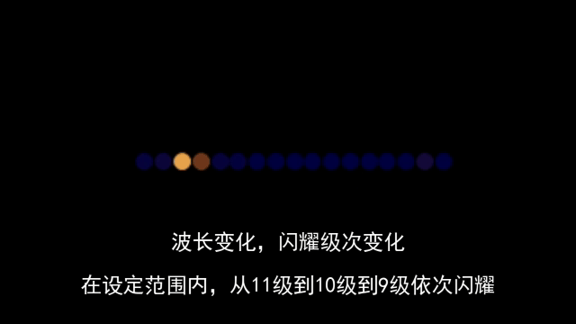
If the blaze wavelength is not reached , It will lead to the dispersion of energy , Make nearby levels shine .
Click on the probe .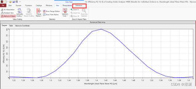
Click to see 10 The maximum value near level .
2、 Change the raster angle
next , Change the angle from -60° Change to -30°, Also take 21 Step , The following curve can be obtained .

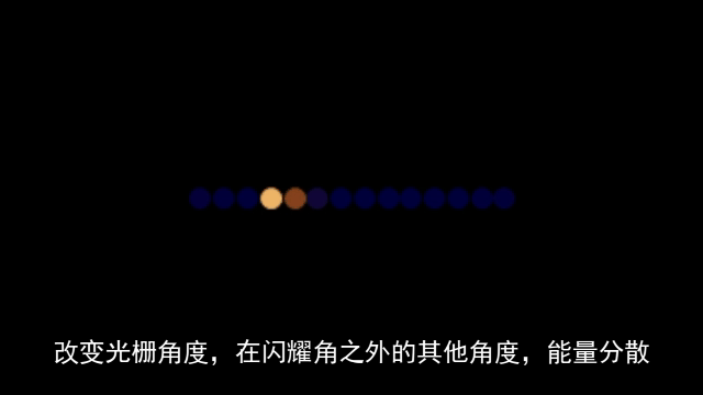
similarly , If the flare angle is not reached , It will lead to the dispersion of energy , Make nearby levels shine .
Click to view the maximum value , give the result as follows .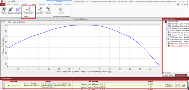
3、 Change both parameters at the same time
stay parameter run Check both angle and wavelength , That is, change the values of the two parameters at the same time , Also take 21 Step , Change the mode to Scanning.
Change to... In settings 2D Pattern , choice Interpolated View, Smooth the image , And set the color to Rainbow.

You can get the color pattern as shown in the figure below .

Click to view the maximum value , You can get the following results .
Back again parameter run The interface of .
After modifying the settings, view the current one-dimensional multi graph pattern .
Click on Multigraph Mode, Select the third interpolation method ,Method of Object.
Click to open the line chart settings , take Symbol All changed to No Symbol.
The relationship curve between wavelength and angle shown in the figure below can be obtained .
summary
This article is written by members of Da Chuang team : Tang Yiheng 、 Help Yang Yu 、 Huang Yinuo 、 Li Sitong 、 Ming Yue jointly completed .
There are many details about blazed grating , it is to be noted that .
This article adopts the trial version and 7.6.1.18 Version for experiment and demonstration , Enhanced applicability .
attach
I wish all the students of the college entrance examination can shine on their own grades .
边栏推荐
- 联想回应笔记本太多太杂乱:现在是产品调整期 未来将分为数字/Air/ Pro三大系列
- leetcode 674 最长递增子串
- 低代码平台调研结果
- A story on the cloud of the Centennial Olympic Games belonging to Alibaba cloud video cloud
- C brief introduction
- js判断回文数
- JS中的栈(含leetcode例题)<持续更新~>
- 重构--梳理并分解继承体系
- Byte flybook Human Resources Kit three sides
- Make good use of IDE, speed up R & D efficiency by 100%
猜你喜欢

ESP32-C3 ESP-IDF 配置smartconfig 和 sntp 获取网络时间

vant3+ts 封装uploader上传图片组件

Variable of C #

js两数之和

Window版本pytorch入门深度学习环境安装与配置

Make good use of IDE, speed up R & D efficiency by 100%

Vant3+ts dropdownmenu drop-down menu, multi data can be scrolled

Nixos 22.05 installation process record

C brief introduction

Introduction to reinforcement learning and analysis of classic items 1.3
随机推荐
EasyCode模板
Tutoriel de démarrage rapide JDBC
联想回应笔记本太多太杂乱:现在是产品调整期 未来将分为数字/Air/ Pro三大系列
Lambda - 1
ESP-IDF 添加自己的组件
ES7 does not use parent-child and nested relationships to implement one to many functions
Stream flow precautions
[csp]202012-2 optimal threshold for period end forecast
Typescript type declaration file (III)
Message queuing MySQL tables that store message data
leetcode 674 最长递增子串
Queue priority of message queue practice
JS sum of two numbers
Bug record: data truncation: incorrect datetime value:
Esp-idf adds its own components
USB转串口那些事儿—最大峰值串口波特率VS连续通信最高波特率
Eve-ng installation (network device simulator)
Office application cannot start normally 0xc0000142
PHP implementation of infinite classification tree (recursion and Optimization)
VirtualLab基础实验教程-6.闪耀光栅