当前位置:网站首页>Proteus Software beginner notes
Proteus Software beginner notes
2022-06-29 12:41:00 【Blog ABCD hukang】
List of articles
- Proteus Software beginner
- One 、 Common components
- Two 、 Learning video
- 3、 ... and 、Project
- 1、 Crystal oscillator circuit and reset circuit
- 2、LED Realization of water lamp
- 3、 Nixie tube
- 4、 Key
- 5、 Timer
- 6、 interrupt
- 7、 Serial port communication
- 8、 simulation 89C51 Communication with upper computer
- 9、LCD1602 Application
- 10、 Lattice
- 11、DA Conversion principle and Realization of simple waveform generator
- 12、 External interrupt
- 13、 MCU serial port
Proteus Software beginner
One 、 Common components

Two 、 Learning video
Proteus Use the tutorial to view the video link , I think it's very good :https://www.bilibili.com/video/BV1Y7411N7YK?p=2
Keil5 combination Proteus You can take a look at this video :
https://www.bilibili.com/video/BV1H7411n7AY?p=4&spm_id_from=pageDriver

3、 ... and 、Project
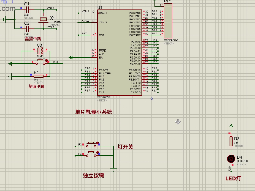
1、 Crystal oscillator circuit and reset circuit
Clock circuit
- chip :AYM89C51
- Crystal oscillator :CRY,12M
- capacitance :CAP,22pf
- effect : Crystal oscillator circuit provides clock signal for single chip microcomputer . The crystal oscillator circuit produces the clock frequency that must be used by the single chip microcomputer , All the instructions sent by the single chip microcomputer are based on this
- The higher the clock frequency of the crystal oscillator , The faster the MCU runs . It is one by one from ROM Get the command from , Then go ahead and do it . The time that a single-chip computer accesses each time is called the machine cycle , The machine cycle is divided into 12 Clock cycles
Reset circuit : Power on reset , Key reset
- resistance :RES
- effect : Use it to restore the circuit to its original state , Like the reset button of the calculator , In order to return to the original state , Recalculate .

2、LED Realization of water lamp
2.1、LED principle
LED, Tape selection ACTIVE Of , You can see the visualization of components , Is it on or off
Direction of current :P ----> N
If it's Silicon ,0.7V, If it is germanium ,0.3V

2.2、 Anode connection and cathode connection
Supply anode connection method : Will all LED Of P The poles are connected together , here N It is very necessary to connect to low level , Low level light , High level off , Low level active
Supply cathode connection method : Will all LED Of N The poles are connected together , here P It is necessary to connect high level , High active
The current that the single chip computer can draw is 20mA, Therefore, the anode connection method needs resistance ( The resistance value shall not be less than 250) Can be connected to the single chip computer

2.3、 Breathing lamp to achieve flashing code
#include"reg51.h"
// sbit  Means to control the position
sbit LED0 = P2^0;
/* *  The time delay function  *  The time delay function `delay()` The essence of : Use empty statements to occupy program time , So as to achieve the effect of delay  */
void delay(unsigned int n)
{

	unsigned int i=0,j=0;
	for(i=0;i<n;i++)
	{

		for(j=0;j<120;j++);
	}
}

void main()
{

	while(1)
	{

		LED0 = 0;// bright
		delay(5);// Add delay function
		LED0 = 1;// destroy
		delay(5);// Add delay function
	}
}
2.4、 Breathing lamp implementation code ( Anode and cathode connection )
#include"reg51.h"
// sbit  Means to control the position
sbit LED0 = P2^0;
/* *  The time delay function  */
void delay(unsigned int n)
{

	unsigned int i=0,j=0;
	for(i=0;i<n;i++)
	{

		for(j=0;j<120;j++);
	}
}

/* *  Realize the effect of running water lamp  */
void led()
{

	int i=0;
	for(i=0;i<8;i++)
	{

		/* *  Because the low level is on , So reverse operation , *  Because the running water lamp operation is realized , So the shift operation  * P2  For anode connection  * P1  For cathode connection  */
		P2=~(0x01<<i);//~0000 0001 ->0000 0010 -> 0000 0100
		P1=(0x01<<i);//~0000 0001 ->0000 0010 -> 0000 0100
		delay(50);
	}
}

void main()
{

	while(1)
	{

		led();
	}
}
2.5、 Operation of general flow lamp
The output data is represented by an array , use for Loop through it
The code is as follows :
#include"reg51.h"
//  Take turns scrolling the little light data
unsigned char leddat[]={
    0x01,0x02,0x04,0x08,0x10,0x20,0x40,0x80};

void delay(unsigned int n)
{

	unsigned int i=0,j=0;
	for(i=0;i<n;i++)
	{

		for(j=0;j<120;j++);
	}
}

void led()
{

	int i=0;
	for(i=0;i<8;i++)
	{

		P2=~leddat[i];
		delay(100);
	}
}

void main()
{

	//  Ensure that the program can run continuously
	while(1)
	{

		led();
	}
}
2.6、 Realize the effect of fancy running water lamp
#include"reg51.h"
unsigned char leddat[50]={

0x01,0x02,0x04,0x08,0x10,0x20,0x40,0x80,0x81,0x82,
0x84,0x88,0x90,0xA0,0xC0,0xC1,0xC2,0xC4,0xC8,0xD0,
0xE0,0xE1,0xE2,0xE4,0xE8,0xF0,0xF1,0xF2,0xF4,0xF8,
0xF9,0xFA,0xFC,0xFD,0xFE,0xFF,0xFF,0x00,0xFF,0x00
};

/* Delay function  */
void delay(unsigned int n)
{

	unsigned int i=0,j=0;
	for(i=0;i<n;i++)
	{

		for(j=0;j<120;j++);
	}
}

void led()
{

	int i=0;
	for(i=0;i<50;i++)
	{

		P2 = ~leddat[i];
		delay(100);
	}
}

void main()
{

	while(1)
	{

		led();
	}
}
3、 Nixie tube
3.1、 The structure and principle of digital tube

3.2、 Letters and numbers are displayed on the nixie tube

- dp: Is the decimal point position

3.3、LED Static display and dynamic display of digital tube
1、 Static display mode

2、 characteristic
- The common end is directly grounded ( Supply cathode ) Or connect the power supply ( Supply anode )
- Line selection of each digital segment and a group of I/O The interface line is connected
- Each nixie tube always shows
3、 Realization effect : from 0–9 A circuit diagram that changes repeatedly
Take cathode connection as an example 
4、 Code
#include"reg51.h"
unsigned char s[]={
    0x3F,0x06,0x5B,0x4F,0x66,0x6D,0x7D,0x07,0x7F,0x6F};//  Supplying Yin 0--9


/* *  Delay function  */
void delay(unsigned int n)
{

	unsigned int i=0,j=0;
	for(i=0;i<n;i++)
	{

		for(j=0;j<120;j++);
	}
}

/* *  Show function  */
void seg()
{

	//P2 = 0x3F;//0011 1111
	int i =0;
	for(i=0;i<10;i++)
	{

		P2 = s[i];
		delay(300);
	}
}

void main()
{

	while(1)
	{

		seg();
	}
}
Be careful : The anode connection method is the same as above , What needs to be replaced is the digital tube , Connection and negation in code
3.4、LED The dynamic display of digital tube
1、 principle

- characteristic
- From bottom to top is :a,b,c,d,e,f,g,db
- Segment line selection of all nixie tubes and one group I/O Interface lines are connected together
- The common end of each nixie tube consists of one I/O Line control
- Display as one by one
2、 Realization effect

3、 Code
#include"reg51.h"
unsigned char s[]={
    0x3F,0x06,0x5B,0x4F,0x66,0x6D,0x7D,0x07,0x7F,0x6F};//  Supplying Yin 0--9
unsigned char str[]={
    0x76,0x79,0x38,0x38,0x3F};// HELLO
unsigned char wei[]={
    0x00,0x01,0x02,0x03,0x04,0x05,0x06,0x07};// Display different bits
//  If the display 1-8 It is directly connected with the single chip microcomputer 10-17 Connect , Display different bits using the following
// unsigned char wei[]={0x01,0x02,0x04,0x08,0x10,0x20,0x40,0x80};


/* *  Delay function  */
void delay(unsigned int n)
{

	unsigned int i=0,j=0;
	for(i=0;i<n;i++)
	{

		for(j=0;j<120;j++);
	}
}

/* *  Show function  */
void seg()
{

	//P2 = 0x3F;//0011 1111
	int i =0;
	for(i=0;i<5;i++)
	{

		P3=wei[i];
		P2 = str[i];//0011 1111
		delay(5);
	}
}

void main()
{

	while(1)
	{

		seg();
	}
}
4、 Key
4.1、 The basic principle of keyboard

4.2、 Elimination of jitter
The jitter is about 10ms~20ms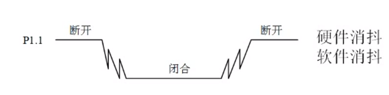

4.3、 Keyboard classification


4.4、 Matrix keyboard key position recognition

4.5、 Realization effect

Code
#include"reg51.h"
sbit key0=P1^0;
unsigned char s[]={
    0x3F,0x06,0x5B,0x4F,0x66,0x6D,0x7D,0x07,0x7F,0x6F};//  Supplying Yin 0--9
unsigned char num=0,flag=0;

void delay(unsigned int n)
{

	unsigned int i=0,j=0;
	for(i=0;i<n;i++)
	{

		for(j=0;j<120;j++);
	}
}
//  Key operation
void key()
{

// if(key0==0)
// {

// num++;
// }
		if(key0==0&&flag==0)
	{

		flag=1;
	}
	if(flag==1&&key0==1)
	{

		num++;
		flag=0;
	}
}

//  Nixie tube operation , Use flag bits to eliminate jitter
void seg()
{

	P2=s[num];
	if(num==10)
	{

		num=0;
	}

}

void main()
{

	while(1)
	{

		key();
		seg();
	}

}
5、 Timer
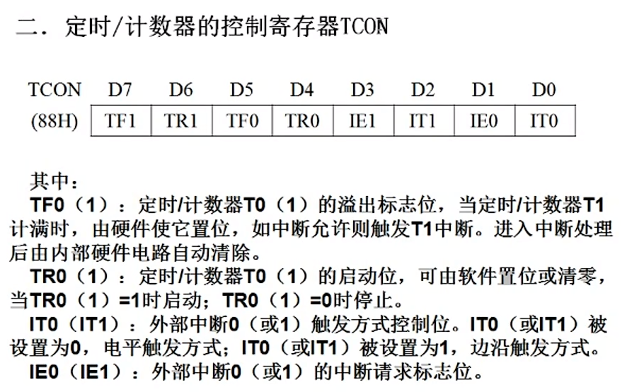
5.1、 timing / Counter mode and control register


6、 interrupt
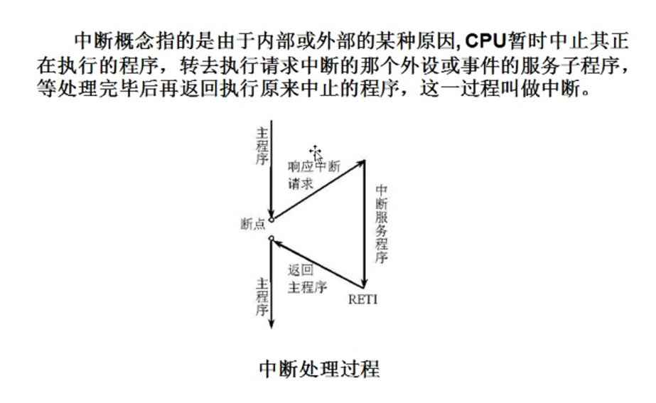
6.1、 Interrupt profile
6.2、 Interrupt allow control
Mark with T The expression of is related to the timer 
6.3、 Priority control


6.4、 Entry number of each interrupt service program

6.5、 External interrupt
External interrupt , Low level , Falling edge trigger .
6.6、 Circuit diagram

6.7、 Code
Realize anti shake operation , Press the keyboard num Value plus one
#include"reg51.h"
sbit ex=P3^2;
unsigned char s[]={
    0x3F,0x06,0x5B,0x4F,0x66,0x7D,0x07,0x7F,0x6F};// Supply cathode 0-9
unsigned char num=0;

void initex()
{

	IT0=1;// Set the edge trigger
	EX0=1;// Open external interrupt
	EA=1;// Carry out enabling , Open total interrupt
	ex=1; Set to falling edge

}
void display()
{

	P2=s[num];
	if(num===10)
	{

		num=0;
	}
}

void main()
{

	initex();
	while(1)
	{

		display();
	}
}
7、 Serial port communication
The following are 0 Is acceptable ,1 Indicates that the reception is complete

7.1、 Serial port Control register SCON
Control the communication mode of serial port , The difference between serial ports is the baud rate , In general 1 It's used a lot


7.2、 Power control register PCON

7.3、 The way 1 How it works


8、 simulation 89C51 Communication with upper computer
8.1、 Circuit diagram

8.2、 Code
#include"reg51.h"
unsigned char recdat=0,flag=0;

void initscon()
{

	//  Serial port control register
	SCON=0x50;// 0101 0000
	//  Configure baud rate , By timer T1 produce , Parameter is :( yes 1 no 0 Related to external interrupts , Select timer 0 Or a counter 1 The pattern of , Pattern 0-13 position ,01-16 position ,10-8 position )
	TMOD=0x20;// 0010 0000
	//  Configure the initial value
	TH1=256-3;
	TL1=256-3;
	ES=1;//  Serial interrupt
	EA=1;// Open total interrupt
	TR1=1;// Turn on timer 1

}

//  send data
void senddat()
{

	SBUF=recdat;
	while(!T1);
	T1=0;

}

void main()
{

	//  Initialize serial port
	initscon();
	while(1)
	{

		// send data , Send by interrupt
		// receive data , Receive the returned data
		if(flag==1)
		{

			senddat();
			flag=0;
		}
	}
}

//  Serial interrupt service function
// 0 It's an external interrupt ,1 It's a timer. 0 The interrupt ,2 It's an external interrupt 1,3 It's a timer interrupt 1,4 Serial port interrupt
void scon_isr() interrupt 4
{

	// SBUF Represent cache
	recdat=SBUF;
}
9、LCD1602 Application
9.1、LCD1602 summary
LCD1602 yes 2*16 Character LCD module 

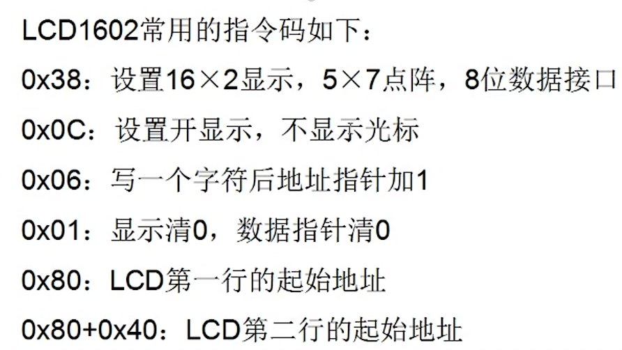
9.2、 Common script

9.3、 Read write sequence diagram


9.4、 Circuit diagram I
AT89C51 and LM016L
9.5、 Code 1
#include"reg51.h"
sbit RS=P3^0;
sbit RW=P3^1;
sbit E=P3^2;
unsigned char str[]={
    "count:"};
void delay(unsigned int n)
{

	unsigned int i=0,j=0;
	for(i=0;i<n;i++)
	{

		for(j=0;j<120;j++);
	}
}

void writedat(unsigned char dat)
{

	RS=1;
	RW=0;
	E=0;
	P2=dat;
	delay(5);
	E=1;
	E=0;
}


void writecom(unsigned char com)
{

	RS=0;
	RW=0;
	E=0;
	P2=com;
	delay(5);
	E=1;
	E=0;
}


void initlcd()
{

	//  Write command
	writecom(0x38);
	writecom(0x0c);
	writecom(0x06);
	writecom(0x01);

}


//  Show function
void display()
{

	unsigned int i=0;
	writecom(0x80);
	delay(5);
// writedat('A');
// delay(5);
// writedat('B');
// delay(5);
	while(str[i]!='\0')
	{

		writedat(str[i]);
		delay(5);
		i++;
	}
	writedat(0x36);
	delay(5);
}

void main()
{

	initlcd();
	while(1)
	{

		display();
	}
}
9.6、 Circuit diagram II
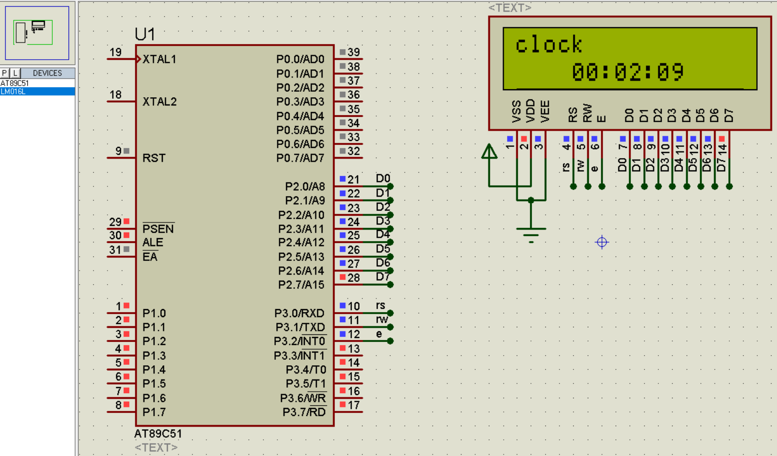
9.7、 Code 2
#include"reg51.h"
sbit RS=P3^0;
sbit RW=P3^1;
sbit E=P3^2;
unsigned char count=0;
unsigned int hour=0,min=0,sec=0;
unsigned char str1[]={
    "clock"};
//  Numbers are converted into characters with
unsigned char str[]={
    "0123456789"};

void delay(unsigned int n)
{

	unsigned int i=0,j=0;
	for(i=0;i<n;i++)
	{

		for(j=0;j<120;j++);
	}
}

void writedat(unsigned char dat)
{

	RS=1;
	RW=0;
	E=0;
	P2=dat;
	delay(5);
	E=1;
	E=0;
}


void writecom(unsigned char com)
{

	RS=0;
	RW=0;
	E=0;
	P2=com;
	delay(5);
	E=1;
	E=0;
}


void initlcd()
{

	//  Write command
	writecom(0x38);
	writecom(0x0c);
	writecom(0x06);
	writecom(0x01);

}


//  Show function
void display()
{

	unsigned char i=0;
	unsigned char temp0=0,temp1=0,temp2=0,temp3=0,temp4=0,temp5=0;
	temp0=hour/10;
	temp1=hour%10;
	temp2=min/10;
	temp3=min%10;
	temp4=sec/10;
	temp5=sec%10;
	writecom(0x80);
	delay(5);
	while(str1[i]!='\0')
	{

		writedat(str1[i]);
		delay(5);
		i++;
	}
	writecom(0x80+0x40+4);// Control the display in the middle
	writedat(str[temp0]);
	delay(5);
	writedat(str[temp1]);
	delay(5);
	writedat(':');
	delay(5);
	writedat(str[temp2]);
	delay(5);
	writedat(str[temp3]);
	delay(5);
	writedat(':');
	delay(5);
	writedat(str[temp4]);
	delay(5);
	writedat(str[temp5]);
	delay(5);
}
/* Timer */
void inittimer()
{

	TMOD=0x01;//  Select timer mode as 16 position
	TH0=(65536-50000)/256;//50ms
	TL0=(65536-50000)%256;
	ET0=1;// interrupt
	EA=1;// Turn on interrupt
	TR0=1;// Turn on timer 0
}


void main()
{

	initlcd();
	inittimer();
	while(1)
	{

		display();
	}
}

// Timer interrupt function
void timer0_isr() interrupt 1
{

	TH0=(65536-50000)/256;//50ms
	TL0=(65536-50000)%256;
	count++;
	if(count==20)//1s
	{

		sec=sec+1;
		count=0;
	}
	if(sec==60)
	{

		min=min+1;
		sec=0;
	}
	if(min==60)
	{

		hour=hour+1;
		min=0;
	}
	if(hour==24)
	{

		hour=0;
	}
}
9.8、 Realize electronic clock

10、 Lattice
10.1、 Circuit diagram
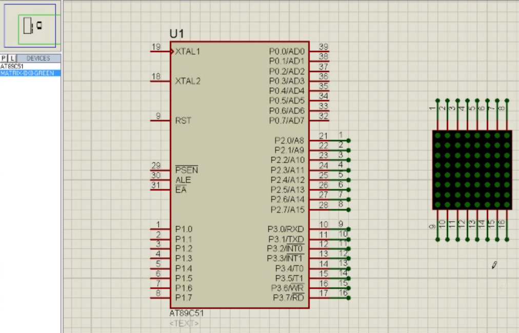

10.2、 Code
Realization 0

11、DA Conversion principle and Realization of simple waveform generator

12、 External interrupt
12.1、 Circuit diagram
12.2、 Code
The external interrupt implements the key : Add external interrupt , When you press the button , Trigger external interrupt , Low level , Little lights , Press again , The level value of the small lamp is reversed ( Or use the falling edge to trigger , When pressed, the light is on , The light goes out when lifting )
//  Variable definitions
uchar key_num; //  Key value
//  Function declaration
void Delay_function(uint x); // The time delay function
void Key_function(void); // Key function
void Monitor_function(void); //  Monitoring function
void Display_function(void); //  Show function
void Manage_function(void); //  Processing function
void Int0_Init(void); //  External interrupt 0 Initialization function
void Int1_Init(void); //  External interrupt 1 Initialization function
//  The main function
void main()
{

	Int0_Init(); // External interrupt 0 initialization
	Int1_Init(); // External interrupt 1 initialization
  	while(1)
	{

		Key_function(void);// Key function
		Monitor_function(void);//  Monitoring function
		Display_function(void);//  Show function
		Manage_function(void);//  Processing function
	}
}
// The time delay function
void Delay_function(uint x);
{

	uint m,n;
	for(m=x;m>0;m--)
	for(n=110;n>0;n--);
}
// Key function
void Key_function(void)


//  Monitoring function
void Monitor_function(void)
{


}
//  Show function
void Display_function(void)
{


}
//  Processing function
void Manage_function(void)
{


}
//  External interrupt 0 Initialization function
void Int0_Init(void)
{

	EA=1;//  Open total interrupt
	EX0=1;//  Allow external interrupts 0 Trigger interrupt
	IT0=1;//  Set the external interrupt trigger mode , The mode is triggered by the falling edge
}
//  External interrupt 1 Initialization function
void Int1_Init(void)
{

	EA=1;//  Open total interrupt
	EX0=1;//  Allow external interrupts 1 Trigger interrupt
	IT0=1;//  Set the external interrupt trigger mode , The mode is low level trigger
}
//  External interrupt 0 Interrupt service function
void Int0_IRQHandler(void) interrupt 0
{

	LED = ~LED;
}
//  External interrupt 01 Interrupt service function
void Int1_IRQHandler(void) interrupt 2
{

	LED = ~LED;
}
13、 MCU serial port
#include<reg51.h>// Go to the default path of the system to find the header file , It is not recommended to use#include"reg51.h"// First go to the user-defined path to find , Then go to the default path of the system to find , Recommended
The time delay function delay() The essence of : Use empty statements to occupy program time , So as to achieve the effect of delay
边栏推荐
- MySQL master-slave synchronous asynchronous replication semi synchronous replication full synchronous replication
- 爱可可AI前沿推介(6.29)
- Proteus软件初学笔记
- AGCO AI frontier promotion (6.29)
- nvtmpp
- Syntax of gbase8s database incompatible with for update clause
- Recommended model reproduction (II): fine arrangement model deepfm, DIN
- Unexpected ‘debugger‘ statement no-debugger
- Go learning - build a development environment vscode development environment golang
- Recommended model recurrence (I): familiar with torch rechub framework and use
猜你喜欢

How can colleges and universities build future oriented smart campus based on cloud native? Full stack cloud native architecture vs traditional IT architecture

How to create new user for ORACLE 19c (CDB & PDB)

Earth observation satellite data

How to install oracle19c in Centos8

1. Opencv实现简单颜色识别

一种可解释的几何深度学习模型,用于基于结构的蛋白质结合位点预测
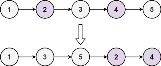
LeetCode_双指针_中等_328.奇偶链表

Bison uses error loop records

The blackened honeysnow ice city wants to grasp the hearts of consumers by marketing?
如何計算win/tai/loss in paired t-test
随机推荐
Earth observation satellite data
MySQL 主从复制原理以及流程
Gbase8s database select has a having clause
Recommended model recurrence (I): familiar with torch rechub framework and use
nacos启动报错
GBase8s数据库select有ORDER BY 子句
[JUC series] ThreadLocal of synchronization tool class
Go高级工程师必修课 | 真心建议你来听听,别错过~
Interview shock 61: tell me about MySQL transaction isolation level?
How to install oracle19c in Centos8
Pangolin编译error: ‘numeric_limits’ is not a member of ‘std’
Gbase8s database into table clause
Some printer driver PPD files of Lenovo Lingxiang lenovoimage
JVM之方法区
MySQL主从同步之 异步复制 半同步复制 全同步复制
ERP preparation of bill of materials Huaxia
Gbase8s database select has order by Clause 6
InDesign plug-in - general function development -js debugger open and close -js script development -id plug-in
InDesign插件-常规功能开发-JS调试器打开和关闭-js脚本开发-ID插件
Inferiority complex and transcendence the meaning of life to you