当前位置:网站首页>Can bus Basics
Can bus Basics
2022-06-23 04:47:00 【Boundless also initial heart】
1.CAN agreement
1.1 The frame type
Use the following when communicating 5 Types of frames :
Data frame
Remote control frame
Wrong frame
Overload frame
Interframe gap
In all these frames , Data frame and remote control frame are set by the user , Other frames are represented by CAN hardware setup .
There are two formats for data and remote control frames : Standard and extended formats . Standard formats include 11bit Of ID, The extended format is 29bit Of ID.
The use of each frame is shown in table 6, The structure of each frame is shown in Figure 10 To map 14
surface 6 Frame types and the role of each type of frame


2.2 Data frame
The data frame is used by the transmitting unit , Used to send information to the receiving unit , This is the basic frame of user operation .
The data frame has 7 Domains make up . chart 15 Shows the structure of the data frame .
(1) Frame start (SOF): This field represents the beginning of the data frame .
(2) Arbitration domain : This field represents the priority of a frame
(3) Control domain : This field represents reserved bits and data bytes
(4) Data fields : This is the data content ,0-8 Bytes of data can be sent
(5)CRC Domain : This field is used to check the transmission error of the frame .
(6)ACK Domain : It is a confirmation that the frame has been received normally .
(7) End of the frame : Indicates the end of the data frame

(1) Frame start (SOF), It is the same for standard or extended formats . It indicates the beginning of a frame , from 1bit The dominant position of .

Explicit level and implicit level :
There are two levels on the bus: explicit level and implicit level .
A line that executes logic on a bus “ And ” when , The logic value of the dominant level is “0”, The hidden level is “1”.
“ dominance ” have “ first ” The mean of , As long as one unit outputs the dominant level , On the bus is the dominant level , also ,“ Recessive ” have “ inclusive ” The mean of , Only all units output hidden level , The hidden level is on the bus .( The dominant level is stronger than the recessive level )
(2) Arbitration domain , This field represents the priority of the data . The structure of this domain , There are differences between standard and extended formats .
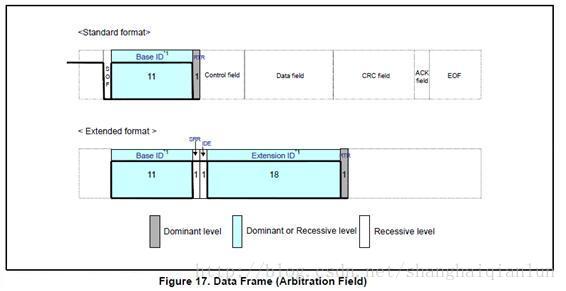
notes 1: About ID:
Standard format ID Yes 11bit, from ID28 To ID18 Sent in turn , High... Is prohibited 7 All bits are hidden .( Prohibit setting :ID=1111111xxxx). So there's a total of (2048-16) individual ID Can be used .
Extended format ID Yes 29 individual bit. basic ID from ID28 To ID18, Expand ID from ID17 To ID0 Express , basic ID And standard format ID identical , High... Is prohibited 7bit All are hidden ,( Prohibit setting : basic ID=1111111xxxx). So there's a total of (2048-16) individual ID Can be used .
In any case , It is impossible for multiple devices on the bus to use the same at the same time ID Transmit data frame .
(3) Control domain , Occupy 6 individual bit, Indicates the number of data bytes to transmit information , The structure of this domain , There are differences between standard and extended formats . Pictured 18 Shown

notes 1: Keep a (r0,r1), Reserved bits must be transmitted at the dominant level , However , The dominant signal can be received on the receiving side 、 The level of any combination of recessive sets .
notes 2: Data length code (DLC), The corresponding relationship between data length code and data bytes is shown in table 7 Shown . The number of bytes of data must be 0-8 Bytes , But the recipient is right DLC=9-15 The situation is not considered a mistake .

(4) Data fields , It is the same for standard or extended formats . This field is the transmitted data , It can be 0 To 8 Bytes , Byte load control field indicates . Data output starts at MSB. Pictured 19 Shown :

(5)CRC Domain , It is the same for standard or extended formats . This field is used to check whether the frame has transmission errors , It consists of 15bit CRC Code and one bitCRC delimiter (delimiter)(separating bit Separate bit)

CRC Is generated by the following polynomial :,CRC The calculation range of is SOF、 Arbitration domain 、 Control domain 、 Data fields . On the receiving side , These fields of the received data frame will be CRC Calculation , If the calculation results are consistent with the received CRC atypism , It indicates that there is a transmission error .
(6)ACK Domain , It is an acknowledgement signal that a frame has been normally received , from 2 individual bit form , One is ACK Of slot, One is ACK The delimiter for (delimiter), Pictured 21 Shown :

notes 1: Of the transmitting unit ACK Domain , The transmitting unit is hidden bit send out ACK slot and ACK Of delimiter.
notes 2: Of the receiving unit ACK Domain , The receiving unit that correctly receives the information is at the end of the receiving frame ACK slot Send an explicit bit, To notify the transmitting unit that it has correctly received , This is also called “sending ACK” or “returning ACK”.
“Returning an ACK”:
As long as all receiving units are not in bus-off Or sleep , Only units that receive information correctly can send ACK. The transmitting unit does not transmit ACK. If there is no transmission unit on the bus , No other unit can receive information , be No ACK Returned . For the establishment of communication , In addition to the transmission unit , At least one unit is required to be able to receive information . If there is... On the bus 2 One or more units can receive information , If either of them receives the message normally , Will have a ACK Returned .
(7) End of the frame , Indicates the end of a frame , from 7 A recessive bit consists of . Pictured 22

1.3 Remote control frame
The remote control frame is that the receiving unit requests the transmitting unit to send a message , The remote control frame has 6 Domains make up . Pictured 23 As it shows , The structure of the data frame is the same as that of the data frame except that there is no data domain .
(1) Frame start (SOF): This field represents the beginning of the data frame .
(2) Competitive domain : This field indicates the priority of the data , Have the same ID Data frame of is requested .
(3) Control domain : This field represents reserved bits and data bytes
(4) CRC Domain : This field is used to check the transmission error of the frame .
(5) ACK Domain : It is a confirmation that the frame has been received normally .
(6) End of the frame : Indicates the end of the remote control frame

Remote control frame and data frame :
- Difference between data frame and remote control frame
- The remote control frame has no data field , In the arbitration domain RTR Bit is hidden level , And data frames RTR Is dominant .
- Data frames without data and remote control frames can be passed through RTR To distinguish
- The remote control frame has no data field , What is the data length code used for ?
- The value of the data length code of the remote control frame represents the data length code of the requested data frame .
- What does a data frame without a data field do ?
- for example , The data frame can be used by each unit as a periodic connection confirmation / The reply , Or the arbitration domain itself contains substantive information .
1.4 Wrong frame
This frame is used to notify that an error occurred during transmission , The error frame consists of an error flag and an error delimiter , The error frame consists of CAN Hardware to send . chart 24 Shows the structure of the error frame .
(1) Error flag : Yes 2 Error flag types : Active error and passive error flags
a) Active error flag :6 A dominant bit
b) Passive error flag :6 A recessive position
(2) Error delimiter : from 8 A recessive bit consists of .

notes 1: Error flags overlap : It depends on the time when each unit connected to the bus detects an error , Error flags may overlap one on top of the other , A total of 12bit length .
notes 2: Active error flag : The error flag output when the unit in the active error state detects an error .
notes 3: Passive error flag : The error flag output when the unit in the passive error state detects an error .
1.5 Overload frame
This frame is used by the receiving unit to notify that it is not ready to receive the frame . It consists of an overload flag and an overload delimiter . chart 25 Shows the structure of the error frame .

(1) Overload sign : from 6 A dominant position consists of , The overload flag has the same structure as the active error flag of the error frame .
(2) Overload delimiter : from 8 A recessive bit consists of , The overload delimiter has the same structure as the error delimiter of the error frame .
notes 1: Error flags overlap : Like the error flag , Depending on the time , Overload signs may overlap one on top of the other , A total of 12bit length .
1.6 Inter frame interval
This frame is used to separate the data frame from the remote control frame . Data and remote control frames can be connected with any previously transmitted frame by inserting an inter frame interval ( Data frame 、 Remote control frame 、 Wrong frame 、 Overload frame ) Separate .
Cannot insert inter frame interval before overload frame and error frame . Pictured 26 Shown .

(1) interval : from 3 A recessive bit consists of . If dominant level is detected during the interval , Then the overload frame must be sent , However , If the th... Of the interval 3bit Is the dominant level , Intervals are considered to be SOF
(2) The bus is idle : Is the hidden level , There is no limit to length ( It can be 0bit Long ). When the bus is in this state , The bus is considered free , Any unit can start sending messages .
(3) Pause transmission ( Transmission pause period ): Yes 8 A recessive bit consists of . Only the segment contained in the frame interval just after the unit in the passive error state sends a message .
1.7 Priority decision
In the bus idle state , The unit that first starts sending the message obtains the sending right .
When multiple units start sending at the same time , Each sending unit arbitrates from the first place in the arbitration domain . The unit with the most dominant level of continuous output can continue to transmit . The lost competing unit is in the next bit Enter the receive operation .
The arbitration process is shown in the figure 27 Shown .

(1) Priority of data frame and remote control frame
Have the same ID When the data frame and remote control frame compete on the bus , The last person in the arbitration section (RTR) Data frames with dominant bits have priority , You can continue to send .
The arbitration process of data frame and remote control frame is shown in Figure 28 Shown .

(2) Priority of standard format and extended format
A standard format ID With the same ID When the remote control frame or extended format data frame competes on the bus , Standard format RTR The dominant bit has priority , You can continue to send .
The arbitration process of standard format and extended format is shown in Figure 29 Shown .

1.8 Bitfill
Bit filling is a kind of periodic resynchronization / The function of sending operation , In order to prevent errors caused by accumulation of timing between receiving nodes , If 5 individual bit The same level is maintained , Then add 1 individual bit Reverse data bit of .
Pictured 30 The bit filling mechanism of the display :

(1) Operation of the transmitting unit
When sending data frames and remote control frames ,SOF-CRC Data between segments , If the same level continues 5bit, Next week bit( The first 6bit) Insert 1bit With the former 5bit Reverse level .
(2) Operation of the receiving unit
When receiving data frames and remote control frames ,SOF-CRC Data between segments , If the same level continues 5bit, The next... Needs to be deleted bit( The first 6bit) Then receive . If this is the first 6bit The level is the same as before 5bit identical , Is considered an error , And send an error frame .
1.9 Wrong kind
Yes 5 There are two types of errors , There may be 2 One or more errors occur at the same time :
- Bit error
- Fill error
- CRC error
- Format error
- ACK error
surface 8 Lists the types of these errors 、 Content 、 Error detection frame and detection unit .

- Bit error is caused by outputting data frames to the bus 、 Remote control frame 、 Wrong frame 、 Unit and output of overload frame ACK Unit of 、 Output the wrong unit to detect .
- Output the hidden level in the arbitration section , But when the dominant level is detected , Will be considered as a failure of Arbitration , Not a bit error .
- When the arbitration section outputs the recessive level as a fill bit , But when the dominant level is detected , Will not be treated as a bit error , It's filling in errors .
- The transmitting unit is at ACK Segment output hidden level , But when the dominant level is detected , Will be judged as... Of other units ACK The reply , Not bit errors .
- Output passive error flag (6 One bit recessive bit ) But when the dominant level is detected , The end condition of the error flag will be followed , Wait for continuous detection of the same 6 The value of a bit ( Explicit or implicit ), It is not considered a bit error .
(2) Format error
- Even if the receiving unit detects EOF(7 The recessive bit of a bit ) Last digit of ( The first 8 bits ) Is the dominant level , It is not considered a format error .
- Even if the receiving unit detects the data length code (DLC) in 9∼15 The value of , It is not considered a format error .
1.10 Output timing of error frame
An error flag is output by the unit that has detected an error , To inform other units .
The error flag of the unit output in the active error state is the active error flag ; The error flag of the unit output in the passive error state is the passive error flag .
After the transmitting unit transmits the error frame , The data frame or remote control frame will be sent again .
The error flag output sequence is shown in the table 9:

1.11 Bit timing
Without resynchronization , The number of bits transmitted per second by the transmitting unit is called the bit rate .1 Bits from below 4 It is composed of three segments .
- Synchronization segment (SS)
- Propagation time period (PTS)
- Phase buffer section 1(PBS1)
- Phase buffer section 2(PBS2)
These paragraphs are also called Time Quantum( The following is called Tq) The smallest time unit of .
1 It's divided into 4 Segments , Each segment consists of several Tq constitute , This is called bit timing .
1 How many... Are there Tq constitute 、 How many... Are there in each segment Tq Composition, etc. can be set . By setting bit sequential . One sampling point can be set so that multiple units on the bus can sample at the same time , The so-called sampling point is when the level on the bus is locked , The level of this latch is the value of the bit . The location of the sampling point is PBS1 At the end of .
surface 10 Describes the role and Tq Count .1 The composition of a bit is shown in the figure 31 Shown .
Segment name | The role of segment | Tq Count | |
Synchronization segment (SS) | Multiple units connected to the bus realize timing adjustment of timing through this segment , So as to synchronously receive and send . The edge of the change from recessive level to dominant level or from dominant level to recessive level is expected to appear in this paragraph . | 1 | 8-25 |
Propagation time period (PTS) | Segment used to absorb physical delays on the network . Including the output delay of the transmitting unit 、 Propagation delay of signal on bus 、 The input delay of the receiving unit . The time of this segment is twice the sum of the above delay time . | 1-8 | |
Phase buffer section 1(PBS1) | When the signal edge cannot appear in SS Segment time , This paragraph is used to correct errors . Because each unit works with its own independent clock , Small clock errors will accumulate ,PBS Segment can be used to absorb this error . To absorb a clock error , stay SJW Increase or decrease within the set range PBS1 and PBS2,PBS1 and PBS2 The bigger it is , The greater the allowable error , But the communication speed will decrease . | 1-8 | |
Phase buffer section 2(PBS2) | PBS1 or IPT Medium to large ( See note 1 and 2) | ||
Resynchronize jump width (SJW) | Due to clock frequency deviation 、 Transmission delay, etc , Some units may lose synchronization .SJW Is the maximum out of sync width that can be corrected . | 1-4*PBS1 | |
notes 1:IPT Represents information processing time , Is the time period starting from the sampling point , Used to calculate the bit level of subsequent bits . This is necessary for the hardware to change the bit level immediately after a sampling point . This time is equal to or less than 2Tq,.
notes 2: Because the sampling point is in PBS1 The end , therefore IPT and PBS2 overlap . When IPT = 2Tq when ,PBS2 It is impossible to choose 1, therefore ,PBS2 Must be 2 To 8Tq.
notes 3: As a result of the resynchronization, the phase buffer segment 1 growth , Or phase buffer section 2 To shorten the . There is an upper limit on the number of lengthened or shortened phase buffers , This upper limit is set by SJW( Resynchronize jump width ) Given . The resynchronization jump width should be set to 1 And the minimum ( This minimum value is 4*PBS1).
The clock information can be obtained from the transition from one bit value to another . Here is an attribute , namely : Only a fixed maximum value of subsequent bits has the same value . This property makes it possible for the bus unit to resynchronize with the bit stream during the frame . The maximum length between the two transitions that can be used for resynchronization is 29 Bit time .

1.12 How synchronization is achieved ?
CAN The bus communication adopts NRZ(Non-Return to Zero, Non return 0) code , The data itself does not carry clock information , That is, there is no synchronization signal at the beginning or end of each bit , The transmitting unit starts transmitting frame data in a bit timing synchronization manner , The receiving unit synchronizes and receives according to the change of bus level .
However , The synchronization between the transmitter and the receiver may be lost due to the clock error or the phase error of the transmission path , Therefore, the receiving unit receives the frame , Its operation timing must be adjusted by hardware synchronization or resynchronization .
1.13 Hardware synchronization
When the bus is idle , The receiving unit detects SOF, The synchronization adjustment process will be executed .“ Implicit ” The level jumps to “ Explicit ” The point in time at the edge of the level is considered to be SS, Regardless of SJW Value
chart 32 Shows the hardware synchronization mechanism .

- If the edge appears in SS in , Phase error along the e=0;
- If the edge is at the acquisition point (PBS1 Before the end ) Before ,e>0;
- If the edge is behind the acquisition point ,e<0;
1.14 Resynchronization mechanism
The resynchronization operation is performed when a bus level change is detected during reception .
Whenever an edge is detected ( Change of bus level ), The transceiver unit is based on SJW Value by increasing PBS1 Segment or reduce PBS2 paragraph , To adjust synchronization . but , If an excess occurs SJW When the error of the value , The maximum adjustment cannot exceed SJW value .
chart 33 Shows the resynchronization mechanism .

1.15 Adjust synchronization rules
The implementation of hardware synchronization and resynchronization follows the following rules :
1) stay 1 Bit time ( Or in 2 Between sampling points ), Only one synchronization is allowed ( Or just make one synchronization adjustment ).
2) Only when the bus level before the sampling point is different from that after the edge , This edge can only be used to adjust synchronization .
3) If the edge of the change from recessive level to dominant level occurs , And the conditions (1) and (2) Satisfy , Will synchronize .
4) If a signal edge from the recessive level to the dominant level occurs during the inter frame gap ( Except for the first place in the gap ), Hardware synchronization is always performed .
5) If a signal edge from all other recessive levels to dominant levels occurs , Then perform resynchronization .
6) If the dominant level output by the transmitting unit itself is detected to have a delay , Do not perform resynchronization .
边栏推荐
猜你喜欢


随机推荐
Abnova ACTN4纯化兔多克隆抗体说明书
静态双位置继电器GLS-3004K/DC220V
2022年起重机械安全管理考试题库及答案
论文阅读_关系抽取_CASREL
DSP7 环境
mysql json
一款MVC5+EasyUI企业快速开发框架源码 BS框架源码
PaddlePaddle模型服务化部署,重新启动pipeline后出现报错,trt报错
如何让社交媒体成为跨境电商驱动力?这款独立站工具不能错过!
不归零编码NRZ
抖音x-bogus和_signature参数分析
如何解决独立站多渠道客户沟通难题?这款跨境电商插件一定要知道!
Does the network disk also roll inside?
Pta:6-29 application of virtual base classes - people, teachers and students
thinkphp6 模版替换
2022金属非金属矿山(露天矿山)安全管理人员考试题模拟考试题库及答案
Introduction and use of MySQL view
const理解之一
VGG 中草药识别
20000 words + 20 pictures | details of nine data types and application scenarios of redis