当前位置:网站首页>[hdlbits questions] Verilog language (3) modules: hierarchy section
[hdlbits questions] Verilog language (3) modules: hierarchy section
2022-07-25 19:18:00 【Linest-5】
Catalog
Write it at the front
This part mainly gives answers and waveform simulation images directly , The details of some topics may be explained .
Modules: Hierarchy
Module
Example module
Connecting the signal to the port of the module by name allows the wires to remain properly connected , Even if the port list changes .
mod_a instance2 (
.out(wc),
.in1(wa),
.in2(wb)
);
The above line instantiates a named “instance2” Type of module , Then send the signal ( Outside the module ) Connect to a The port of 、 be known as The port and name of are The port of . Please note that , The order of ports is irrelevant here , Because no matter where it is in the port list of sub modules , Will establish the correct name .
module top_module (
	input a,
	input b,
	output out
);
    mod_a mod_a_inst (
        .out(out),
        .in1(a),
        .in2(b)
    );

endmodule
Simulation waveform

Module pos
You will get a named mod_a Module , The module has 2 Output and 4 Inputs ( In this order ).
You must place 6 Ports are connected to the ports of the top-level module in this order .
module top_module (
    input a,
    input b,
    input c,
    input d,
    output out1,
    output out2
);
    mod_a u_mod_a(out1,out2,a,b,c,d);

endmodule
Simulation waveform

Module name
Example module , The connection corresponding to the port .
module top_module (
    input a,
    input b,
    input c,
    input d,
    output out1,
    output out2
);
    mod_a mod_a_inst (
        .in1(a),
        .in2(b),
        .in3(c),
        .in4(d),
        .out1(out1),
        .out2(out2)
    );

endmodule
Simulation waveform

Module shift
You will get a module with two inputs and one output ( Realization D trigger ). Instantiate three of them , Then link them together to form a length of 3 The shift register of . This port needs to be connected to all instances .
The module provided to you is :
module my_dff (
input clk,
input d,
output q
);
Please note that , Internal connection , You need to declare some wires . Be careful when naming circuits and module instances : The name must be unique .
module top_module (
	input clk,
	input d,
	output q
);

	wire      shift1;
	wire	  shift2;

my_dff my_dff_inst(
	.clk(clk),
	.d(d),
	.q(shift1)
	);

my_dff my_dff_u(
	.clk(clk),
	.d(shift1),
	.q(shift2)
	);

my_dff inst_my_dff(
	.clk(clk),
	.d(shift2),
	.q(q)
	);

endmodule
Simulation waveform

Module shift8
A module with two inputs and one output ( Implement a set of 8 D trigger ). Instantiate three of them , Then link them together , The formation length is 3 Of 8 Bit width shift register . Besides , Create a 4 Yes 1 multiplexer ( Did not provide a ), The output content of the multiplexer depends on : Input d Place the value of the , first D after , After the second multiplexer , Or the third D Value after trigger . In essence , Select the number of cycles to delay input , From zero to three clock cycles .
module top_module (
    input          clk,
    input  [7:0]   d,
    input  [1:0]   sel,
    output [7:0]   q
);

	wire [7:0]    shift1;
	wire [7:0]	  shift2;
	wire [7:0]	  shift3;

my_dff8 my_dff8_inst(
	.clk(clk),
	.d(d),
	.q(shift1)
	);

my_dff8 my_dff8_u(
	.clk(clk),
	.d(shift1),
	.q(shift2)
	);

my_dff8 inst_my_dff8(
	.clk(clk),
	.d(shift2),
	.q(shift3)
	);

always @(*) begin
	case(sel)
		0:begin
			q = d;
		end
		1:begin
			q = shift1;
		end
		2:begin
			q = shift2;
		end
		3:begin
			q = shift3;
		end
	endcase
end

endmodule
Simulation waveform

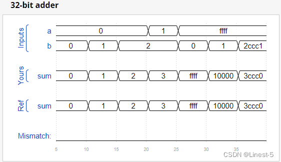
Module add
An executive 16 Bit addition module . Instantiate two of them to create 32 Bit adders . One add16 The module calculates the bottom of the addition result 16 position , And the second one. add16 The module receives the execution from the first adder , Upper limit of calculation result 16 position .32 Bit adders do not need to handle carry ( hypothesis 0) Or execution ( Ignore ), But the internal module needs to be processed to work properly .( let me put it another way , Module execution 16 position a + b + cin, And the module executes 32 position a + b).
module top_module(
    input  [31:0]   a,
    input  [31:0]   b,
    output [31:0]   sum
);

wire  [15:0]   sum1;
wire  [15:0]   sum2;
wire           cout;

add16 add16_inst_l(
	.a(a[15:0]),
	.b(b[15:0]),
	.cin('d0),
	.cout(cout),
	.sum(sum1)
	);

add16 add16_inst_h(
	.a(a[31:16]),
	.b(b[31:16]),
	.cin(cout),
	.sum(sum2)
	);

assign sum = {sum2,sum1};

endmodule
Simulation waveform

Module fadd
An executive 16 Bit addition module . You must instantiate two of them to create 32 Bit adders . A module calculates the bottom of the addition result 16 position , And the upper limit of the calculation result of the second module 16 position .32 Bit adders do not need to handle carry ( hypothesis 0) Or execution ( Ignore ).
module add16 (
input[15:0] a,
input[15:0] b,
input cin,
output[15:0] sum,
output cout
);
In each ,16 A complete adder ( modular , Did not provide a ) Instantiated to actually perform addition .
You must write a complete adder modular
module add1 (
input a,
input b,
input cin,
output sum,
output cout
);
There are three modules in this design :
top_module Top level modules , There are two of them add16, Provide a 16 Bit adder module , from 16 individual add1 One 1 Bit complete adder module .
module top_module (
    input [31:0] a,
    input [31:0] b,
    output [31:0] sum
);

wire  [15:0]   sum1;
wire  [15:0]   sum2;
wire           cout;

add16 add16_inst_l(
	.a(a[15:0]),
	.b(b[15:0]),
	.cin('d0),
	.cout(cout),
	.sum(sum1)
	);

add16 add16_inst_h(
	.a(a[31:16]),
	.b(b[31:16]),
	.cin(cout),
	.sum(sum2)
	);
assign sum = {sum2,sum1};

endmodule

module add1 (
	input a,
	input b,
	input cin,
	output sum,
	output cout
);

assign {cout,sum} = a+b+cin;

endmodule
Simulation waveform

Module cseladd
The disadvantage of choosing adder is the delay of adder calculation , It is necessary to get the carry value of the upper level before the calculation of the next level . The improved method is to use the selective adder . The first stage adder is the same as before , But we copy the second level adder , Suppose a carry is 0, The other carry is 1, Use 2 Yes 1 Multiplexer to choose which result is just right . Provide the same module as the previous exercise , The module will have two 16 Add the digits , And generate a carry sum 16 The bit sum must instantiate three of them , To use your own 16 position 2 Yes 1 Multiplexer construction carry select adder .
module add16 (
input[15:0] a,
input[15:0] b,
input cin,
output[15:0] sum,
output cout
);
module top_module(
    input  [31:0]   a,
    input  [31:0]   b,
    output [31:0]   sum
);

wire  [15:0]   sum1;
wire  [15:0]   sum2;
wire  [15:0]   sum3;
wire           cout;

add16 add16_inst_l(
	.a(a[15:0]),
	.b(b[15:0]),
	.cin('d0),
	.cout(cout),
	.sum(sum1)
	);

add16 add16_inst_h_0(
	.a(a[31:16]),
	.b(b[31:16]),
	.cin('d0),
	.sum(sum2)
	);

add16 add16_inst_h_1(
	.a(a[31:16]),
	.b(b[31:16]),
	.cin('d1),
	.sum(sum3)
	);

always @(*) begin
	case(cout)
		0:begin
			sum = {sum2,sum1};
		end
		1:begin
			sum = {sum3,sum1};
		end
	endcase
end

endmodule
Simulation waveform
Module addsub
adder - The subtracter can be constructed from the adder by selectively negating one of the inputs , This is equivalent to inverting the input and then adding 1.
The end result is a circuit that can perform two operations :(a + b + 0) and (a + ~b + 1).
And 0 XOR remains unchanged , And 1 XOR is equivalent to negation .
Provides a 16 Bit adder module , You need to instantiate it twice :
module add16 (
input[15:0] a,
input[15:0] b,
input cin,
output[15:0] sum,
output cout
);
Use 32 A wide XOR Grid , stay sub by 1 Time reversal b Input .( It can also be seen as b[31:0]XORed,
Child copied 32 Time . Look at the copy operator ) Also connect the sub input to the body of the adder .
module top_module(
    input  [31:0]   a,
    input  [31:0]   b,
    input           sub,
    output [31:0]   sum
);

reg   [31:0]   c;
wire  [15:0]   sum1;
wire  [15:0]   sum2;
wire           cout;

always @(*) begin
	if (~sub) begin
		c = b;
	end
	else begin
		c = ~b;
	end
end

add16 add16_inst_l(
	.a(a[15:0]),
	.b(c[15:0]),
	.cin(sub),
	.cout(cout),
	.sum(sum1)
	);

add16 add16_inst_h(
	.a(a[31:16]),
	.b(c[31:16]),
	.cin(cout),
	.sum(sum2)
	);

assign sum = {sum2,sum1};

endmodule
Simulation waveform

边栏推荐
- 【DETR用于3D目标检测】DETR3D: 3D Object Detection from Multi-view Images via 3D-to-2D Queries
- 微信小程序 29 热搜榜的完善②
- [cloud native kubernetes] management of secret storage objects under kubernetes cluster
- CLIP还能做分割任务?哥廷根大学提出一个使用文本和图像prompt,能同时作三个分割任务的模型CLIPSeg,榨干CLIP能力...
- 【云原生之kubernetes】kubernetes集群下Secret存储对象的管理
- Pymoo学习 (7):并行化Parallelization
- [record of question brushing] 21. Merge two ordered linked lists
- 【加密周报】加密市场有所回温?寒冬仍未解冻!盘点上周加密市场发生的重大事件!
- Fearless of high temperature and rainstorm, how can Youfu network protect you from worry?
- 聊聊sql优化的15个小技巧
猜你喜欢

Pymoo learning (6): termination conditions

Wechat campus maintenance application applet graduation design finished product of applet completion work (3) background function

Improvement of wechat applet 29 hot search list ②

【iniparser】项目配置工具iniparser的简单使用

【加密周报】加密市场有所回温?寒冬仍未解冻!盘点上周加密市场发生的重大事件!

Pixel2mesh generates 3D meshes from a single RGB image eccv2018
![[open source project] stm32c8t6 + ADC signal acquisition + OLED waveform display](/img/5f/413f1324a8346d7bc4a9490702eef4.png)
[open source project] stm32c8t6 + ADC signal acquisition + OLED waveform display

小程序毕设作品之微信校园维修报修小程序毕业设计成品(7)中期检查报告

modelsim和quartus联合仿真PLL FIFO等IP核
微信小程序 29 热搜榜的完善②
随机推荐
Have you ever seen this kind of dynamic programming -- the stock problem of state machine dynamic programming (Part 1)
HTTP缓存通天篇,可能有你想要的
Youfu force supercomputing provides customized high-performance computing services for customers
基于Mysql-Exporter监控Mysql
QT compiled successfully, but the program could not run
【加密周报】加密市场有所回温?寒冬仍未解冻!盘点上周加密市场发生的重大事件!
一个函数中写多少行代码比较合适呢? 代码整洁之道
JS 基本类型 引用类型 深/浅克隆复制
新瓶装老酒--近期APT32(海莲花)组织攻击活动样本分析
Deng Qinglin, a technical expert of Alibaba cloud: Best Practices for disaster recovery and remote multi activity across availability zones on cloud
高并发下如何保证数据库和缓存双写一致性?
HTTP cache tongtianpian, there may be something you want
Wechat campus maintenance and repair application applet graduation design finished product of applet completion work (6) opening defense ppt
[open source project] stm32c8t6 + ADC signal acquisition + OLED waveform display
MES管理系统有什么应用价值
Juzhi cloud computing opens a new era to the "proprietary cloud" of Youfu network
MySQL sub query (selected 20 sub query exercises)
帝国CMS整站|手机号/QQ靓号商城源码|适配移动端
Pymoo学习 (5):收敛性分析
【iniparser】项目配置工具iniparser的简单使用