当前位置:网站首页>Digital circuit - adder
Digital circuit - adder
2022-06-26 01:03:00 【Salted fish shell】
digital circuit —— adder
We learned about doors before , A circuit is a combination of gates .
Circuits can be divided into two categories , Combinational circuits and sequential circuits .
But as the knowledge of computer and programming , What we need to know is how to use combinational circuits . So this article is about the operation of combinational circuits ( Boolean operation of circuit .)
It's OK to look at the derivation process . Suggestion or check , Get to know .
Combinational circuit ( Skipping )
A circuit whose output is determined only by the input value
Take the output of one door as the input of another , The gate can be combined into a circuit .
Pictured above , The outputs of the two and gates are used as inputs to the OR gate .
Be careful :
- A It is the input of two and gates at the same time .
- There is no connection point at the intersection of two crossed connecting lines , It should be regarded as a connecting line that spans one , They have no influence on each other
circuit analysis Let's look at it backwards , Analyze by door
- If X=1 shows ,D and E At least one is 1.
- If D yes 1, be AB It has to be 1
- If E yes 1, be AC It has to be 1
The truth table is as follows
| A | B | C | D | E | X |
|---|---|---|---|---|---|
| 0 | 0 | 0 | 0 | 0 | 0 |
| 0 | 0 | 1 | 0 | 0 | 0 |
| 0 | 1 | 0 | 0 | 0 | 0 |
| 0 | 1 | 1 | 0 | 0 | 0 |
| 1 | 0 | 0 | 0 | 0 | 0 |
| 1 | 0 | 1 | 0 | 1 | 1 |
| 1 | 1 | 0 | 1 | 0 | 1 |
| 1 | 1 | 1 | 1 | 1 | 1 |
The three outputs are 8 Two combinations ( 23). The middle shows the middle value of the circuit (D and E).
At this point, we can use Boolean algebra to represent the circuit . because A circuit is a set of interrelated gates , So it means that Boolean expressions are combinations of Boolean operations .
In this circuit , There are two expressions . The output of each operation is the input of the or operation .
therefore ~(AB+AC) This The Boolean expression represents This circuit
The point of detail is
- (AB=D AC=E)
- D+E=X
- Then refer to the truth table .
Let's start from the other direction , Draw the corresponding truth table and logic block diagram from Boolean expression .
for example A(B+C) In this expression , Two input values B and C Or operation . This result and A As input to the and operation , To produce results . The corresponding logic block diagram is as follows

《 Introduction to computer science 》P69
analysis :( Door relation )
- A(B+C) by 1, be A And B+C All must be 1
- B+C by 1 be B and C Not all for 0
- A by 0 The output of 0(A(B+C))
The corresponding truth table is as follows
| A | B | C | B+C | A(B+C) |
|---|---|---|---|---|
| 0 | 0 | 0 | 0 | 0 |
| 0 | 0 | 1 | 1 | 0 |
| 0 | 1 | 0 | 1 | 0 |
| 0 | 1 | 1 | 1 | 0 |
| 1 | 0 | 0 | 0 | 0 |
| 1 | 0 | 1 | 1 | 1 |
| 1 | 1 | 0 | 1 | 1 |
| 1 | 1 | 1 | 1 | 1 |
We can use any row of the truth table to verify the results .
Like the third line
A=0 B =1 C=0 B+C=1+0=1( Or gate , There's an output 1 Just go ) A(B+C)=0(B+C=1)=0
( And gate , Both outputs must be the same 1 Just output 1, Otherwise output 0)
Logic Algebra ( Boolean algebra ) It represents a logical relationship , Not a quantitative relationship .
Compare the last column of these two examples , Exactly the same . This is it. Circuit equivalence
Circuit equivalence : Corresponding to each input value combination , Both circuits produce identical outputs
After understanding the basic knowledge above , We can use it Provable laws of Mathematics To design logic circuits .
| nature | And | or |
|---|---|---|
| Commutative law | AB=BA | A+B=B+A |
| Associative law | (AB)C=A(BC) | (A+B)+C=A+(B+C) |
| Distribution rate | A(B+C)=(AB)+(AC) | A+(BC)=(A+B)+(A+C) |
| Identity | A1=A | A+0=A |
| repair | A(A’)=0 | A+(A’)=1 |
| Virtue · Morgan's law | (AB)‘=A’OR’B’ | (A+B)‘=A’B’ |
Virtue · Morgan's law :
This law states , For two variables Non operational with the result of the operation , It is equal to or operate on each variable after non operation .
That is to say, the output of and gate is inversed , Equivalent to first finding the inverse of each signal , Then pass them to the OR gate
(AB)‘=A’+B’
This The second part of the law Cent is , Yes Two variables or the result of an operation , be equal to After non operating on each variable, and operating on them .
That's right Or gate output inversion , Equivalent to first finding the inverse of each signal , They are being introduced into And gate :
(A+B)‘=A’B’
adder
In digital circuits , frequently-used Combinational logic circuit Yes adder 、 Encoder 、 Decoder, etc , Here we mainly introduce the adder
The most basic operation a computer can perform is to add two numbers . So how is it realized through combinational circuits ? This is the focus of this article ~.
Same as addition in all counting systems , The two one. Sum of binary numbers The result may be Carry value . Binary ,1+1=10. A circuit that computes two digits and generates the correct carry is called a half adder .
adder : A circuit that performs addition operations on binary systems
Half adder : A circuit that computes two digits and generates the correct carry
Full adder : Calculate the sum of two digits . And consider the circuit of carry input
Half adder
Seeking binary A and B All the possibilities of , The truth table is as follows :
| A | B | and | carry |
|---|---|---|---|
| 0 | 0 | 0 | 0 |
| 1 | 0 | 1 | 0 |
| 0 | 1 | 1 | 0 |
| 1 | 1 | 0 | 1 |
Be careful :1+1=10 ( Binary is 2 use 10 Express , A single gate circuit only outputs 1 position , So He Wei 0, Carry is 1)
If the sum and carry columns are compared with the output of various gates , Will find ~—— And the corresponding XOR gate , Carry and gate
So this half adder is expressed as follows :
The above image is taken (https://www.bilibili.com/video/BV1Hi4y1t7zY?p=5&vd_source=743ccd142aebf9f406282dcc02bc441d)
The above image is taken (https://www.bilibili.com/video/BV1Hi4y1t7zY?p=5&vd_source=743ccd142aebf9f406282dcc02bc441d)
The Boolean expression is as follows :
								  and =A⊕B( Exclusive OR gate )
							     carry =AB	( And gate )
XOR gate truth table
| A | B | X |
|---|---|---|
| 0 | 0 | 0 |
| 0 | 1 | 1 |
| 1 | 0 | 1 |
| 1 | 1 | 0 |
Be careful : Half adders do not carry ( Carry input ) Consider in the calculation , So the half adder intelligently calculates the sum of two digits , The sum of two multi bit binary numbers cannot be calculated .
Calculation 01+01 And , Shown by the following ( Add low and low , High order and high order are added . Up and down .)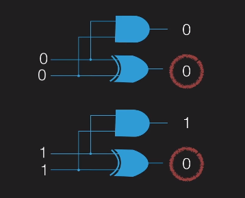
The above image is taken (https://www.bilibili.com/video/BV1Hi4y1t7zY?p=5&vd_source=743ccd142aebf9f406282dcc02bc441d)
Now this value is wrong ! The value obtained below is not transmitted to the above . I.e. cannot accept carry .
The above image is taken (https://www.bilibili.com/video/BV1Hi4y1t7zY?p=5&vd_source=743ccd142aebf9f406282dcc02bc441d)
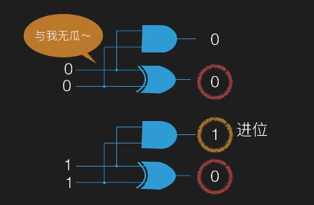
Full adder
Total plus : Realize the addition of two one bit binary numbers , And consider the carry from the low bit .

The above image is taken (https://www.bilibili.com/video/BV1Hi4y1t7zY?p=5&vd_source=743ccd142aebf9f406282dcc02bc441d)
A full adder can be constructed from two half adders . Summation input Must be Carry input and the sum of two input values . in other words , Add the sum from the half adder to the carry input .
The above image is taken (https://www.bilibili.com/video/BV1Hi4y1t7zY?p=5&vd_source=743ccd142aebf9f406282dcc02bc441d)
Analyze the value ( The specific circuit is unnecessary ), This circuit has 3 Inputs , The original digits A and B And carry input Ci. So the truth table has 8 That's ok (3 Inputs 23=8, Any problems? ? No problem )
| A | B | Ci | Y | Co |
|---|---|---|---|---|
| 0 | 0 | 0 | 0 | 0 |
| 0 | 0 | 1 | 1 | 0 |
| 0 | 1 | 0 | 1 | 0 |
| 0 | 1 | 1 | 0 | 1 |
| 1 | 0 | 0 | 1 | 0 |
| 1 | 0 | 1 | 1 | 0 |
| 1 | 1 | 0 | 0 | 1 |
| 1 | 1 | 1 | 1 | 1 |
Finally, simplify the formula . Just ignore it
Y=(A⊕B)⊕Ci
Co=AB+Ci(A⊕B)


The above image is taken (https://www.bilibili.com/video/BV1Hi4y1t7zY?p=5&vd_source=743ccd142aebf9f406282dcc02bc441d)
8 The total adders can be combined to calculate 8 Bit binary operation ~ 8 Bit binary is 1 Bytes ~.
Add two octet values , It needs to be copied 8 Sub full adder circuit . One Bit value output Will act on The next bit is worth the carry input . Far right The carry input is 0, The leftmost Carry output will be discarded ( Usually an overflow error is generated , Certain , I just 8 An adder can also display 8 position , To the first 9 Bit is not super ~)
Reference material
- Before programming, you'd better know the basic hardware and computer knowledge ( digital circuit ) https://www.bilibili.com/video/BV1Hi4y1t7zY?p=5&vd_source=743ccd142aebf9f406282dcc02bc441d
- 《 Introduction to computer science The first 5 edition 》
边栏推荐
猜你喜欢


随机推荐
Android cache usage tool class
使用VS2022編譯Telegram桌面端(tdesktop)
Return value is object type method call equals()
1-11solutions to common problems of VMware virtual machine
Leetcode 513. Find the value in the lower left corner of the tree
关于HC-12无线射频模块使用
Mpu6050 reads the ID incorrectly and 0xd1 occurs (the correct ID should be 0x68 or 0x69). Solution.
debezium
Penetration tool -burpsuite
1-9network configuration in VMWare
制作3D浪漫炫酷相册【附源码】
安卓缓存使用工具类
Flex & Bison 开始
The cache page stores the initial parameters after the route jump under the react + router framework
[understanding of opportunity -30]: Guiguzi - internal "chapter - empathy, stand on the other side's position and narrow the psychological distance with the other side
如何有效地推廣產品
Example: use C # Net to teach you how to develop wechat official account (21) -- using wechat to pay online collection: H5 method
Optimized three-dimensional space positioning method and its fast implementation in C language
[TSP problem] solving traveling salesman problem based on Hopfield neural network with matlab code
统一网关Gateway