当前位置:网站首页>Stm32cubemx quadrature encoder
Stm32cubemx quadrature encoder
2022-07-25 02:59:00 【ASWaterbenben】
Recently, I encountered the need to obtain the function of orthogonal coding , So come back and study STM32CubeMX Encoder function , It has been updated before STM32 Timer function , However, the principle of the quadrature encoder of the balance car was not clear , Just use the pulse input function directly to get things done , Now I'm paying for my former Youth , But see the existing Encoder The instructions are relatively simple , Therefore, it is considered to contribute to developers , After I research it clearly, I will write a blog .
Coming back to the book , The quadrature encoder is usually installed on the motor , Coaxial with the main shaft of the motor rotor , Some are connected to the encoder through the main shaft to reduce or accelerate the gear set , There are generally two kinds of encoders: grating encoder and magnetic pole encoder , The output pulses of forward rotation and reverse rotation are like the following figure 
STM32 It has the function of processing orthogonal pulses , That is, in the timer Encoder Pattern
Specific operation :
STM32CubeMX To configure
1. open STM32CubeMX, Choose your own chip , Here I use STM32F429IGT6 Take... For example ;
2. Set up the system 、 Basic operation of clock
SYS
RCC
3. Timer settings
Here I choose TIM3,TIM3 Bit Universal timer , There are many general timers for general chips
Combined Channels use Encoder Mode( Encoder mode )
After selecting this mode TIM3 Of CH1 and CH2 It becomes an encoder interface , Remember the corresponding two interfaces , Then connect the encoder signal to these two ports , My is PA6 and PA7
The parameter settings below are set according to the requirements , Because I need to record the rising and falling edges of the encoder , So here we choose Encoder Mode TI1 and TI2, This mode will AB The rising and falling edges of both sets of pulses are counted , It's counting 4 Time , Students who do not need to be so precise can put the pre frequency division coefficient (Prescaler) It is amended as follows 4-1, Then pulse detection 4 Pulses will count 1 Time , Filter depends on individual , I use DuPont line to connect directly , distance 10cm No, so I set 0, You can see how to choose STM32 Chinese Reference Manual , Lazy people look at the picture below 

4. Serial port settings
To facilitate observation , You need to send the corresponding rotation direction through the serial port , Rotate the count value to the serial port debugging assistant .
Because the chip is only used to send data , There will be no interruption , Directly select asynchronous serial port 
5. Finally, configure the clock tree
This is handled by everyone , Each chip is different , Finally let the middle HCLK(MHz) by 72 that will do 
6. Project configuration
The development environment I use is Keil5, So in Toolchain/IDE I chose MDK-ARM

When generating code, put Generated files Select the first item in , Otherwise h Document and c Documents are mixed , It's hard to look at 
7. Click on the top right corner GENERATE CODE Generate code
Code changes
1. Serial port code modification
For convenience , use printf Function output information , So it needs to be in the serial port /* USER CODE BEGIN 0 */ Add serial port redirection function , As shown below :
/* USER CODE BEGIN 0 */
#include <stdio.h>
struct __FILE
{

	int handle;
};
FILE __stdout;
void _sys_exit(int x)
{

	x = x;
}
int fputc(int ch, FILE *f)
{

	while((USART1->SR&0X40)==0);// Cycle to send , Until it's sent
	USART1->DR=(uint8_t)ch;
	return ch;
}

/* USER CODE END 0 */
2.main.c modify
First, add stdio.h The inclusion of , Convenient for the back printf Output
stay main.c Of /* USER CODE BEGIN Includes */ Add the following code :
/* USER CODE BEGIN Includes */
#include <stdio.h>
/* USER CODE END Includes */
Then you need several variables , Respectively
| Variable name | Variable usage |
|---|---|
| Direction | Encoder rotation direction |
| counter | Main function count , be used for printf The timing segment of the function is sent |
| enc1 | Encoder count (0~65535) |
| enc1_old | Last encoder count (0~65535) |
| enc2 | enc1 Carry of |
| enc | Final encoder count |
Defining variables , stay /* USER CODE BEGIN 1 */ Add the following code
/* USER CODE BEGIN 1 */
  uint8_t Direction;
  uint16_t counter;
  uint16_t enc1 = 0,enc1_old = 0;
  int16_t enc2 = 0;
  int32_t enc;
  /* USER CODE END 1 */
Start encoder interpretation , stay /* USER CODE BEGIN 2 */ Add encoder startup function
/* USER CODE BEGIN 2 */
  HAL_TIM_Encoder_Start(&htim3, TIM_CHANNEL_ALL);
/* USER CODE END 2 */
In circulation , That is to say /* USER CODE BEGIN 3 */ After that, add the reading encoder value function, carry processing function and print output function :
/* USER CODE BEGIN 3 */
	Direction = __HAL_TIM_IS_TIM_COUNTING_DOWN(&htim3);
    enc1 = (uint32_t)(__HAL_TIM_GET_COUNTER(&htim3));	// Get the value of the timer
	if((Direction == 0) &(enc1 < enc1_old))				// The value of positive rotation decreases , Description carry
	{

		enc2++;
	}
	if((Direction == 1) &(enc1 > enc1_old))				// The reverse rotation value becomes smaller , Description borrow
	{

		enc2--;
	}
	enc1_old = enc1;									// to update enc1_old, For the next calculation
	enc = enc2<<16 | enc1;								// Calculate the total value of the current count , belt +- Number
	counter++;											// Main function count
	if(counter>1000)									// The main function runs about 1ms, This is for every 1000ms Send once
	{

		counter = 0;									// The count value is cleared
		printf("Dir %d, Enc2 %d, Enc1 %d, ENC %d\r\n",Direction,enc2,enc1,enc);// Print relevant count data
	}
	HAL_Delay(1);
  }
  /* USER CODE END 3 */
At this point, the code has been completely modified , Compile and download to the chip , Wait for wiring test
Wiring test
The encoder I use is 5v A magnetic pole encoder for power supply , But the final interface should be VCC、GND、A、B Four interfaces , At this time, connect as follows
| Encoder | STM32 |
|---|---|
| A | TIM3_CH1 |
| B | TIM3_CH2 |
| VCC | 5V level |
| GND | And STM32 Common land |
After connecting, you can power on , Open the serial debugging assistant , Connect the serial port 1
You will receive the following data , At this time, you can see the change of the value by turning the encoder 
thus , Encoder function has been completed .
		  Good Game!!!!!!

 Next, we will launch a series of sharing about serial port use , Apes in need, please pay attention !!!!!
You are welcome to reprint and quote the above content , Just mark the source !!!!!
边栏推荐
- 6. Object storage
- File file name change
- Execution methods with static code blocks and child and parent classes
- Js a simple way to store several objects in an array
- Sequence diagram of UML diagram series
- Wechat sports field reservation of the finished works of the applet graduation project (5) assignment
- Publish the project online and don't want to open a port
- [Kali's sshd service is enabled]
- "Introduction to interface testing" punch in day08: can you save all parameters to excel for test data?
- Wechat sports field reservation of the finished works of the applet graduation project (7) mid-term inspection report
猜你喜欢

Operator explanation - C language
Banana pie bpi-m5 toss record (2) -- compile u-boot
![[jailhouse article] certify the uncertified rewards assessment of virtualization for mixed criticality](/img/12/1763571a99e6ef15fb7f9512c54e9b.png)
[jailhouse article] certify the uncertified rewards assessment of virtualization for mixed criticality

Riotboard development board series notes (4) -- using Vpu hardware decoding
![[stm32f130rct6] idea and code of ultrasonic ranging module](/img/a6/1bae9d5d8628f00acf4738008a0a01.png)
[stm32f130rct6] idea and code of ultrasonic ranging module
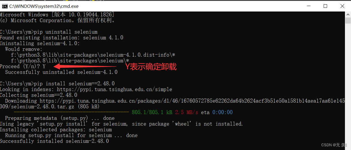
Resolved (the latest version of selenium reported an error) attributeerror: module 'selenium webdriver‘ has no attribute ‘PhantomJS‘

Tp5.1 initialize initialization method (not \u initialize)

JS foundation -- task queue and event loop

Riotboard development board series notes (6) -- buildreoot building system image

Application method and practical case of sqlmap of penetration test SQL injection
随机推荐
Keras load history H5 format model error: attributeerror 'STR' object has no attribute 'decode‘
Threat report in June: new bank malware malibot poses a threat to mobile banking users
[jailhouse article] scheduling policies and system software architectures for mixed criticality
Unity refers to a variable in another class (its own instance)
Publish the project online and don't want to open a port
Pypi counts the number of Downloads
Request and response
Ffmpeg 4.3 add custom demuxer
Dynamic programming -- Digital DP
DOM node type
Win10 -- open the hosts file as an administrator
Selenium framework operation steelth.min.js file hides browser fingerprint features
Tensorflow's study notes (I)
Execution methods with static code blocks and child and parent classes
Mark down learning
Wechat sports field reservation of applet completion works applet graduation design (8) graduation design thesis template
Arduino IDE for raspberry PI Pico development firmware localization installation tutorial
Object.defineproperty use
Tp5.1 initialize initialization method (not \u initialize)
Wechat sports field reservation of the finished works of the applet graduation project (6) opening defense ppt