当前位置:网站首页>A transformer can only convert alternating current. How can I convert direct current?
A transformer can only convert alternating current. How can I convert direct current?
2022-06-23 15:22:00 【Mr. Lin teaches SCM】
How to handle 12 Volt to 5V Well ? It can be realized through transformer , But the transformer can only convert alternating current , How do you convert DC power ?

I once naively thought it was such a way to reduce blood pressure , For example, the load is 5 o , Then you have to get 5 Volt drop , According to the series partial pressure principle , It needs to be connected in series 7 Ohm resistance , The load will get a voltage drop of five volts , This method can really be implemented 12 V to v , But what if the load resistance changes ?
When it becomes 10 Ou Shi , At this time, the voltage on the load becomes 7V, To ensure that the voltage applied to both ends of the load is 5 v , We need to take R1 Replace with 14 Ohm resistance , So we can get five volts , But the problem is that the resistance of the load changes all the time , How can we ensure that the voltage at both ends of the load is maintained at when the load resistance changes 5V Well ?
The article is relatively long , More words , You can first open the avatar and pay attention to me , Then take your time ,/// Insert a : At the beginning of this year, I recorded a set of systematic introductory single chip microcomputer tutorial , If you want, just ask me for it. It's free , I can send a private message ~ Click the black font in the lower left corner of my avatar and I can also get it . I've been relatively idle recently , Take me to finish the design , Take students to provincial or above competitions ///
The method is to adjust all the time R1 Value , This is a little difficult for people , Because we have to measure the voltage of the load , One side to adjust R1 Value , If the work is left to manual work , Obviously, it can't be done well , In response to this question , Intelligent man invented an intelligence R1.

intelligence R1 It's actually a bunch of circuits , It can help us measure the output voltage Vout, Then adjust the resistance for yourself , Keep the output at 5 v , Its core is the in-phase amplifier , In the mold , Amplifiers are very difficult to learn , But it is also very simple if it is only applied .
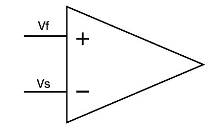
In this circuit , We just need to know when VS Greater than VF When , Its output voltage decreases , When VS Less than VF When , Its output voltage increases .
3.3V Is the reference voltage of the amplifier ,D It's a regulator , Even if the input voltage changes , It can also stabilize the voltage at 3.3 v , So the reference voltage of the amplifier VF Namely 3.3 v .

This is the sampling voltage , It is related to the output voltage , When Vout At five volts , Amplifier input VS be equal to 3.3 v , If Vout Greater than five , be responsible for VS Greater than 3.3 v , When Vout be equal to 5V When , The rest 7V Applied to the triode , At this time, the triode works in the linear amplification region .
It doesn't matter if you don't know what a linear amplification region is , We only need to know that when the output voltage of the amplifier increases , The output current of the triode also increases , When the output voltage of the amplifier decreases , The output current of the triode is also reduced , Its voltage stabilizing principle is as follows .

If the input voltage or load change is Vout Greater than 5 v , be VS Greater than VF, At this time, the output of the amplifier UB smaller , At the same time, the output current of the triode becomes smaller , This causes the load voltage to drop again 5 v , Again , When Vout Less than 5 When you fall ,VS Less than VF, At this time, the output of the amplifier UB Bigger , This causes the load voltage to rise again 5V, This is the principle of voltage stabilization .

Simply put, it is always detecting the output voltage , And compare the output voltage with the reference voltage , Then the output voltage is controlled by triode .

Friends interested in MCU can come to me , I recorded some introductory tutorials about MCU , If you need children's shoes, just ask me for them , Free of charge , Private confidence in me “ Miss Lin ” You can take ~ Click to open my avatar to receive
This stack of circuits is essentially the above R1, But this resistor is smart , It can adjust its own resistance , The reason why this amplifier is the core , Because sampling control is done by it , It is equivalent to the circuit CPU, From the schematic view , It is a circuit symbol .

But in fact, it is also a chip , Because it has many transistors , Resistance and capacitance components constitute such a thing , Very complicated , Even if we don't know how it works , You can also use it easily , Not just amplifiers , This whole circuit has long been designed as a chip , So we can use this kind of chip directly , Without knowing how it works .
Using the chip can also make the circuit more simple and stable ,, This circuit constitutes a linear regulated power supply , Its advantage is that the output ripple is small , Less peripheral electronic components are required , The disadvantage is low efficiency , such as 12V drop 5V, Then we should put the other 7V Sacrifice in the form of heat , If a large current is output , The chip will be obviously hot .
Okay , This period ends here , If you think this will help you , Don't forget to give me a compliment .
Okay , That's all for this issue , If you think it's helpful to you in front of the screen, please press one button three times

边栏推荐
- Use of pyqt5 tool box
- 【Pyside2】 pyside2的窗口在maya置顶(笔记)
- 重卡界销售和服务的“扛把子”,临沂广顺深耕产品全生命周期服务
- Analysis and solution of connection failure caused by MySQL using replicationconnection
- MySQL高级语句二
- The team of China University of Mines developed an integrated multi-scale deep learning model for RNA methylation site prediction
- KDD'22「阿里」推荐系统中的通用序列表征学习
- Starting from 3, add paging function in the business system
- JS创建一个数组(字面量)
- Xampp中mysql无法启动问题的解决方法
猜你喜欢


随机推荐
Logistics trade related
HCIA 网络基础
The new version of Alibaba Seata finally solves the idempotence, suspension and empty rollback problems of the TCC mode
An idea plug-in for automatically generating unit tests
The "shoulder" of sales and service in the heavy truck industry, Linyi Guangshun deep ploughing product life cycle service
建議自查!MySQL驅動Bug引發的事務不回滾問題,也許你正面臨該風險!
Ie mode of selenium edge
SQL注入漏洞(原理篇)
k8s--部署单机版MySQL,并持久化
Pop() element in JS
2021-04-15
php 二维数组插入
SFOD:无源域适配升级优化,让检测模型更容易适应新数据(附论文下载)
Slice() and slice() of JS
2021-06-07
百万奖金等你来拿,首届中国元宇宙创新应用大赛联合创业黑马火热招募中!
Unshift() and shift() of JS
Volatile~ variables are not visible under multithreading
【云驻共创】智能供应链计划:提升供应链决策水平,帮助企业运营降本增效
2021-05-08