当前位置:网站首页>Analysis on rendering principle of mobile terminal
Analysis on rendering principle of mobile terminal
2022-06-10 20:24:00 【Byte bounce technical team】
Focus on Dry goods don't get lost
Computer or mobile phone rendering is a very complex process , This article introduces some basic knowledge about rendering , And combine iOS And Android technology framework to introduce the principle of mobile end rendering , Finally, the detailed analysis of iOS Some methods of off screen rendering and fillet optimization in .

Rendering Basics
Raw data source for screen drawing
Bitmap

The raw data we need to draw an image on the screen is called a bitmap . Bitmap (Bitmap) It's a data structure . A bitmap is composed of n*m Pixels make up , The color information of each pixel is determined by RGB Combination or grayscale values represent . According to bit depth , Bitmap can be divided into 1、4、8、16、24 And 32 Bit images, etc . The more bits of information each pixel uses , The more colors are available , The more realistic the color is , The richer , The larger the corresponding amount of data .
Physical and logical pixels

Bitmaps generally store physical pixels , The application layer generally uses logical pixels , There is a certain correspondence between physical pixels and logical pixels . for example ,iOS The corresponding relationship between physical pixels and logical pixels in is as follows :
iOS1 Double screen 1pt Corresponding 1 Individual physical pixels
iOS2 Double screen 1pt Corresponding 2 Individual physical pixels
iOS3 Double screen 1pt Corresponding 3 Individual physical pixels
Draw bitmap to display
As mentioned above, the raw data needed to draw an image on the screen is called bitmap . So here comes the question , With bitmap data, how to draw an image onto the screen ? As shown in the figure below : The electron gun scans line by line from top to bottom , After scanning, the display will present a frame picture . Then the electron gun returns to the initial position of the screen for the next scan . To synchronize the display process of the display and the scanning process of the video controller , The display will use the hardware clock to generate a series of timing signals . When the gun is scanning in a new line , The display will send out a horizontal synchronization signal ; When a frame is drawn , The electron gun returns to its original position , Before you are ready to draw the next frame , The display will send out a vertical synchronization signal . The monitor usually refreshes at a fixed rate , This refresh rate is the frequency at which the vertical synchronization signal is generated .

CPU、GPU、 Monitor collaboration workflow
The previous part introduced the process of displaying bitmap data on the physical screen by the video controller , So how do you get bitmap data ? In fact, the bitmap data is generated through CPU、GPU Work together to get . The following figure is a common CPU、GPU、 The process of display cooperation .CPU Calculate the display and submit it to GPU,GPU After rendering, the rendering results are stored in the frame buffer , Next, you need to display the pixel information on the physical screen , At this time, the video controller (Video Controller) The information in the frame buffer will be read and transmitted to the display (Monitor) Display . The complete process is shown in the figure below :

CPU and GPU The difference between

speak of CPU、GPU、 Collaborative workflow for displays , I have to mention it CPU and GPU The difference between .
CPU It's the CPU , Suitable for single complex logic , and GPU It's a graphics processor , Suitable for high concurrency simple logic .
GPU There are a lot of computing units and very long pipelines , But the control logic is very simple , It also eliminates the need for caching , It is suitable for low latency operations . and CPU Not only by Cache Takes up a lot of space , And there is a particularly complex control logic , In contrast, computing power is just CPU A small part . Graphics rendering involves Matrix operations More , Matrix related operations can be split into parallel simple operations , So rendering is especially suitable for GPU To do .
In conclusion :GPU A lot of work is calculated , But the technical content is not high , It needs to be repeated many times . It's like having a job where you have to add, subtract, multiply and divide hundreds of times . and CPU Like an old professor , Integral and differential can be calculated , It is suitable for processing single complex logic operation .
General purpose rendering pipeline
We usually call the whole process of image rendering as rendering pipeline , The process is CPU and GPU Collaboration completed . Generally, a rendering process can be divided into 4 There are four conceptual stages , Namely : Application stage (Application Stage), Geometric stage (Geometry Stage), Grating stage (Rasterizer Stage), Pixel processing stage (Pixel Processing). stay 《Real–Time Rendering 4th》 It thoroughly explains various knowledge points of real-time rendering , Those interested in the principle of rendering can look at this book , This book is called “ Rendering the Bible in real time ”. The following will briefly introduce these processes .

Application stage (Application Stage)
In short , It is the processing stage of the image in the application . To put it bluntly, it is a period running in CPU Procedure on , There is no such thing as GPU What's up? . This stage is mainly about CPU Responsible for handling user interaction and operation , Then do some processing related to the application layer layout , The final output Primitives ( spot 、 Lines and triangles ) Information to the next stage .
You may wonder , Primitives have only simple points 、 Line 、 triangle , Can you express rich three-dimensional graphics , The dolphin with a strong three-dimensional sense below can give a positive answer , Simple triangles with different shades , Can present a three-dimensional figure .

Geometric stage (Geometry Stage)
1. Vertex shader (Vertex Shader)
Vertex shaders can do some basic processing on the attributes of vertices . Convert vertex information into perspective 、 Add lighting information 、 Add texture and other operations .CPU Throw it to GPU Information about , It's like standing in God's perspective and giving all the information seen from this perspective GPU. and GPU From the human point of view , The pictures that human beings can observe , Output on the display . So here is the human perspective as the center , Coordinate conversion .
2. Shape assembly (Shape Assembly) This stage takes all vertices output by vertex shader as input , And assemble all points to the shape of the specified element . Primitives (Primitive) Such as : spot 、 Line 、 triangle . This stage is also called Primitive Assembly .
3. Geometry shaders (Geometry Shader) Add extra vertices outside the primitive , Convert the original element to a new element , To build more complex models .
Grating stage (Rasterizer Stage)
The rasterization stage will process the elements obtained from the first three geometric stages (primitives) Convert to a series of pixels .

As shown in the figure above , We can see , There is a point at the center of each pixel , Rasterization is divided by this central point , If the center point is inside the element , Then the pixel corresponding to this center point belongs to this primitive . In short , This stage is to convert continuous geometry into discrete pixels .
Pixel processing stage (Pixel Processing)
1. Fragment Shader (Fragment Shader)
After the above rasterization stage , We get the pixels corresponding to each primitive , The last thing to do at this stage is to give each Pixel Fill with the correct color , And then calculate through a series of processing , Get the corresponding image information , Finally output to the display . I'll do interpolation here , It's like making up room animation . For example, you want to connect a series of scattered points into a smooth curve , Many points may be missing between adjacent known points , At this time, it is necessary to fill in the missing data through interpolation , All points on the final smooth curve except the known points are interpolated . alike , After the three character values of the triangle are given , Other segments are calculated by interpolation , That is, the effect of gradient .
2. Testing and mixing (Tests and Blending)
This phase will detect the corresponding depth value (z coordinate ), To determine whether this pixel is in front of or behind pixels in other layers , Decide whether you should discard . Besides , This stage will also check alpha value ( alpha Value defines the transparency of a pixel ), To blend the layers .( In a word , Is to check the layer depth and transparency , And layer blending .)
R = S + D * (1 - Sa)

 meaning :
R:Result, Final pixel color .
S:Source, Source pixels ( The upper layer pixels ).
D:Destination, Target pixel ( The following layer pixels ).
a:alpha, transparency .

 result  = S( On ) The color of the  + D( Next ) The color of the  * (1 - S( On ) Transparency )
After the long pipeline above, we can get the original data source needed for screen rendering - The bitmap data , Then the video controller displays the bitmap data on the physical screen .
iOS Rendering principle
Rendering technology stack
After some basic knowledge about rendering is laid on the top , Here is the main introduction iOS Some principles and knowledge related to rendering . The picture below is iOS Graphics rendering technology stack , There are three related core system frameworks :Core Graphics、Core Animation、Core Image , These three frameworks are mainly used to draw visual content . They all pass through OpenGL To call GPU Do the actual rendering , Then the final bitmap data is generated and stored in the frame buffer , The video controller displays the data of the frame buffer on the physical screen .

UIKit
UIKit yes iOS The framework most commonly used by developers , Can be set by UIKit Component's Layout And related attributes to draw the interface . however UIKit Does not have the ability to image on the screen , This framework is mainly responsible for user operations The response to the incident (UIView Inherited from UIResponder), Events are passed through the response chain .
Core Animation
Core Animation Mainly responsible for combining different visual contents on the screen , These visual contents can be decomposed into independent layers, which we often contact in the daily development process CALayer, These layers are stored in the layer tree .CALayer Mainly responsible for page rendering , It is the foundation of everything the user can see on the screen .
Core Graphics
Core Graphics It is mainly used for Runtime The plot . Developers can use this framework to handle path based drawing , transformation , Color management , Off screen rendering , pattern , Gradients, shadows, etc .
Core Image
Core Image And Core Graphics Just the opposite ,Core Graphics Is to create an image at runtime , and Core Image Is to create an image before running .
OpenGL ES and Metal
OpenGL ES and Metal Are third-party standards , Based on these standards, the specific internal implementation is implemented by the corresponding GPU Developed by the manufacturer .Metal It is a set of third-party standards of apple , By apple . Many developers haven't used it directly Metal, But through Core Animation、Core Image These core system frameworks are used indirectly metal.
CoreAnimation And UIKit The relationship between frames
Mentioned in the above rendering framework Core Animation yes iOS and OS X Upper graph Rendering And the basic framework of animation , It is mainly used to animate views and other visual elements of the application .Core Animation The implementation logic of is to hand over most of the actual drawing work to GPU Accelerated rendering , This will not give CPU Burden , It can also achieve smooth animation .CoreAnimation The core class of is CALayer,UIKit The core class of the framework is UIView, The following describes the relationship between these two classes in detail .
UIView And CALayer The relationship between

As shown in the figure above ,UIView and CALayer It's a one-to-one relationship , every last UIView There is one. CALayer With the corresponding , One is responsible for the layout 、 Interactive response , One is responsible for page rendering .
Their two The core relationship as follows :
CALayer yes UIView One of the attributes of , Responsible for rendering and animation , Provide presentation of visual content .
UIView Provide for the right to CALayer Function encapsulation , Responsible for handling interactive events .
Take a more vivid example ,UIView It's a drawing board ,CALayer It's the canvas , When you create a Sketchpad , A canvas will be bound automatically , The sketchpad will respond to your actions , For example, you can move the drawing board , Canvas is responsible for rendering specific graphics , The two have clear responsibilities . One is responsible for interaction , One is responsible for rendering .
Why should we separate CALayer and UIView?
iOS The platform and MacOS The interaction modes of users on the platform are fundamentally different , But the rendering logic is generic , stay iOS In the system, we use UIKit and UIView, And in the MacOS In the system, we use AppKit and NSView, So in this case, the logic of the presentation part is separated and reused across platforms .
CALayer Medium contents Property saves the rendered by the device rendering pipeline Bitmap bitmap( Usually called backing store), That is, the most original data source required for screen drawing . When the device screen is refreshed , From CALayer Read the generated bitmap, And then on the screen .
@interface CALayer : NSObject <NSSecureCoding, CAMediaTiming>
/** Layer content properties and methods. **/

/* An object providing the contents of the layer, typically a CGImageRef,
 * but may be something else. (For example, NSImage objects are
 * supported on Mac OS X 10.6 and later.) Default value is nil.
 * Animatable. */

@property(nullable, strong) id contents;

@end
Core Animation Assembly line
In fact as early as WWDC Of Advanced Graphics and Animations for iOS Apps(WWDC14 419, About UIKit and Core Animation The basis of session) Chinese apple gives CoreAnimation Rendering pipeline of framework , The specific process is shown in the figure below :

In the whole assembly line app It's not responsible for rendering itself , Rendering is done by a separate process , namely Render Server process . The following will introduce the whole pipeline The process of .

Application stage
View creation
Layout calculation
Package the layers , The next time RunLoop Send it to
Render Serverapp Handle user clicks , In the process app It may need to be updated View tree , If the view tree is updated , Layer tree It will also be updated
secondly ,app adopt CPU Complete the calculation of the displayed content
Render Server & GPU
This stage mainly implements metal、Core Graphics And other related procedures , And call GPU Finish rendering the image on the physical layer
GPU Store rendered bitmap data in Frame Buffer
Display
The video controller displays the bitmap data of the frame buffer frame by frame on the physical screen
If you string the above steps together , You will find that they take more time to execute than 16.67 ms, So in order to satisfy the 60 FPS Refresh rate support , These steps need to be executed in parallel through pipeline , As shown in the figure below . Each stage is continuously delivering products to the next stage . At this time, we can meet 16.67 The request to generate a frame of data in milliseconds .

Android rendering principle
Android upper display system
An zhuozhong Activity One of the important responsibilities of is to manage the interface lifecycle , This is accompanied by the management of the view window . This involves two Android Two main services in ,AMS(ActivityManagerService) and WMS(WindowManagerService).
stay Android in , One view There will be a correspondence canvas. The view tree corresponds to a canvas Trees ,Surfaceflinger Control multiple canvas Synthesis . The final rendering is finished and the bitmap data is output , Display to the phone screen .


Application layer layout
View and ViewGroup
View yes Android The base class of all controls in ,View Class has a very important subclass :ViewGroup,ViewGroup As other view Use the container of .Android All of the UI Components are built on View、ViewGroup Based on , Overall adoption “ Combine ” Design with the idea of View and ViewGroup:ViewGroup yes View Subclasses of , therefore ViewGroup It can also be regarded as View Use . One Android app The graphical user interface corresponds to a view tree , The view tree corresponds to a canvas Trees . This is a bit like iOS Medium UIView and CALayer The concept of , One is responsible for the layout of the application layer , One is responsible for the underlying rendering .

The system bottom rendering shows
The application layer of the view Corresponding to canvas,canvas To the system process, it becomes layer.SurfaceFlinger Mainly provide layer Rendering compositing services for .SurfaceFlinger Is a resident binder service , Will follow init The start of a process . The following figure describes the upper layer in detail view To the bottom layer The transformation of , as well as SurfaceFlinger For many layer Render compositing for .

iOS Off screen rendering
Off screen rendering principle and definition
First, let's introduce the principle of off screen rendering . Our normal rendering process is :CPU and GPU Collaboration , Keep putting the bitmap data obtained after the content rendering into Framebuffer ( Framebuffer ) in , The video controller is constantly changing from Framebuffer Get content from , Show real-time content .

The off screen rendering process is like this :

As usual GPU Put the rendered content directly into Framebuffer Different from , Off screen rendering requires the creation of an additional off screen rendering buffer , Put the pre rendered content into it , Wait until the right time to Offscreen Buffer The contents of the are further superimposed 、 Rendering , Write the result to Framebuffer in .
Why store data in the off screen rendering buffer first ? There are two reasons , One is passive , One is active .
some Special effects You need to use extra Offscreen Buffer To save the intermediate state of rendering ( passive )
For efficiency purposes , You can render the content in advance and save it in Offscreen Buffer in , Achieve reuse .( Take the initiative )
Passive off screen rendering
Common scenes that trigger passive off screen rendering
transparent 、 Shadows with rounded corners are often referred to as UI Three treasures , But these effects are iOS However, it often leads to passive off screen rendering in the daily development process of , Below are some common scenes that trigger passive off screen rendering .

The reason for triggering off screen rendering

When talking about off screen rendering, I have to mention the painter's algorithm , The overall idea of the artist's algorithm is to draw by layer , First, draw a scene with a long distance , Then cover the far part with the scene drawn closer . The layer here is iOS The rendering technology stack of can be mapped to layer.

Usually for each layer layer,Render Server Will follow “ Painter algorithm ”, Output in order to frame buffer, The latter layer covers the previous layer , You can get the final display result , For this layer The tree is based on the depth first algorithm layer Output to frame buffer.
As “ Painter ” Of GPU Although you can output to the canvas layer by layer , But there is no way to render a layer after it is finished , Go back and change a part of it . Because there are several layers before this layer layer pixel data , Has been composited together in rendering . Actually, here and photoshop Layer merging in is very similar to , Once multiple layers are merged , You can no longer modify a layer alone . So you need to put a handle in the off screen buffer layer Draw... In turn , Then cut the four corners and mix them with the previous layer .


GPU Performance impact of off screen rendering
A mention of off screen rendering , Our intuitive feeling is that it will affect the performance . Because in order to satisfy 60fps Refresh rate of ,GPU All operations are highly pipelined . Originally, all the calculation work was moving towards frame buffer Output , Suddenly, some special effects trigger off screen rendering , Need to switch context , Output data to another memory , At this time, many intermediates in the assembly line can only be discarded , This frequent context switching is important to GPU Has a very big impact on rendering performance .
How to prevent unnecessary off screen rendering ?
For some fillets, you can create four arcs of background color layer Cover the four corners , Visually create rounded corners
about view Round border , without backgroundColor, Safe to use cornerRadius To do it
For all shadows , Use shadowPath To avoid off screen rendering
For special shapes view, Use layer mask And open shouldRasterize To cache the rendering results
Optimization strategy for fillet implementation
Use CALayer Of cornerRadius And set up cliptobounds Off screen rendering will be triggered later (offscreen rendering). Scrolling needs to be done at... Per second 60 Perform clipping operation on the frame , Even if the content doesn't change .GPU You must also switch the context between frames , Compose the entire frame and crop . These performance costs directly affect Render Server This independent rendering process , Make a frame drop . To optimize rendering performance , We can choose some other schemes to implement fillet . The following are the conditions to be considered for the specific implementation of fillet .
The conditions to be considered for the specific implementation of fillet
Under fillet (movement underneath the corner) Is there any slippage .
Whether there is sliding through the fillet (movement through the corner).
Whether the four fillets are in the same layer On , Are there any other Son layer The intersection .

The specific implementation scheme of fillet

How to select the implementation scheme of fillet according to the corresponding conditions
The conditions to be considered for fillet optimization and different fillet implementation schemes are mentioned above , The following flow chart is to map conditions and schemes , The best implementation scheme of fillet is given .

summary
This paper mainly introduces the principle of mobile rendering . At the beginning of this article, I introduced the basic knowledge of rendering , The original data source required for rendering - Bitmap and CPU and GPU How to work together to get bitmap data . Later, it is combined with iOS And Android technology framework to introduce the relevant principles of mobile end rendering . Finally, in-depth analysis iOS Off screen rendering in , Some existing schemes of fillet optimization are explained .
Reference article
iOS Image rendering principle http://chuquan.me/2018/09/25/ios-graphics-render-principle/
iOS Rendering Render full resolution https://juejin.cn/post/6844904162765832206
iOS Rendering process https://www.jianshu.com/p/464c08d87f75
from Auto Layout On the performance of the layout algorithm https://draveness.me/layout-performance/
Auto Layout How to do automatic layout , How the performance ?https://juejin.cn/post/6844904055790108680
iOS Interface rendering process analysis https://www.jianshu.com/p/39b91ecaaac8
iOS Talking about GPU And “App Rendering process ” https://juejin.cn/post/6844904106419552269
CPU and GPU What's the difference ?https://www.zhihu.com/question/19903344
IOS Advanced - Layers and rendering https://bytedance.feishu.cn/wiki/wikcnWq4HdGQygFEolgKgAVv9Oh
An article to understand what is rendering pipeline https://segmentfault.com/a/1190000020767062
GPU Rendering Pipeline——GPU Introduction to rendering pipeline https://zhuanlan.zhihu.com/p/61949898
About iOS In depth study of off screen rendering https://zhuanlan.zhihu.com/p/72653360
texture https://texturegroup.org/docs/corner-rounding.html
Android Various rendering frameworks and Android Layer rendering principle https://juejin.cn/post/7021840737431978020
边栏推荐
- Is it safe to open a futures account online? How to avoid being cheated?
- 测试apk-异常管控netLocation攻击者开发
- C language floating point number storage form
- torch.nn.Parameter的简单理解//未完待续,待我看懂这段
- Batch detection of specified ports of different URLs (py script)
- 4.35V锂电充电IC
- Fs4060a is a 4.2v/3a charging IC
- Mongodb unique index
- Recording a super Oolong mental retardation bug may help people like me eat for free
- Basic instructions for ads and AXD
猜你喜欢
移动端渲染原理浅析
Spark ShuffleManager

江波龙 FORESEE XP2000 PCIe 4.0 SSD 多重加密功能,锁定数据安全

Looking for a room in the graduation season of college students, VR panoramic viewing helps you screen Online

RT-Thread Smart Win10 64位下编译环境的搭建

Microsoft Word 教程「5」,如何在 Word 中更改頁邊距、創建新聞稿欄?
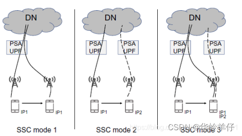
PDU session flow
Spark ShuffleManager
Microsoft Word tutorial "5", how to change the margins and create a newsletter column in word?

用一个性能提升了666倍的小案例说明在TiDB中正确使用索引的重要性
随机推荐
移动端渲染原理浅析
4.35V锂电充电IC
20192407 2021-2022-2 《网络与系统攻防技术》实验八实验报告
Fs4521 constant voltage linear charging IC
功耗开发经验分享:设计功耗大板
传音 Infinix 新机现身谷歌产品库,TECNO CAMON 19 预装 Android 13
When the college entrance examination is opened, VR panorama can see the test site in this way
网上开期货账户安全吗?如何避免被骗?
Microsoft Word tutorial "5", how to change the margins and create a newsletter column in word?
C语言 浮点数 储存形式
Unity 分析内置地形(Terrain)的渲染并做一些有意思的事情
How to use the low code platform of the Internet of things for worksheet management?
性能测试方案(计划)模板
How to stack double and float in the bottom layer of C language
Logback exclude specified package / class / method log output
HM3416H降压IC芯片PWM/PFM 控制 DC-DC 降压转换器
国庆期间给大家推荐一个可能会成为2019最佳的CRUD工具
Harbor image pull voucher configuration
【legendre】多项式
刷脸认证如何实现人脸又快又准完成校验?