当前位置:网站首页>An example of type3 voltage loop compensator taking Boost as an example
An example of type3 voltage loop compensator taking Boost as an example
2022-08-02 12:03:00 【q601785959】
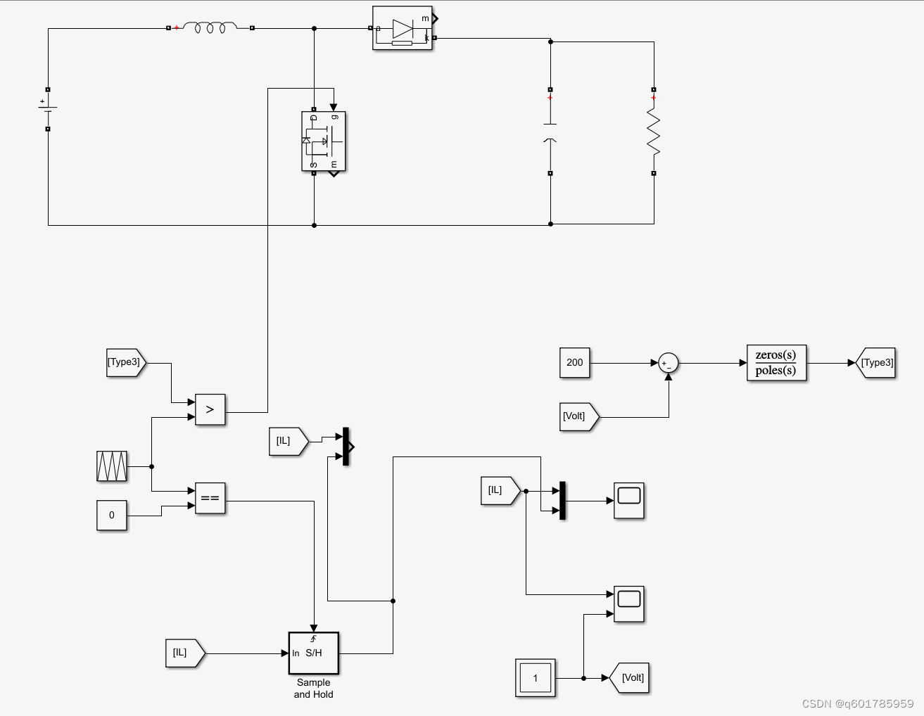
Because the zero-pole control in the switching power supply has a greater degree of freedom for the stability of the control system, I have been studying and learning the zero-pole control in the switching power supply for the past six months.It should be difficult, because the mathematical model is complex and difficult to derive and calculate. I have been flipping through the book for the past six months and still haven't fully grasped it. Fortunately, I learned that I can directly compensate through the existing model and get the parameters.record
1. Enter relevant parameters and transfer functions in the .m function
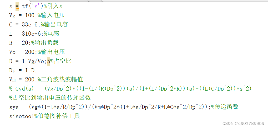
2. Run and open the sisotool tool
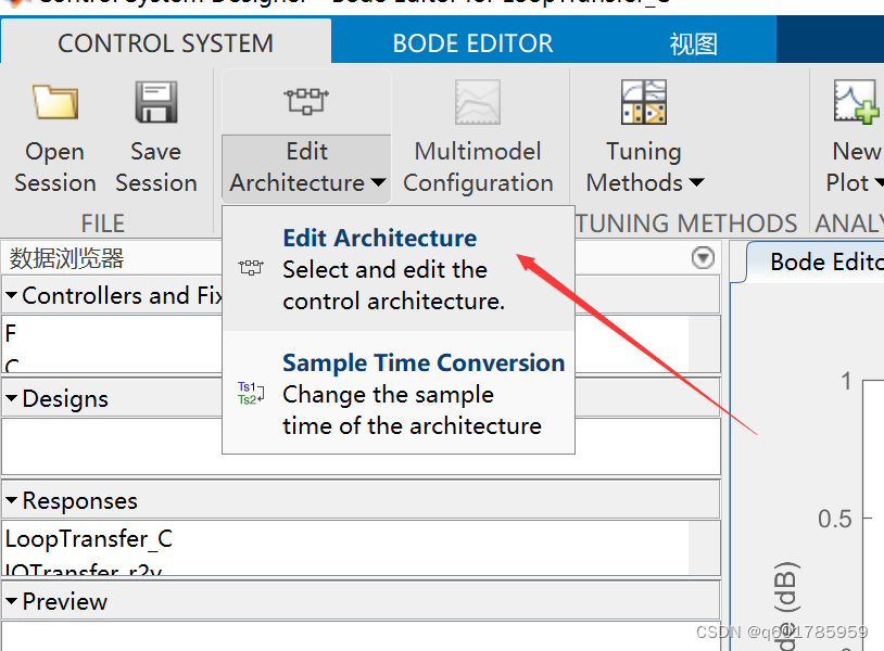
3. Select the control method and import the control object transfer function, where G is the controlled object model, C is the compensator, H is the feedback gain, and F is the setting parameter. In the example, it is assumed that the H and F gains are both 1

4. After importing the model, the Bode diagram/root locus special diagram and step response diagram of the control object are obtained as follows
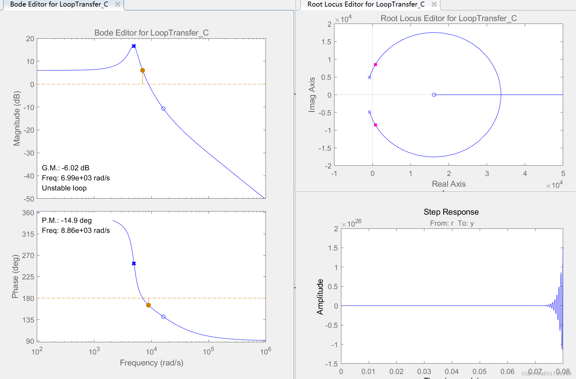
5. Add zero-pole compensation Click BODE EDITOR and add zero-pole Type3 in the s domain as 3Plose/2Zreo
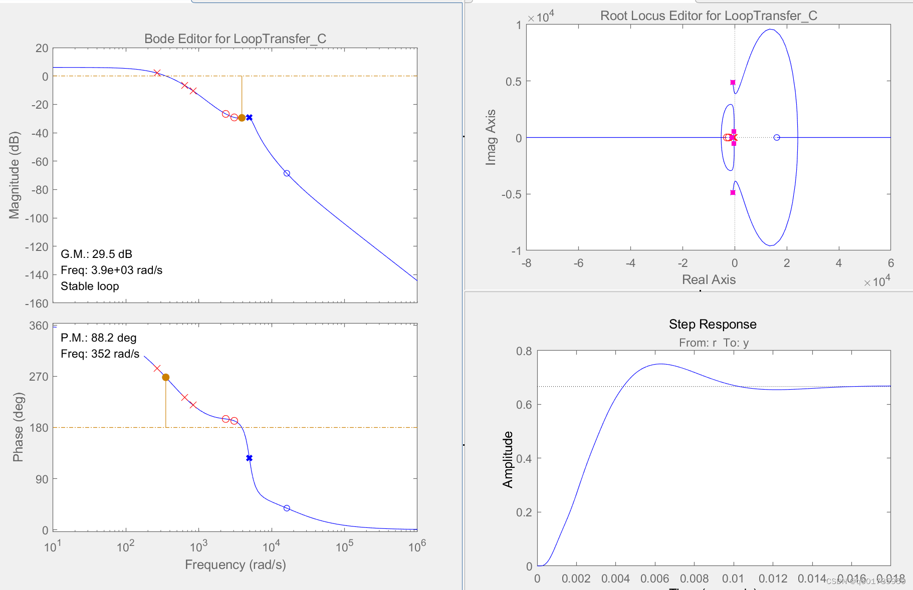
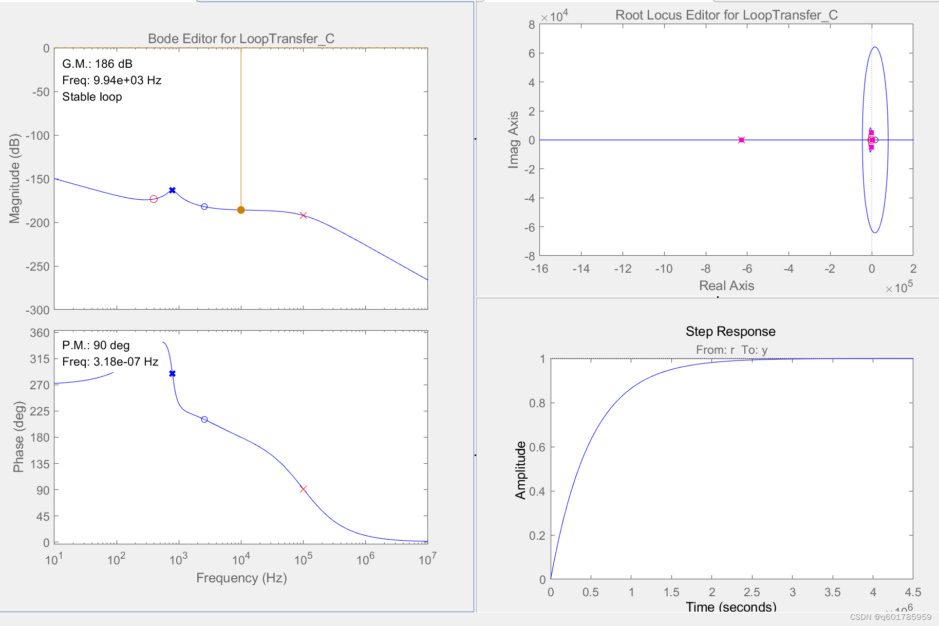
6. Double-click C on the left to design the parameters of the compensator. For example, Type3 has one original pole and two high-frequency poles. Place the high-frequency pole at the switching frequency to suppress the high-frequency interference caused by the switching frequency. 2The zero point is placed at 1/2 of the conjugate pole of the control object, and the following figure is obtained. From the figure, it can be seen that the compensated step response has no overshoot but the response rises slowly
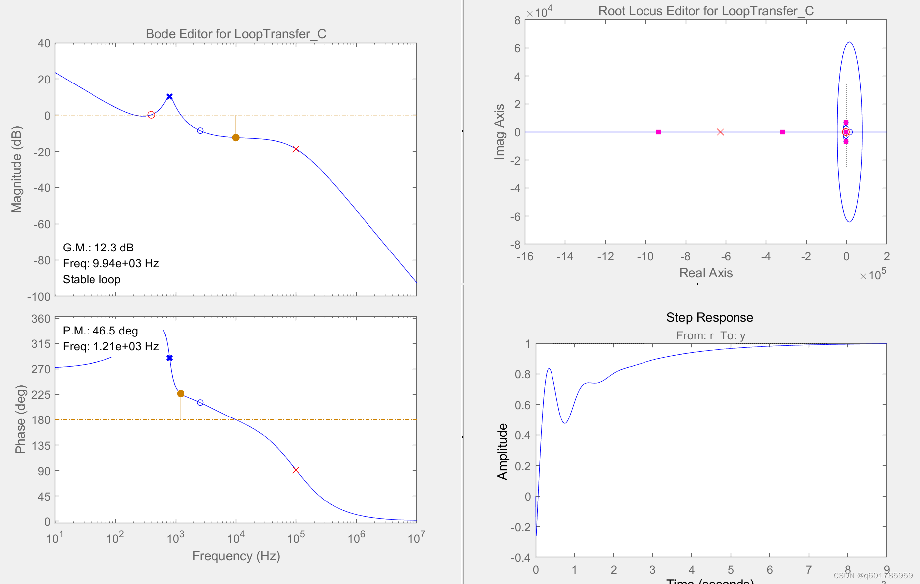
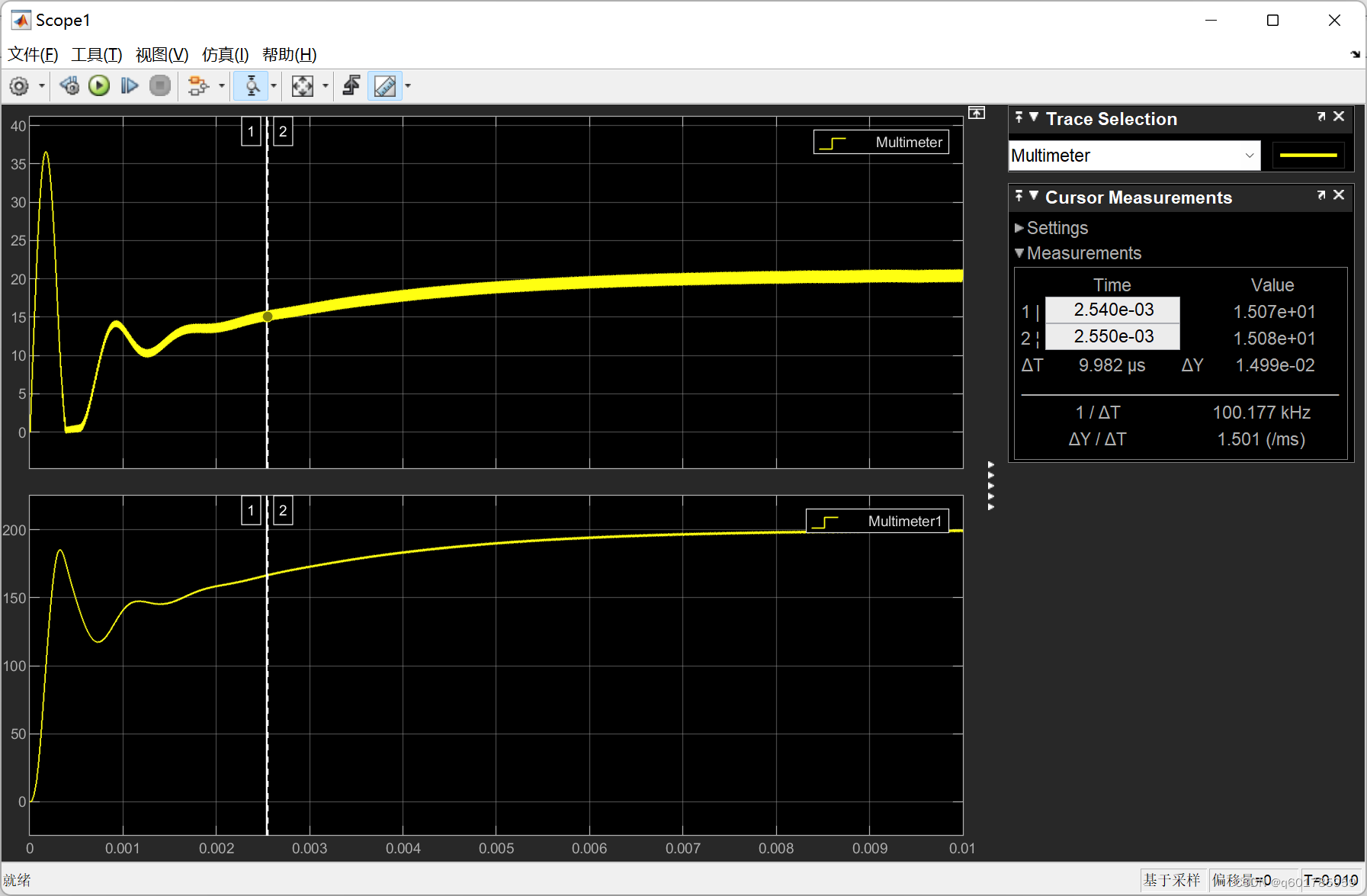
7. At this time, the phase diagram can be moved up to 0dB. Generally, the compensator requires a -20dB slope to cross the 0dB line. The final effect is shown in the figure below. The gain margin is 12.3dB and the phase margin is 46.5dB.Greater than 45dB requirements
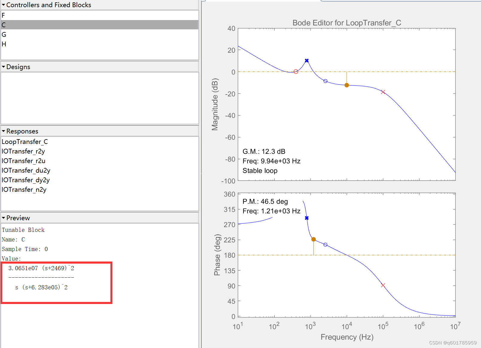
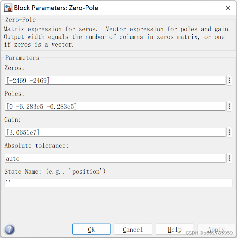
8. At this time, it can be substituted according to the compensator parameters on the right, where Gain is 3.0651e07, the two overlapping zeros are 2469, the three poles are 0 and the two overlapping poles are 6.283e05
边栏推荐
猜你喜欢
随机推荐
npm run serve启动报错npm ERR Missing script “serve“
打破千篇一律,DIY属于自己独一无二的商城
Create your own app applet ecosystem with applet containers
翻译英语的软件-免费翻译软件-各种语言互相翻译
喜迎八一 《社会企业开展应聘文职人员培训规范》团体标准出版发行会暨橄榄枝大课堂上线发布会在北京举行
Pytorch 占用cpu资源过多
SQL函数 $TRANSLATE
基于threejs的商品VR展示平台的设计与实现思路
ansible module --copy module
免费的中英文翻译软件-自动批量中英文翻译软件推荐大全
JVM简介
Metaverse "Drummer" Unity: Crazy expansion, suspense still exists
自己如何做小程序呢?
借小程序容器打造自有App小程序生态
Swift中什么时候不能用 () 代替 Void 来使用
使用kubesphere图形界面创建一个应用操作流程
解决导出excel文件名中文乱码的问题
Thymeleaf
从幻核疑似裁撤看如何保证NFT的安全
ASP.NET Core 6框架揭秘实例演示[31]:路由“高阶”用法
