当前位置:网站首页>FPGA Development (1) -- serial port communication
FPGA Development (1) -- serial port communication
2022-06-29 23:50:00 【No change of name 1】
1、RS232 Introduction to communication protocol
1、RS232 yes UART A kind of , There's no clock line , There are only two data lines , Namely rx and tx, These two wires are 1bit The seat is wide . among rx Is the line that receives data ,tx It's a line that sends data .
2、rx The seat width is 1bit,PC The machine passes the serial port debugging assistant to FPGA Hair 8bit Data time ,FPGA Through the serial port cable rx Receive... Bit by bit , Receive from the lowest bit to the highest bit , Last in FPGA The inner part is spliced into 8 Bit data .
3、tx The seat width is 1bit,FPGA Through the serial port PC Engine engine 8bit Data time ,FPGA hold 8bit Data is passed through tx The line is passed one by one to PC machine , Send from the lowest bit to the highest bit , Finally, the upper computer uses the serial port assistant to follow the instructions RS232 The protocol splices the data bits one by one into 8bit data .
4、 The sending and receiving of serial port data is based on the frame structure , I.e. sending and receiving data frame by frame . Every frame except the middle contains 8bit Valid data , There must also be a start bit at the beginning of each frame , And fixed to 0; There must also be a stop bit at the end of each frame , And fixed to 1, That is, the most basic frame structure ( Excluding calibration, etc ) Yes 10bit. Without sending or receiving data ,rx and tx At rest , here rx and tx All lines remain high , If there is data frame transmission , First there will be a start bit , And then there was 8bit Data bits of , Then there was 1bit Stop bit of , then rx and tx Continue to idle , Then wait for the next data transmission . As shown in the figure, it is the most basic RS232 Frame structure .
5、 Baud rate : In the information transmission channel , The signal unit carrying data information is called symbol ( Because the serial port is 1bit Transmitting , So the symbol represents a binary number ), The number of symbols transmitted through the signal per second is called the transmission rate of symbols , Baud rate for short , Common symbols “Baud” Express , The unit is “ Porter per second (Bps)”. The common baud rate of serial port is 4800、9600、115200 etc. , We chose to use 9600 Baud rate for the serial port chapter .
6、 Bit rate : The amount of information transmitted by the communication channel per second is called the bit transmission rate , Bit rate for short , The unit is “ Bits per second (bps)”. The bit rate can be calculated from the baud rate , Formula for : Bit rate = Baud rate * The number of bits corresponding to a single modulation state . If you are using 9600 Baud rate , The bit rate of the serial port is :9600Bps * 1bit= 9600bps.
7、 Sent or received by the calculated serial port 1bit The time of data is one baud , namely 1/9600 second , If you use 50MHz( The period is 20ns) System clock to count , The number to be counted is cnt = (1s * 10^9)ns / 9600bit)ns / 20ns ≈ 5208 Two system clock cycles , each bit The interval between the data should be 50MHz Count at the clock frequency of 5208 Time .
8、 The upper computer sends a message through the serial port 8bit Data time , Will automatically send 8 Bit valid data is preceded by a starting bit of baud time , It will also be automatically sent out 8 A stop bit is sent after the bit valid data . Empathy , Before the serial port assistant receives the data sent by the upper computer , A start bit of baud time must be detected before receiving data , After receiving 8bit After the data of , Receive another stop bit of baud time .

2、 Serial communication program design
The experiment is finished PC The client sends data through the serial port assistant ,FPGA After receiving the data, send it to PC End , The top-level module block diagram is shown in the figure below , It mainly includes two modules , They are the sending and receiving modules , Write the code of the two modules respectively for simulation verification .
The receiving module is shown in the figure below , The signal access port has a clock 、 Reset and serial data input . The data output port has serial data output and flag bit .
The sequence diagram of serial port sending module is shown in the following figure , Here we mainly refer to the tutorial of wildfire , For details, you can download the wild fire documentation .
Write our... According to the sequence diagram verilog Code , The code of the data receiving module is as follows .
module uart_rx
#(
    parameter freq = 'd50_000_000, parameter baud = 'd9600
)
(
    input clk,
    input rst_n,
    input rx,

    output reg out_flag,
    output reg [7:0] out_data
);

parameter BAUD_MAX=freq/baud;

reg rx_reg1;
reg rx_reg2;
reg rx_reg3;
reg start_flag;
reg work_en;
reg [3:0]  bit_cnt;
reg bit_flag;
reg [12:0] baud_cnt;
reg [7:0] rx_data;
reg rx_flag;

always @(posedge clk or negedge rst_n) begin
    if(~rst_n)begin
        rx_reg1<=1'b1; end else begin rx_reg1<=rx; end end always @(posedge clk or negedge rst_n) begin if(~rst_n)begin rx_reg2<=1'b1;
    end
    else begin
        rx_reg2<=rx_reg1;
    end
end

always @(posedge clk or negedge rst_n) begin
    if(~rst_n)begin
        rx_reg3<=1'b1; end else begin rx_reg3<=rx_reg2; end end always @(posedge clk or negedge rst_n) begin if(~rst_n)begin start_flag<=1'b0;
    end
    else if(rx_reg2==1'b0 && rx_reg3==1'b1 && work_en==1'b0)begin start_flag<=1'b1;
    end
    else start_flag<=1'b0; end always @(posedge clk or negedge rst_n) begin if(~rst_n)begin work_en<=1'b0;
    end
    else if(start_flag==1'b1)begin work_en<=1'b1;
    end
    else if(bit_cnt==4'd8 && bit_flag)begin work_en<=1'b0;
    end
end

always @(posedge clk or negedge rst_n) begin
    if(~rst_n)begin
      baud_cnt<=13'd0; end else if(baud_cnt == BAUD_MAX-1'b1 || work_en==1'b0)begin baud_cnt<=13'd0;
    end
    else baud_cnt<=baud_cnt+1'b1; end always @(posedge clk or negedge rst_n) begin if(~rst_n)begin bit_flag<=1'b0;
    end
    else if(baud_cnt==BAUD_MAX/2'd2-1'b1)begin
      bit_flag<=1'b1; end else bit_flag<=1'b0;
end

always @(posedge clk or negedge rst_n) begin
    if(~rst_n)begin
        bit_cnt<=4'd0; end else if(bit_flag==1'b1 & bit_cnt==4'd8)begin bit_cnt<=4'd0;
    end
    else if( bit_flag==1'b1)begin bit_cnt<=bit_cnt+1'b1;
    end
    else bit_cnt<=bit_cnt;
end

always @(posedge clk or negedge rst_n) begin
    if(~rst_n)begin
      rx_data<=8'd0; end else if(bit_flag==1'b1 && bit_cnt>=4'd1 && bit_cnt<=4'd8)begin
        rx_data<={
    rx_reg3,rx_data[7:1]};
    end
    else rx_data<=rx_data;
end

always @(posedge clk or negedge rst_n) begin
    if(~rst_n)begin
        rx_flag<=1'b0; end else if(bit_flag==1'b1 & bit_cnt==4'd8)begin rx_flag<=1'b1;
    end
    else rx_flag<=1'b0; end always @(posedge clk or negedge rst_n) begin if(~rst_n)begin out_data<=8'd0;
    end
    else if(rx_flag==1'b1)begin out_data<=rx_data; end else out_data<=out_data; end always @(posedge clk or negedge rst_n) begin if(~rst_n)begin out_flag<=1'b0;
    end
    else if(rx_flag==1'b1)begin out_flag<=rx_flag; end else out_flag<=1'b0;
end

endmodule
Write the simulation test code of the serial port receiving module as follows .
//~ `New testbench `timescale  1ns / 1ps

module tb_uart_rx;

// uart_rx Parameters
parameter PERIOD    = 10          ;
parameter freq      = 'd50_000_0; parameter baud = 'd9600      ;
parameter BAUD_MAX  = freq/baud   ;

// uart_rx Inputs
reg   clk                                  = 0 ;
reg   rst_n                                = 0 ;
reg   rx                                   = 0 ;

// uart_rx Outputs
wire  out_flag                             ;
wire  [7:0]  out_data                      ;


initial
begin
    forever #(PERIOD/2) clk=~clk;
end

initial
begin
    #(PERIOD*2) rst_n = 1;
end

uart_rx #(
    .freq     ( freq     ),
    .baud     ( baud     )
)
 u_uart_rx (
    .clk                     ( clk             ),
    .rst_n                   ( rst_n           ),
    .rx                      ( rx              ),

    .out_flag                ( out_flag        ),
    .out_data                ( out_data  [7:0] )
);

initial
begin
    #(PERIOD*10);
    rx_bit(8'd0); rx_bit(8'd1);
    rx_bit(8'd2); rx_bit(8'd3);
end

task rx_bit(
    input [7:0] data
);
integer i;

for(i=0;i<10;i=i+1)begin
  case(i)
    0:rx<=1'b0; 1:rx<=data[0]; 2:rx<=data[1]; 3:rx<=data[2]; 4:rx<=data[3]; 5:rx<=data[4]; 6:rx<=data[5]; 7:rx<=data[6]; 8:rx<=data[7]; 9:rx<=1'b1;
  endcase
    #(PERIOD*52);
end

endtask

endmodule
The final simulation results are shown in the figure below , It can be seen that the simulation result receiving module receives 8 Bit serial data , After receiving a byte , Output a flag bit signal and 8 Bit length data .
Next is the sending module , The sending module mainly includes a clock 、 Reset 、 Input parallel data 、 Sign a 、 Serial data output .
The sequence diagram is shown in the figure below , For specific code explanation, please refer to the wildfire document .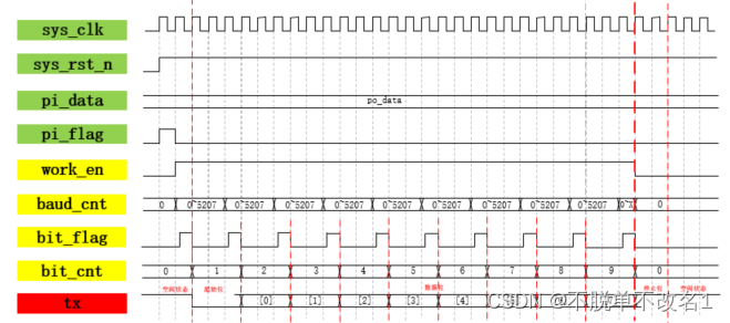
The code of serial port sending module is shown in the figure below .
module uart_tx
#(
    parameter freq = 'd50_000_000, parameter baud = 'd9600
)
(
    input clk,
    input rst_n,
    input [7:0] in_data,
    input in_flag,

     output reg tx
);

parameter BAUD_MAX=freq/baud;

reg work_en;
reg bit_flag;
reg [3:0] bit_cnt;
reg [12:0] baud_cnt;

always @(posedge clk or negedge rst_n) begin
    if(~rst_n)begin
        work_en<=1'b0; end else if(in_flag==1'b1)begin
      work_en<=1'b1; end else if(bit_cnt==4'd9 && bit_flag==1'b1)begin work_en<=1'b0;
    end
end

always @(posedge clk or negedge rst_n) begin
    if(~rst_n)begin
      baud_cnt<=13'd0; end else if(baud_cnt == BAUD_MAX-1'b1 || work_en==1'b0)begin baud_cnt<=13'd0;
    end
    else baud_cnt<=baud_cnt+1'b1; end always @(posedge clk or negedge rst_n) begin if(~rst_n)begin bit_flag<=1'b0;
    end
    else if(baud_cnt==13'd1)begin bit_flag<=1'b1;
    end
    else bit_flag<=1'b0; end always @(posedge clk or negedge rst_n) begin if(~rst_n)begin bit_cnt<=4'd0;
    end
    else if(bit_cnt==4'd9 && bit_flag==1'b1)begin
      bit_cnt<=4'd0; end else if(bit_flag==1'b1)begin
      bit_cnt<=bit_cnt+1'b1; end else bit_cnt<=bit_cnt; end always @(posedge clk or negedge rst_n) begin if(~rst_n)begin tx<=1'b1;
    end
    else if(bit_flag==1'b1)begin case(bit_cnt) 4'd0:tx<=1'b0; 4'd1:tx<=in_data[0];
        4'd2:tx<=in_data[1]; 4'd3:tx<=in_data[2];
        4'd4:tx<=in_data[3]; 4'd5:tx<=in_data[4];
        4'd6:tx<=in_data[5]; 4'd7:tx<=in_data[6];
        4'd8:tx<=in_data[7]; 4'd9:tx<=1'b1; default:tx<=1'b1;
      endcase
    end
end

endmodule
The test code of the serial port sending module is shown in the figure below .
`timescale  1ns / 1ps

module tb_uart_tx;

// uart_tx Parameters
parameter PERIOD    = 10          ;
parameter freq      = 'd50_000_0; parameter baud = 'd9600      ;
parameter BAUD_MAX  = freq/baud   ;

// uart_tx Inputs
reg   clk                                  = 0 ;
reg   rst_n                                = 0 ;
reg   [7:0]  in_data                       = 0 ;
reg   in_flag                              = 0 ;

// uart_tx Outputs
wire  tx                                   ;


initial
begin
    forever #(PERIOD/2) clk=~clk;
end

initial
begin
    #(PERIOD*2) rst_n = 1;
end

uart_tx #(
    .freq     ( freq     ),
    .baud     ( baud     ))
 u_uart_tx (
    .clk                     ( clk            ),
    .rst_n                   ( rst_n          ),
    .in_data                 ( in_data  [7:0] ),
    .in_flag                 ( in_flag        ),

    .tx                      ( tx             )
);

initial
begin
     in_data<=8'd0; in_flag<=1'b0;
     #(PERIOD*10)

     in_data<=8'd0; in_flag<=1'b1;
     #(PERIOD)
     in_flag<=1'b0; #(PERIOD*52*10) in_data<=8'd1;
     in_flag<=1'b1; #(PERIOD) in_flag<=1'b0;
     #(PERIOD*52*10)

     in_data<=8'd2; in_flag<=1'b1;
     #(PERIOD)
     in_flag<=1'b0; #(PERIOD*52*10) in_data<=8'd3;
     in_flag<=1'b1; #(PERIOD) in_flag<=1'b0;

end

endmodule
The simulation diagram of serial port sending module is shown in the following figure , It can be seen that the sending module converts the data into serial data after receiving the parallel data and flag bits tx Port send back PC port .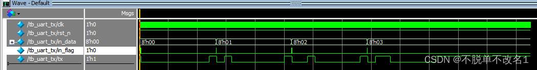
3、 On board verification
Here, open the serial port assistant , Set No. baud rate 、 Data bits 、 Open the serial port after the stop bit and other parameters . After sending data, you can see from the above screen FPGA The data sent back by the client , Serial communication succeeded .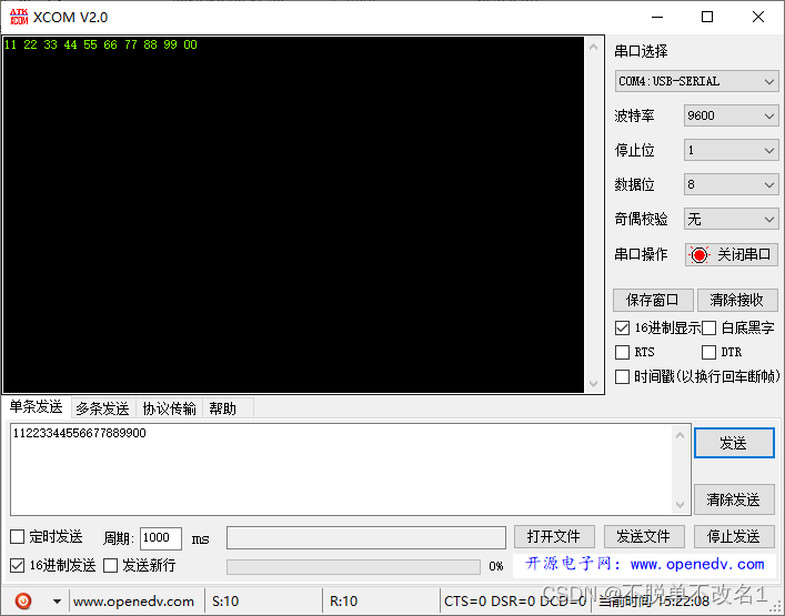
边栏推荐
- Solr basic operation
- Set up security groups, record domain names, and apply for SSL certificates
- 小程序插件接入、开发与注意事项
- label問題排查:打不開標注好的圖像
- 6.28 problem solving
- Under the epidemic, I left my job for a year, and my income increased 10 times
- Shell positional parameter variables and predefined variables
- Bee common configuration
- 【微信小程序】认识小程序项目的基本组成结构
- 6.29日刷题题解
猜你喜欢

C pointer advanced 2-- > function pointer array callback function simplifies calculator code, and implements qsort function based on callback function simulation

Gracefully transform the SMS business module and start the strategic mode!

设置安全组、域名备案、申请ssl证书

Overseas digital authentication service provider advance AI was selected into the "2022 brand sea Service Market Research Report" of equalocean

matlab习题 —— 程序控制流程练习

數莓派 4怎麼樣?可能的玩法有哪些?

剑指 Offer 13. 机器人的运动范围

matplotlib matplotlib可视化之柱状图plt.bar()

Sword finger offer 15 Number of 1 in binary

按头安利!好看又实用的电机 SolidWorks模型素材看这里
随机推荐
動態代理的實現原理
网上开户选哪个证券公司?还有,在线开户安全么?
软件测试 接口测试 Jmeter 5.5 安装教程
我想知道今天还可以开户么?另外想问,现在在线开户安全么?
按头安利 好看又实用的点胶机 SolidWorks模型素材看这里
Why is JSX syntax so popular?
I wonder if I can open an account today? In addition, is it safe to open an account online now?
Pytest initializing and cleaning up the environment
Sword finger offer 38 Arrangement of strings
小程序插件接入、开发与注意事项
FPGA开发(2)——IIC通信
为什么 JSX 语法这么香?
Gracefully transform the SMS business module and start the strategic mode!
C pointer advanced 1-- > character pointer, array pointer, pointer and array parameter transfer, function pointer
Start harvesting! Nailing: adjust the maximum number of free users of "nailing team". If the number exceeds 10, it will not work normally
Implementation of aut, a self-developed transport layer protocol for sound network -- dev for dev column
Label Troubleshooting: unable to open the marked image
Leetcode 1385. Distance value between two arrays
Solr基础操作
shell-运算符