当前位置:网站首页>URDF syntax explanation
URDF syntax explanation
2022-07-26 03:16:00 【2021 Nqq】
List of articles
Simple example
stay Rviz A box shaped robot is shown in
URDF file demo01_helloworld.urdf
<robot name="mycar">
    <link name="base_link">
        <visual>
            <geometry>
                <box size="0.5 0.2 0.1" />
            </geometry>
        </visual>
    </link>
</robot>
launch file demo01_helloworld.launch
<launch>
    <!-- 1.  Load in the parameter server  urdf  file ; name The value is fixed -->
    <param name = "robot_description" textfile = "$(find urdf01_rviz)/urdf/urdf/demo01_helloworld.urdf" />
    <!-- 2.  start-up  rviz args For preservation rviz file -->
    <node pkg = "rviz" type = "rviz" name = "rviz" args = "-d $(find urdf01_rviz)/config/show_mycar.rviz"/>
</launch>
source ./devel/setup.bash
roslaunch urdf01_rviz demo01_helloworld.launch
link
Definition :urdf Medium link The label is used to describe a part of the robot ( That is, the rigid body part ) The appearance and physical properties of , such as : Robot base 、 wheel 、 Laser radar 、 camera … Each part corresponds to a link, stay link tag , You can design the shape of the part 、 Size 、 Color 、 Inertia matrix 、 Collision parameters and other attributes .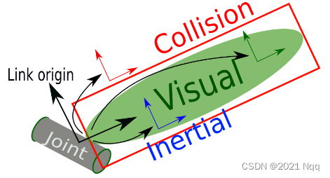
- Inertial: Inertia matrix
- Collision: Collision parameters
- Visual: visualization

URDF file demo02_link.urdf
<!--  demand :  Set robot parts with different shapes  -->
<robot name = "mycar">
    <link name = "base_link">
        <!--  Visual tags  -->
        <visual>
            <!-- 1.  shape  -->
            <geometry>
                <!-- 1.1  Cube  x,y,z-->
                <!-- <box size = "0.3 0.2 0.1" /> -->
                <!-- 1.2  Cylinder  -->
                <!-- <cylinder radius = "0.1" length = "2" /> -->
                <!-- 1.3  sphere  -->
                <!-- <sphere radius = "1" /> -->
                <!-- 1.4  The skin  -->
                <mesh filename = "package://urdf01_rviz/meshes/autolabor_mini.stl"/>
            </geometry>

            <!-- 2.  Offset and tilt radian  -->
            <!-- xyz  Set up the robot model in  x, y, z Offset on axis  rpy  Set the tilt radian  x( Roll ) y( pitch ) z( Yaw ) -->
            <origin xyz = "0 0 0" rpy = "1.57 0 1.57" />

            <!-- 3.  Color  -->
            <!-- rgba: r = red g = green b = blue a =  transparency   The four values are between [0,1] -->
            <material name = "car_color">
                <color rgba = "0 1 0 1" />
            </material>
        </visual>
    </link>
</robot>
launch file demo02_link.launch
<launch>
    <!-- 1.  Load in the parameter server  urdf  file ; name The value is fixed -->
    <param name = "robot_description" textfile = "$(find urdf01_rviz)/urdf/urdf/demo02_link.urdf" />
    <!-- 2.  start-up  rviz args For preservation rviz file -->
    <node pkg = "rviz" type = "rviz" name = "rviz" args = "-d $(find urdf01_rviz)/config/show_mycar.rviz"/>
</launch>
joint
urdf Medium joint Tags are used to describe the kinematic and dynamic properties of robot joints , You can also specify the safety limit of joint movement , Two parts of the robot ( They are called respectively parent link And child link) With " The joints " Connected in the form of , Different joints have different forms of motion : rotate 、 slide 、 Fix 、 Rotation speed 、 Rotation angle limit …, such as : Wheels mounted on the base can 360 Degree of rotation , The camera may be completely fixed on the base .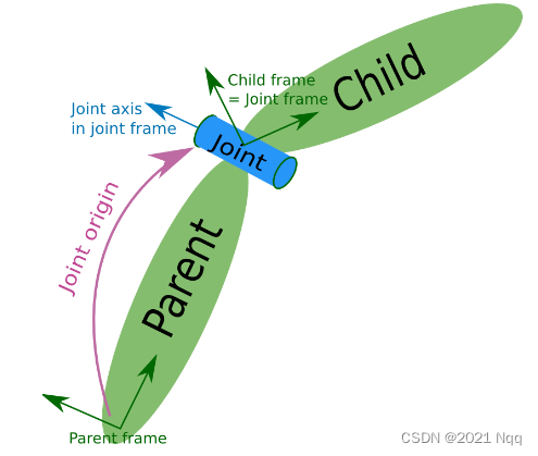


origin Namely The purple part above ,joint About parent_link Location relationship of

URDF file demo03_joint.urdf
urdf Using Chinese Notes in the document may report errors
<!--  demand :  Set up the robot chassis , And add a camera  -->
<robot name = "mycar">
    <!-- 1.  chassis link -->
    <link name = "base_link">
        <visual>
            <geometry>
                <box size = "0.3 0.2 0.1" />
            </geometry>
            <origin xyz = "0 0 0" rpy = "0 0 0" />
            <material name = "car_color">
                <color rgba = "0.8 0.5 0 0.5" />
            </material>
        </visual>
    </link>
    <!-- 2.  camera link -->
     <link name = "camera">
        <visual>
            <geometry>
                <box size = "0.02 0.05 0.05" />
            </geometry>
            <!--  First use the default ( It needs to be modified later ) -->
            <origin xyz = "0 0 0" rpy = "0 0 0" />
            <material name = "camera_color">
                <color rgba = "0 0 1 0.5" />
            </material>
        </visual>
    </link>
    <!-- 3.  The joints -->
    <joint name = "camera2base" type = "continuous">
        <!--  Father's Day  link -->
        <parent link = "base_link" />
        <!--  Sub stanza  link -->
        <child link = "camera" />
        <!--  Set up joint Offset from parent section  -->
        <origin xyz = "0.12 0 0.05" rpy = "0 0 0" />
        <!--  Set the coordinate axis of the joint rotation reference ,0 Indicates that it will not rotate around this axis ,1 Indicates rotation around this axis  -->
        <axis xyz = "0 0 1" />
    </joint>
</robot>
launch file demo03_joint.launch
<launch>
    <!-- 1.  Load in the parameter server  urdf  file ; name The value is fixed -->
    <param name = "robot_description" textfile = "$(find urdf01_rviz)/urdf/urdf/demo03_joint.urdf" />
    <!-- 2.  start-up  rviz args For preservation rviz file -->
    <node pkg = "rviz" type = "rviz" name = "rviz" args = "-d $(find urdf01_rviz)/config/show_mycar.rviz"/>
    <!--  Only the above two statements :  performance :  Set the display position and color of the header to be abnormal   Tips : No transform from [camera] to [base_link]  The lack of  camera  To  base_link  Coordinate transformation of   reason : rviz  Show  URDF  when , It is necessary to publish   Coordinate system   Relationship   solve : ROS It provides nodes related to the coordinate publishing of robot model display ( Two ) rosrun joint_state_publisher joint_state_publisher rosrun robot_state_publisher robot_state_publisher -->
    <!--  Joint status publishing node  -->
    <node pkg = "joint_state_publisher" type = "joint_state_publisher" name = "joint_state_publisher" />
    <!--  Robot status publishing node  -->
    <node pkg = "robot_state_publisher" type = "robot_state_publisher" name = "robot_state_publisher" />

</launch>
Optimize
URDF file demo04_base_footprint.urdf
<!--  demand :  Set up the robot chassis , And add a camera  -->
<robot name = "mycar">
    <!--  Add a very small joint  link,  Then go to the associated time  link  And  base_link,  The height of the joint is just the same as  base_link  The sinking height is the same ( Half the chassis height ) -->
    <link name = "base_footprint">
        <visual>
            <geometry>
                <box size = "0.001 0.001 0.001" />
            </geometry>
        </visual>
    </link>

    <!-- 1.  chassis link -->
    <link name = "base_link">
        <visual>
            <geometry>
                <box size = "0.3 0.2 0.1" />
            </geometry>
            <origin xyz = "0 0 0" rpy = "0 0 0" />
            <material name = "car_color">
                <color rgba = "0.8 0.5 0 0.5" />
            </material>
        </visual>
    </link>

    <!-- 2.  camera link -->
     <link name = "camera">
        <visual>
            <geometry>
                <box size = "0.02 0.05 0.05" />
            </geometry>
            <!--  First use the default ( It needs to be modified later )  By default, the joint coincides with the center point of the connecting rod -->
            <origin xyz = "0 0 0.025" rpy = "0 0 0" />
            <material name = "camera_color">
                <color rgba = "0 0 1 0.5" />
            </material>
        </visual>
    </link>

    <!--  relation  base_footprint  And  base_link -->
    <joint name = "link2footprint" type = "fixed">
        <!--  Father's Day  link -->
        <parent link = "base_footprint" />
        <!--  Sub stanza  link -->
        <child link = "base_link" />
        <!--  Set the offset of the child section from the parent section  z For half base_link Height -->
        <origin xyz = "0 0 0.05" rpy = "0 0 0" />
    </joint>

    <!-- 3.  The joints -->
    <joint name = "camera2base" type = "continuous">
        <!--  Father's Day  link -->
        <parent link = "base_link" />
        <!--  Sub stanza  link -->
        <child link = "camera" />
        <!--  Set the offset of the child section from the parent section  -->
        <origin xyz = "0.12 0 0.05" rpy = "0 0 0" />
        <!--  Set the coordinate axis of the joint rotation reference ,0 Indicates that it will not rotate around this axis ,1 Indicates rotation around this axis  -->
        <axis xyz = "0 0 1" />
    </joint>
</robot>
launch file demo04_base_footprint.launch
<launch>
    <!-- 1.  Load in the parameter server  urdf  file ; name The value is fixed -->
    <param name = "robot_description" textfile = "$(find urdf01_rviz)/urdf/urdf/demo04_base_footprint.urdf" />
    <!-- 2.  start-up  rviz args For preservation rviz file  -->
    <node pkg = "rviz" type = "rviz" name = "rviz" args = "-d $(find urdf01_rviz)/config/show_mycar.rviz"/>
    <!--  Only the above two statements :  performance :  Set the display position and color of the header to be abnormal   Tips : No transform from [camera] to [base_link]  The lack of  camera  To  base_link  Coordinate transformation of   reason : rviz  Show  URDF  when , It is necessary to publish   Coordinate system   Relationship   solve : ROS It provides nodes related to the coordinate publishing of robot model display ( Two ) rosrun joint_state_publisher joint_state_publisher rosrun robot_state_publisher robot_state_publisher -->
    <!--  Joint status publishing node  -->
    <node pkg = "joint_state_publisher" type = "joint_state_publisher" name = "joint_state_publisher" />
    <!--  Robot status publishing node  -->
    <node pkg = "robot_state_publisher" type = "robot_state_publisher" name = "robot_state_publisher" />
</launch>
practice
link The offset is the offset between the center of the object and the origin of the geodetic coordinate system
joint The offset is two link The offset between coordinate systems
The design requirements : Create a four wheeled cylindrical robot model , The robot parameters are as follows , The chassis is cylindrical , radius 10cm, high 8cm, The four wheels are composed of two driving wheels and two universal support wheels , The radius of the two driving wheels is 3.25cm, Tire width 1.5cm, The two universal wheels are spherical , radius 0.75cm, The distance between the chassis and the ground is 1.5cm( Consistent with the diameter of universal wheel )
launch file
<launch>
    <!-- 1.  Load in the parameter server URDF -->
    <param name = "robot_description" textfile = "$(find urdf01_rviz)/urdf/urdf/demo05_test.urdf" />

    <!-- 2.  start-up rviz -->
    <node pkg = "rviz" type = "rviz" name = "rviz" args = "-d $(find urdf01_rviz)/config/show_mycar.rviz"/>

    <!-- 3.  Add joint status publishing node  -->
    <node pkg = "joint_state_publisher" type = "joint_state_publisher" name = "joint_state_publisher" />

    <!-- 4.  Add robot status publishing node  -->
    <node pkg = "robot_state_publisher" type = "robot_state_publisher" name = "robot_state_publisher" />

    <!-- 5.  Joint motion control node  -->
    <node pkg = "joint_state_publisher_gui" type = "joint_state_publisher_gui" name = "joint_state_publisher_gui" />

</launch>
Add a tiny sphere
 <!-- 1.  add to  base_footprint  Just a tiny sphere or cube -->
    <link name = "base_footprint">
        <visual>
            <geometry>
                <sphere radius = "0.001" />
            </geometry>
            <material name = "car_color">
                <color rgba = "1 0 0 0.5" />
            </material>
        </visual>
    </link>
Add chassis
<!-- 2.  Add chassis  -->
    <!--  shape :  The chassis is cylindrical , radius  0.1m, high  0.08m  Distance from the ground : 0.015m -->
    <!-- 2-1 link -->
    <link name = "base_link">
        <visual>
            <geometry>
                <cylinder radius = "0.1" length = "0.08" />
            </geometry>
            <origin xyz = "0 0 0" rpy = "0 0 0"/>
            <material name = "baselink_color">
                <color rgba = "1 0.5 0.2 0.5" />
            </material>
        </visual>
    </link>
    <!-- 2-2 joint  Height of half car body 0.08m/2+0.015m-->
    <joint name = "link2footprint" type = "fixed">
        <parent link = "base_footprint" />
        <child link = "base_link" />
        <!--  The joints z Settings on  =  Height of car body /2 +  Height above ground  -->
        <origin xyz = "0 0 0.055" rpy = "0 0 0" />
    </joint>
Add drive wheels
The driving wheel shakes during debugging , Because I opened two joint_state_publisher, One is static , One is dynamic , cause tf Conflict
 <!-- 4.  Add Cardan wheel  -->
    <!--  shape :  The ball   radius : 0.0075m -->
    <!-- 4-1 link -->
    <link name = "front_wheel">
        <visual>
            <geometry>
                <sphere radius = "0.0075" />
            </geometry>
            <origin xyz = "0 0 0" rpy = "0 0 0"/>
            <material name = "wheel_color">
                <color rbga = "0 0 0 0.3" />
            </material>
        </visual>
    </link>
    <link name = "back_wheel">
        <visual>
            <geometry>
                <sphere radius = "0.0075" />
            </geometry>
            <origin xyz = "0 0 0" rpy = "0 0 0"/>
            <material name = "wheel_color">
                <color rbga = "0 0 0 0.3" />
            </material>
        </visual>
    </link>
    <!-- 4-2 joint -->
    <joint name = "front2link" type = "continuous">
        <parent link = "base_link" />
        <child link = "front_wheel" />
        <!-- x: 0.08  Less than the radius  y: 0 z: 0.04 + 0.015 - 0.0075 = 0.0475 -->
        <origin xyz = "0.08 0 -0.0475" rpy = "0 0 0" />
        <!--  Rotate around Y Axis  -->
        <axis xyz = "0 1 0" />
    </joint>
       <joint name = "back2link" type = "continuous">
        <parent link = "base_link" />
        <child link = "back_wheel" />
        <!-- x: 0.08  Less than the radius  y: 0 z: 0.04 + 0.015 - 0.0075 = 0.0475 -->
        <origin xyz = "-0.08 0 -0.0475" rpy = "0 0 0" />
        <!--  Rotate around Y Axis  -->
        <axis xyz = "0 1 0" />
    </joint>
URDF Tools
Open in the terminal urdf Folder
check_urdf demo05_test.urdf
urdf_to_graphiz demo05_test.urdf , The following appears
Created file mycar.gv
Created file mycar.pdf
evince mycar.pdf
urdf General procedure demo05_test.urdf
<robot name = "mycar">
    <!-- 1.  add to  base_footprint  Just a tiny sphere or cube -->
    <link name = "base_footprint">
        <visual>
            <geometry>
                <sphere radius = "0.001" />
            </geometry>
            <material name = "car_color">
                <color rgba = "1 0 0 0.5" />
            </material>
        </visual>
    </link>

    <!-- 2.  Add chassis  -->
    <!--  shape :  The chassis is cylindrical , radius  0.1m, high  0.08m  Distance from the ground : 0.015m -->
    <!-- 2-1 link -->
    <link name = "base_link">
        <visual>
            <geometry>
                <cylinder radius = "0.1" length = "0.08" />
            </geometry>
            <origin xyz = "0 0 0" rpy = "0 0 0"/>
            <material name = "baselink_color">
                <color rgba = "1 0.5 0.2 0.5" />
            </material>
        </visual>
    </link>
    <!-- 2-2 joint  Height of half car body 0.08m/2+0.015m-->
    <joint name = "link2footprint" type = "fixed">
        <parent link = "base_footprint" />
        <child link = "base_link" />
        <!--  The joints z Settings on  =  Height of car body /2 +  Height above ground  -->
        <origin xyz = "0 0 0.055" rpy = "0 0 0" />
    </joint>

    <!-- 3.  Add drive wheels  -->
    <!--  shape :  Cylinder   radius : 0.0325m  length : 0.015m -->
    <!-- 3-1 link -->
    <link name = "left_wheel">
        <visual>
            <geometry>
                <cylinder radius = "0.0325" length = "0.015" />
            </geometry>
            <!--  Under normal circumstances, the cylinder face up , Here the drive wheels are on the left and right , Euler angle needs to be modified , Along the x Shaft rollover 90 degree , about 1.57 radian  -->
            <origin xyz = "0 0 0" rpy = "1.5708 0 0"/>
            <material name = "wheel_color">
                <color rgba = "0 0 0 0.3" />
            </material>
        </visual>
    </link>
    <link name = "right_wheel">
        <visual>
            <geometry>
                <cylinder radius = "0.0325" length = "0.015" />
            </geometry>
            <!--  Under normal circumstances, the cylinder face up , Here the drive wheels are on the left and right , Euler angle needs to be modified , Along the x Shaft rollover 90 degree , about 1.57 radian  -->
            <origin xyz = "0 0 0" rpy = "1.5708 0 0"/>
            <material name = "wheel_color">
                <color rgba = "0 0 0 0.3" />
            </material>
        </visual>
    </link>
    <!-- 3-2 joint  Left joint  -->
    <joint name = "lest2link" type = "continuous">
        <parent link = "base_link" />
        <child link = "left_wheel" />
        <!-- x: 0  No offset  y: 0.1  Body radius  z: 0.04 + 0.015 - 0.0325 = 0.055 - 0.0325 = 0.0225, Negative numbers below   Height of car body  / 2 +  Distance from the ground  -  Wheel radius  -->
        <origin xyz = "0 0.1 -0.0225" rpy = "0 0 0" />
        <!--  Rotate around Y Axis  -->
        <axis xyz = "0 1 0" />
    </joint>
    <!-- 3-2 joint  Left joint  -->
    <joint name = "right2link" type = "continuous">
        <parent link = "base_link" />
        <child link = "right_wheel" />
        <!-- x: 0  No offset  y: 0.1  Body radius , This is going to be negative  z: 0.04 + 0.015 - 0.0325 = 0.055 - 0.0325 = 0.0225, Negative numbers below   Height of car body  / 2 +  Distance from the ground  -  Wheel radius  -->
        <origin xyz = "0 -0.1 -0.0225" rpy = "0 0 0" />
        <!--  Rotate around Y Axis  -->
        <axis xyz = "0 1 0" />
    </joint>


    <!-- 4.  Add Cardan wheel  -->
    <!--  shape :  The ball   radius : 0.0075m -->
    <!-- 4-1 link -->
    <link name = "front_wheel">
        <visual>
            <geometry>
                <sphere radius = "0.0075" />
            </geometry>
            <origin xyz = "0 0 0" rpy = "0 0 0"/>
            <material name = "wheel_color">
                <color rbga = "0 0 0 0.3" />
            </material>
        </visual>
    </link>
    <link name = "back_wheel">
        <visual>
            <geometry>
                <sphere radius = "0.0075" />
            </geometry>
            <origin xyz = "0 0 0" rpy = "0 0 0"/>
            <material name = "wheel_color">
                <color rbga = "0 0 0 0.3" />
            </material>
        </visual>
    </link>
    <!-- 4-2 joint -->
    <joint name = "front2link" type = "continuous">
        <parent link = "base_link" />
        <child link = "front_wheel" />
        <!-- x: 0.08  Less than the radius  y: 0 z: 0.04 + 0.015 - 0.0075 = 0.0475 -->
        <origin xyz = "0.08 0 -0.0475" rpy = "0 0 0" />
        <!--  Rotate around Y Axis  -->
        <axis xyz = "0 1 0" />
    </joint>
       <joint name = "back2link" type = "continuous">
        <parent link = "base_link" />
        <child link = "back_wheel" />
        <!-- x: 0.08  Less than the radius 0.1 y: 0 z: 0.04 + 0.015 - 0.0075 = 0.0475 -->
        <origin xyz = "-0.08 0 -0.0475" rpy = "0 0 0" />
        <!--  Rotate around Y Axis  -->
        <axis xyz = "0 1 0" />
    </joint>
</robot>
边栏推荐
- QT笔记——Q_Q 和Q_D 学习
- Opening method of win11 microphone permission
- Canvas -- draw text -- modification of pie chart
- Golang log programming system
- Is the galaxy VIP account opened by qiniu safe?
- 堆内存与栈内存的区别?
- Dominate the salary list! What industry has a "money" path?
- hello world驱动(二)-初级版
- The difference between the world wide web, the Internet and the Internet
- Looking at the next step of BAIC bluevale through the 8billion fund-raising, product upgrading and building core capabilities are the key words
猜你喜欢

ES6 set and map
ue4如何进行静态渲染?5个步骤生成静态渲染

Configuration and use of virtualservice, gateway and destinationrule of istio III

YOLOv3: An Incremental Improvement

canvas——绘制文本——饼图的修改
![[sql] case expression](/img/05/1bbb0b5099443f7ce5f5511703477e.png)
[sql] case expression

Oxycon 2022 network capture frontier conference is about to open!

图解LeetCode——5. 最长回文子串(难度:中等)

爆肝出了4W字的Redis面试教程

Digital commerce cloud DMS dealer management system solution: DMS system realizes business Omni channel and sales data collection
随机推荐
Managing databases in a hybrid cloud: eight key considerations
Type the URL to the web page display. What happened during this period?
Cloud native guide what is cloud native infrastructure
Canvas -- draw text -- modification of pie chart
了解预加载和懒加载、学会缓动动画
ES6 set and map
Swin Transformer【Backbone】
经典面试问题——OOP语言的三大特征
els 修改光标、修改图标
2020 AF-RCNN: An anchor-free convolutional neural network for multi-categoriesagricultural pest det
ENVI_ Idl: create HDF5 file and write data (take writing GeoTIFF file to HDF file as an example) + detailed parsing
78. 子集
Opencv saves pictures in the specified format
Chen Yili, China Academy of communications technology: cost reduction and efficiency increase are the greatest value of Enterprise Cloud native applications
QT笔记——Q_Q 和Q_D 学习
Unity quickly builds urban scenes
Unity快速搭建城市场景
What are the methods of array sorting in JS
STM32——PWM学习笔记
ELS initialization window class