当前位置:网站首页>STM32F103 - two circuit PWM control motor
STM32F103 - two circuit PWM control motor
2022-07-02 02:03:00 【SummerLoverQy】
experimental condition
STM32F103 Development board
TB6612 Motor drive module
Reference code :
#include "car.h"
// Initialize the timer , Realization PWM Output
void PWM_Init(u16 arr,u16 psc){
		GPIO_InitTypeDef GPIO_InitStructure;
		TIM_TimeBaseInitTypeDef TIM_TimeBaseStructure;
		TIM_OCInitTypeDef TIM_OCInitStructure;
		RCC_APB1PeriphClockCmd(RCC_APB1Periph_TIM3, ENABLE); //① Enable timer  3  The clock
		RCC_APB2PeriphClockCmd(RCC_APB2Periph_GPIOC|RCC_APB2Periph_AFIO, ENABLE); //① Can make  GPIO  and  AFIO  Multiplexing function clock
		GPIO_PinRemapConfig(GPIO_FullRemap_TIM3, ENABLE); //② Remap  TIM3_CH2->PB5
		// Set this pin to multiplex output function , Output  TIM3 CH2  Of  PWM  Pulse shape  GPIOB.5
		GPIO_InitStructure.GPIO_Pin = GPIO_Pin_6|GPIO_Pin_7; //TIM_CH2
		GPIO_InitStructure.GPIO_Mode = GPIO_Mode_AF_PP; // Multiplexing push pull output
		GPIO_InitStructure.GPIO_Speed = GPIO_Speed_50MHz;
		GPIO_Init(GPIOC, &GPIO_InitStructure); //① initialization  GPIO
		// initialization  TIM3
		TIM_TimeBaseStructure.TIM_Period = arr; // Set at auto reload cycle value
		TIM_TimeBaseStructure.TIM_Prescaler =psc; // Set the prescaler value
		TIM_TimeBaseStructure.TIM_ClockDivision = 0; // Set the clock split :TDTS = Tck_tim
		TIM_TimeBaseStructure.TIM_CounterMode = TIM_CounterMode_Up; //TIM  Upcount mode
		TIM_TimeBaseInit(TIM3, &TIM_TimeBaseStructure); //③ initialization  TIMx
		// initialization  TIM3 Channel2 PWM  Pattern
		TIM_OCInitStructure.TIM_OCMode = TIM_OCMode_PWM2; // choice  PWM  Pattern  2
		TIM_OCInitStructure.TIM_OutputState = TIM_OutputState_Enable; // Compare output enable
		TIM_OCInitStructure.TIM_OCPolarity = TIM_OCPolarity_High; // High output polarity
		TIM_OC1Init(TIM3, &TIM_OCInitStructure); //④ Initialize peripherals  TIM3 OC2
		TIM_OC1PreloadConfig(TIM3, TIM_OCPreload_Enable); // Enable preload register
		TIM_OC2Init(TIM3, &TIM_OCInitStructure); //④ Initialize peripherals  TIM3 OC2
		TIM_OC2PreloadConfig(TIM3, TIM_OCPreload_Enable); // Enable preload register
		TIM_Cmd(TIM3, ENABLE); //⑤ Can make  TIM3


}
/**************************************************************************
 The functionality : Forward and reverse rotation of motor
 Entrance parameters :mode   mode=0 Positive rotation at   mode=1 Time reversal  mode=2 It's to stop
 return    value : nothing
**************************************************************************/

void MOTO(int mode)
{
	if(mode==PosMode )// Positive rotation
	{
	 GPIO_SetBits(GPIOB, GPIO_Pin_13);	 //  High level
	 GPIO_ResetBits(GPIOB, GPIO_Pin_14);	 //  Low level }

	GPIO_SetBits(GPIOA, GPIO_Pin_4);	 //  High level
	GPIO_ResetBits(GPIOA, GPIO_Pin_5);	 //  Low level
	}
	 if(mode==NegMode)// reverse
	{

	 GPIO_ResetBits(GPIOB, GPIO_Pin_13);	 //  Low level
	 GPIO_SetBits(GPIOB, GPIO_Pin_14);	 //  High level

	 GPIO_ResetBits(GPIOA, GPIO_Pin_4);	 //  Low level
	 GPIO_SetBits(GPIOA, GPIO_Pin_5);	 //  High level
	 }
	 if(mode==StopMode)// stop it
	{
	 GPIO_ResetBits(GPIOB, GPIO_Pin_13);	 //  Low level
	 GPIO_ResetBits(GPIOB, GPIO_Pin_14);	 //  Low level }

	GPIO_ResetBits(GPIOA, GPIO_Pin_4);	 //  Low level
	GPIO_ResetBits(GPIOA, GPIO_Pin_5);	 //  Low level
	 }


}
// Initialization required GPIO
void CAR_Gpio_Init(void)
{
	 GPIO_InitTypeDef GPIO_InitStructure;            // Defining structure GPIO_InitStructure

	 RCC_APB2PeriphClockCmd( RCC_APB2Periph_GPIOB, ENABLE); //  Can make PB Port clock
	 RCC_APB2PeriphClockCmd( RCC_APB2Periph_GPIOA, ENABLE); //  Can make PA Port clock


     GPIO_InitStructure.GPIO_Pin =   GPIO_Pin_13| GPIO_Pin_14;	  //PB4 PB3
	 GPIO_InitStructure.GPIO_Mode = GPIO_Mode_Out_PP;     	// push-pull , Increase the current output capacity
	 GPIO_InitStructure.GPIO_Speed = GPIO_Speed_50MHz;  //IO Mouth speed
	 GPIO_Init(GPIOB, &GPIO_InitStructure);          //GBIOB initialization

	 GPIO_InitStructure.GPIO_Pin =   GPIO_Pin_4| GPIO_Pin_5;	  //PB4 PB5
	 GPIO_InitStructure.GPIO_Mode = GPIO_Mode_Out_PP;     	// push-pull , Increase the current output capacity
	 GPIO_InitStructure.GPIO_Speed = GPIO_Speed_50MHz;  //IO Mouth speed
	 GPIO_Init(GPIOA, &GPIO_InitStructure);          //GBIOA initialization


}

void CAR_Speed(u16 speed){
	TIM_SetCompare1(TIM3,speed);
	TIM_SetCompare2(TIM3,speed);
}
Main function reference code :
#include "stm32f10x.h"
#include "lcd.h"
#include "delay.h"
#include "remote.h"
#include "motor.h"
#include "key.h"
#include "led.h"
#include "usart.h"
#define MAXSPEED 7000
#define MINSPEED 1000
#define FILTERNUM 20
int main(void)
{
	u8 Remote_key;// Remote control key value
	u8 Key;// Key value
 	u8 *str=0;// The remote control displays
	u16 speed=1000;
	u16 PWM=0;
	u16 filter=FILTERNUM;


	delay_init();	    	 // Delay function initialization
	NVIC_PriorityGroupConfig(NVIC_PriorityGroup_2);	 // Set up NVIC Interrupt grouping 2:2 Bit preemption priority ,2 Bit response priority
	uart_init(115200);	 	// The serial port is initialized to 115200
	LCD_Init();// initialization LCD function ;  320*240
	Remote_Init();			// Infrared receiving initialization
	LED_Init();			     //LED Port initialization
 	//TIM3_PWM_Init(7199,0);	 // Regardless of the frequency .PWM frequency =72000000/900=80Khz
	PWM_Init(7199,0);
	KEY_Init();
	CAR_Gpio_Init();

	LCD_ShowString(30,60,300,16,16,"My RoBot");
	LCD_ShowString(30,80,300,16,16,"MOTOR TEST:");
	LCD_ShowString(30,100,300,16,16,"PWM:  %");
	MOTO(PosMode);
	CAR_Speed(speed);// set speed
	while(1){
		Remote_key=Remote_Scan();
		Key=KEY_Scan(0);
		//TIM_SetCompare2(TIM3,led0pwmval);

		if(Remote_key)
		{	 switch(Remote_key)
			{
				case 0:str="ERROR";break;
				case 162:
					str="STOP";
					MOTO(StopMode);
					break;
				case 98:str="UP";break;
				case 2:str="PLAY";break;
				case 226:
					str="Go!";
					MOTO(PosMode);
					break;
				case 194:str="RIGHT";break;
				case 34:str="LEFT";break;
				case 224:
					str="VOL-";
					filter--;
					if(!filter){
						filter=FILTERNUM;
						speed-=1000;

						if(speed<1000){
						speed=MINSPEED;
						}
					}


					break;
				case 168:str="DOWN";break;
				case 144:
					str="VOL+";
					filter--;
					if(!filter){
						filter=FILTERNUM;
						speed+=500;

						if(speed>7000){
						speed=MAXSPEED;
						}
					}
					break;
				case 104:str="1";break;
				case 152:str="2";break;
				case 176:str="3";break;
				case 48:str="4";break;
				case 24:str="5";break;
				case 122:str="6";break;
				case 16:str="7";break;
				case 56:str="8";break;
				case 90:str="9";break;
				case 66:str="0";break;
				case 82:str="DELETE";break;
			}

		}else delay_ms(10);

		if(Key==KEY0_PRES){// Slow down
			speed-=1000;

			if(speed<1000){
				speed=MINSPEED;
					}

		}else if(Key==KEY1_PRES){
			// Speed up
			speed+=500;
			if(speed>7000){
			speed=MAXSPEED;
			}


		}
	CAR_Speed(speed);
	LCD_Fill(30+12*8,80,300,80+16,WHITE);	// Clear the previous display
	LCD_ShowString(30+12*8,80,300,16,16,str);	// Show SYMBOL
	PWM=speed*100/7200;
	LCD_ShowNum(30+4*8, 100, PWM, 2, 16);

	}


}
Pin connection :
A01—— Motor negative
B01—— Motor positive
PC6——PWMA
PC7——PWMB
AIN1——PB14
AIN2——PB13
BIN1——PA5
BIN2——PA4
TB6612 Logic power supply 、 Enable signal - Depressurize 3V3 Provide
MCU power supply 5V5OUT Connect the step-down source 3V3
Encoder connection :
PA9—— Right wheel B
PA8—— Right wheel A
PA0—— Left wheel B
PA1—— Left wheel A
Encoder reference code :
#include "encoder.h"
/**************************************************************************
 The functionality : hold TIM1 Initialize to encoder interface mode
 Entrance parameters : nothing
 return    value : nothing
**************************************************************************/
void Encoder_Init_TIM1(void)
{
	TIM_TimeBaseInitTypeDef TIM1_TimeBaseStructure;
	TIM_ICInitTypeDef TIM1_ICInitStructure;
	GPIO_InitTypeDef GPIO_InitStructure;

	RCC_APB2PeriphClockCmd(RCC_APB2Periph_GPIOA ,ENABLE);
	RCC_APB2PeriphClockCmd(RCC_APB2Periph_TIM1,ENABLE);

	GPIO_InitStructure.GPIO_Pin = GPIO_Pin_8|GPIO_Pin_9;	// port configuration
	GPIO_InitStructure.GPIO_Mode = GPIO_Mode_IPU; // Floating input
	GPIO_Init(GPIOA, &GPIO_InitStructure);				// Initialize according to the set parameters GPIOA

	TIM_TimeBaseStructInit(&TIM1_TimeBaseStructure);
	TIM1_TimeBaseStructure.TIM_Prescaler = 0x0; //  Preassigned frequency counter
	TIM1_TimeBaseStructure.TIM_Period = ENCODER_TIM_PERIOD; // Set the counter to automatically reload
	TIM1_TimeBaseStructure.TIM_ClockDivision = TIM_CKD_DIV1;// Select clock division : Regardless of the frequency
	TIM1_TimeBaseStructure.TIM_CounterMode = TIM_CounterMode_Up;TIM Count up
	TIM_TimeBaseInit(TIM1, &TIM1_TimeBaseStructure);

	TIM_EncoderInterfaceConfig(TIM1, TIM_EncoderMode_TI12, TIM_ICPolarity_Rising, TIM_ICPolarity_Rising);

	TIM_ICStructInit(&TIM1_ICInitStructure);
	TIM1_ICInitStructure.TIM_ICFilter = 10;
	TIM_ICInit(TIM1, &TIM1_ICInitStructure);// according to TIM_ICInitStruct The parameter specified in TIM
	TIM_ClearFlag(TIM1, TIM_FLAG_Update);// eliminate TIM Update flag bit
	TIM_ITConfig(TIM1, TIM_IT_Update, ENABLE); // To enable or disable specified TIM interrupt

	TIM_SetCounter(TIM1,0);
	TIM_Cmd(TIM1, ENABLE);   // Enable or enable TIMx peripherals
}

void Encoder_Init_TIM2(void)
{
	NVIC_InitTypeDef NVIC_InitStruct;
	TIM_TimeBaseInitTypeDef TIM_TimeBaseStructure;
	TIM_ICInitTypeDef TIM_ICInitStructure;
	GPIO_InitTypeDef GPIO_InitStructure;

	RCC_APB1PeriphClockCmd(RCC_APB1Periph_TIM2, ENABLE);// Enable timer 2 The clock of
	RCC_APB2PeriphClockCmd(RCC_APB2Periph_GPIOA, ENABLE);// Can make PA Port clock

	GPIO_InitStructure.GPIO_Pin = GPIO_Pin_0|GPIO_Pin_1;	// port configuration  PA0 PA1
	GPIO_InitStructure.GPIO_Mode = GPIO_Mode_IN_FLOATING; // Floating input
	GPIO_Init(GPIOA, &GPIO_InitStructure);					      // Initialize according to the set parameters GPIOA

	NVIC_InitStruct.NVIC_IRQChannel = TIM2_IRQn;  // Timer 2 interrupt
	NVIC_InitStruct.NVIC_IRQChannelCmd = ENABLE;  // Can make IRQ passageway
	NVIC_InitStruct.NVIC_IRQChannelPreemptionPriority = 1;// preemption 1
	NVIC_InitStruct.NVIC_IRQChannelSubPriority = 3;       // Response priority 3
	NVIC_Init(&NVIC_InitStruct);

	TIM_TimeBaseStructInit(&TIM_TimeBaseStructure);
	TIM_TimeBaseStructure.TIM_Prescaler = 0x0; //  Preassigned frequency counter
	TIM_TimeBaseStructure.TIM_Period = ENCODER_TIM_PERIOD; // Set the counter to automatically reload
	TIM_TimeBaseStructure.TIM_ClockDivision = TIM_CKD_DIV1;// Select clock division : Regardless of the frequency
	TIM_TimeBaseStructure.TIM_CounterMode = TIM_CounterMode_Up;// Edge count mode
	TIM_TimeBaseInit(TIM2, &TIM_TimeBaseStructure);  // Initialize the timer

	TIM_EncoderInterfaceConfig(TIM2, TIM_EncoderMode_TI12, TIM_ICPolarity_Rising, TIM_ICPolarity_Rising);// Use encoder mode 3

	TIM_ICStructInit(&TIM_ICInitStructure); // hold TIM_ICInitStruct  Each parameter in the is filled in by default
	TIM_ICInitStructure.TIM_ICFilter = 10;  // Set filter length
	TIM_ICInit(TIM2, &TIM_ICInitStructure);// according to  TIM_ICInitStruct  Initialize peripherals with parameters 	TIMx

	TIM_ClearFlag(TIM2, TIM_FLAG_Update);// eliminate TIM Update flag bit
	TIM_ITConfig(TIM2, TIM_IT_Update, ENABLE);// Enable timer interrupt
	TIM_SetCounter(TIM2,0);
	TIM_Cmd(TIM2, ENABLE); // Enable timer

}
/**************************************************************************
 The functionality : Read encoder count per unit time
 Entrance parameters : Timer
 return    value : Speed value
**************************************************************************/
int Read_Velocity(u8 TIMX)
{
    int Encoder_TIM;
   switch(TIMX)
	 {
		case 1:  Encoder_TIM= (short)TIM1 -> CNT; 	TIM1->CNT=0; break;
		case 2:  Encoder_TIM= (short)TIM2 -> CNT; 	TIM2->CNT=0; break;
		default: Encoder_TIM=0;
	 }
		return Encoder_TIM;
}
void TIM1_IRQHandler(void)// The interrupt handling function is empty , Clear the interrupt flag and end the interrupt
{
 if(TIM_GetFlagStatus(TIM2,TIM_FLAG_Update)==SET)// Overflow interrupt
 {

 }
 TIM_ClearITPendingBit(TIM2,TIM_IT_Update); // Clears the interrupt flag bit
}

void TIM2_IRQHandler(void)// The interrupt handling function is empty , Clear the interrupt flag and end the interrupt
{
 if(TIM_GetFlagStatus(TIM2,TIM_FLAG_Update)==SET)// Overflow interrupt
 {

 }
 TIM_ClearITPendingBit(TIM2,TIM_IT_Update); // Clears the interrupt flag bit
}
Refer to the main function :
#include "stm32f10x.h"
#include "lcd.h"
#include "delay.h"
#include "remote.h"
#include "motor.h"
#include "key.h"
#include "led.h"
#include "usart.h"
#include "encoder.h"
#define MAXSPEED 7000
#define MINSPEED 1000
#define FILTERNUM 20
int main(void)
{
	u8 Remote_key;// Remote control key value
	u8 Key;// Key value
 	u8 *str=0;// The remote control displays
	u16 speed=1000;
	u16 PWM=0;
	u16 filter=FILTERNUM;
	int Encoder_TIM=0;

	delay_init();	    	 // Delay function initialization
	NVIC_PriorityGroupConfig(NVIC_PriorityGroup_2);	 // Set up NVIC Interrupt grouping 2:2 Bit preemption priority ,2 Bit response priority
	uart_init(115200);	 	// The serial port is initialized to 115200
	LCD_Init();// initialization LCD function ;  320*240
	Remote_Init();			// Infrared receiving initialization
	LED_Init();			     //LED Port initialization
 	//TIM3_PWM_Init(7199,0);	 // Regardless of the frequency .PWM frequency =72000000/900=80Khz
	PWM_Init(7199,0);
	KEY_Init();
	CAR_Gpio_Init();
	Encoder_Init_TIM1();
	Encoder_Init_TIM2();

	LCD_ShowString(30,60,300,16,16,"My RoBot");
	LCD_ShowString(30,80,300,16,16,"MOTOR TEST:");
	LCD_ShowString(30,100,300,16,16,"PWM:  %");
	MOTO(PosMode);
	CAR_Speed(speed);// set speed
	while(1){
		Encoder_TIM=Read_Velocity(1);
		LCD_ShowxNum(30, 120,Encoder_TIM , 4, 16,0);
		USART_SendData(USART2,Encoder_TIM);
		//printf("TIM1=%d\n\r",Encoder_TIM);
		Encoder_TIM=Rea/d_Velocity(2);
		//printf("TIM2=%d\n\r",Encoder_TIM);
		USART_SendData(USART2,Encoder_TIM);
		LCD_ShowxNum(30, 140,Encoder_TIM , 4, 16,0);
		Remote_key=Remote_Scan();
		Key=KEY_Scan(0);
		//TIM_SetCompare2(TIM3,led0pwmval);

		if(Remote_key)
		{	 switch(Remote_key)
			{
				case 0:str="ERROR";break;
				case 162:
					str="STOP";
					MOTO(StopMode);
					break;
				case 98:str="UP";break;
				case 2:str="PLAY";break;
				case 226:
					str="Go!";
					MOTO(PosMode);
					break;
				case 194:str="RIGHT";break;
				case 34:str="LEFT";break;
				case 224:
					str="VOL-";
					filter--;
					if(!filter){
						filter=FILTERNUM;
						speed-=1000;

						if(speed<1000){
						speed=MINSPEED;
						}
					}


					break;
				case 168:str="DOWN";break;
				case 144:
					str="VOL+";
					filter--;
					if(!filter){
						filter=FILTERNUM;
						speed+=500;

						if(speed>7000){
						speed=MAXSPEED;
						}
					}
					break;
				case 104:str="1";break;
				case 152:str="2";break;
				case 176:str="3";break;
				case 48:str="4";break;
				case 24:str="5";break;
				case 122:str="6";break;
				case 16:str="7";break;
				case 56:str="8";break;
				case 90:str="9";break;
				case 66:str="0";break;
				case 82:str="DELETE";break;
			}

		}else delay_ms(10);

		if(Key==KEY0_PRES){// Slow down
			speed-=1000;

			if(speed<1000){
				speed=MINSPEED;
					}

		}else if(Key==KEY1_PRES){
			// Speed up
			speed+=500;
			if(speed>7000){
			speed=MAXSPEED;
			}


		}
	CAR_Speed(speed);
	LCD_Fill(30+12*8,80,300,80+16,WHITE);	// Clear the previous display
	LCD_ShowString(30+12*8,80,300,16,16,str);	// Show SYMBOL
	PWM=speed*100/7200;
	LCD_ShowNum(30+4*8, 100, PWM, 2, 16);

	}


}
边栏推荐
- Discussion on the idea of platform construction
- [Video] visual interpretation of Markov chain principle and Mrs example of R language region conversion | data sharing
- Five skills of adding audio codec to embedded system
- How to build and use redis environment
- Based on configured schedule, the given trigger will never fire
- 2022 Q2 - Summary of skills to improve skills
- Opencascade7.6 compilation
- Open that kind of construction document
- Software No.1
- 医药管理系统(大一下C语言课设)
猜你喜欢

How to turn off debug information in rtl8189fs
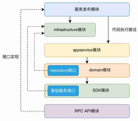
Architecture evolution from MVC to DDD

Four basic strategies for migrating cloud computing workloads
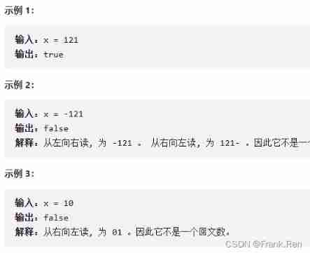
Number of palindromes in C language (leetcode)

Golang lock
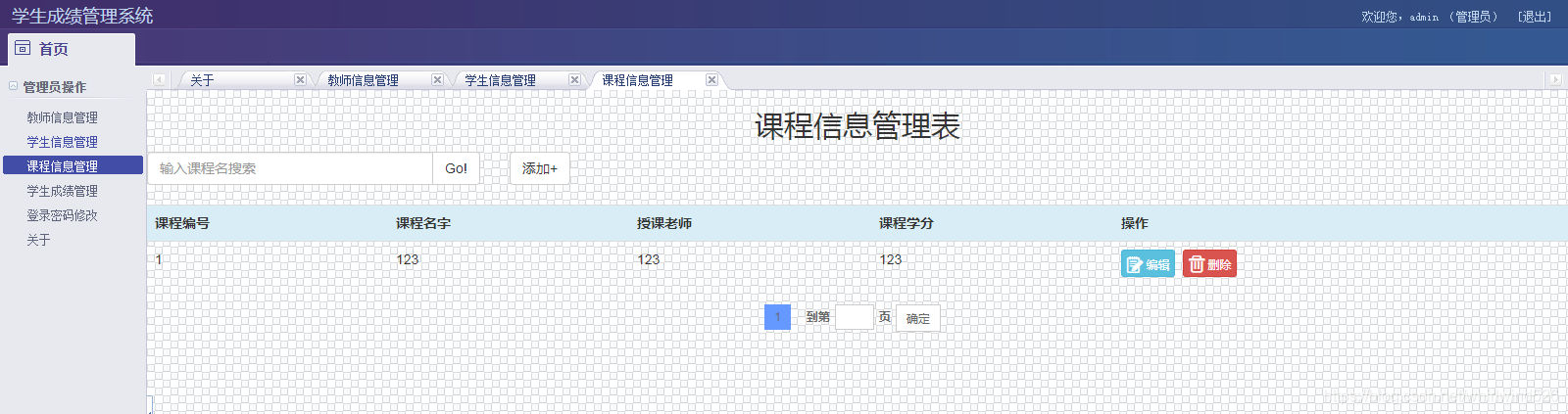
Ks006 student achievement management system based on SSM
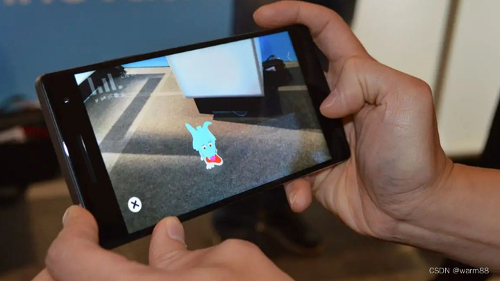
Ar Augmented Reality applicable scenarios
How to execute an SQL in MySQL

Cross domain? Homology? Understand what is cross domain at once

How to debug apps remotely and online?
随机推荐
Sword finger offer 47 Maximum value of gifts
Discussion on the idea of platform construction
开发那些事儿:如何利用Go单例模式保障流媒体高并发的安全性?
Cross domain? Homology? Understand what is cross domain at once
Learn basic K-line diagram knowledge in three minutes
Opengauss database backup and recovery guide
【视频】马尔可夫链蒙特卡罗方法MCMC原理与R语言实现|数据分享
大学的知识是否学而无用、过时?
Software No.1
The concept, function, characteristics, creation and deletion of MySQL constraints
"C language programming", 4th Edition, edited by he Qinming and Yan Hui, after class exercise answers Chapter 3 branch structure
剑指 Offer 62. 圆圈中最后剩下的数字
Makefile simple induction
The smart Park "ZhongGuanCun No.1" subverts your understanding of the park
自动浏览拼多多商品
Spend a week painstakingly sorting out the interview questions and answers of high-frequency software testing / automated testing
leetcode2305. 公平分发饼干(中等,周赛,状压dp)
Deep learning: a solution to over fitting in deep neural networks
leetcode2309. The best English letters with both upper and lower case (simple, weekly)
1217 supermarket coin processor