当前位置:网站首页>QGC ground station tutorial
QGC ground station tutorial
2022-06-11 01:36:00 【Mbot】
List of articles
Preface
QGC Ground station version :
V4.0.8
Ubuntu 18.04
PX4 The firmware
One 、 Download firmware
Don't connect the flight control first , Click on the following page , And then use USB Connect the fly to the computer , Be careful not to use batteries or other USB Power supply to other equipment 
Two 、 Choose a model
Connect the flight control to the ground station , Set the rack to the model you want to set 
Then the upper right side of the motor “ Apply and restart ”
After restart, it is shown in the figure :
3、 ... and 、 calibration
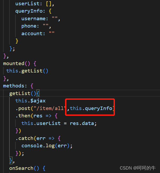
Link the flight control through data transmission QGC Ground station
1. calibrate compass
Select sensor -> compass -> determine , Start calibration 
Place the drone in any direction shown in red , And keep still . When prompted ( The orientation image turns yellow ), Arbitrarily along / Rotate the vehicle about the specified axis in both directions . After the current direction calibration is completed , The relevant image on the screen will turn green .
Repeat the calibration process for all directions .
After calibration in all directions ,QGroundControl Will be displayed Calibration complete( Calibration complete )( All directional images will be displayed in green , The progress bar will be completely filled ). Then you can move on to the next sensor .
2. Calibrate the gyroscope
Click the gyro sensor button , Place the drone horizontally on the ground , Keep still . single click “ determine ” Start calibration . The full bar graph at the top indicates successful calibration 
3. Calibrate the accelerometer
Click the accelerometer sensor button , single click “ determine ” Start calibration .
Follow the directions on the screen , When the orientation image turns yellow , Keep the drone stationary . After the current direction calibration is completed , The relevant image on the screen will turn green .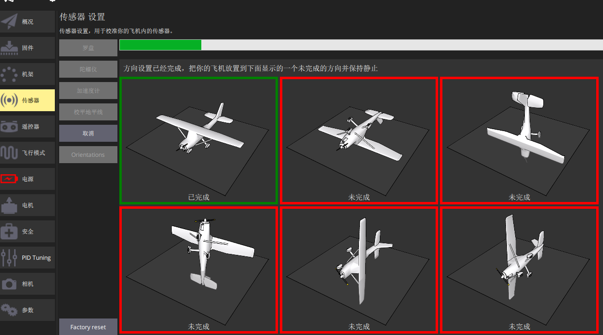
Repeat the calibration process for all directions . After calibrating the vehicle in all positions ,QGroundControl Will be displayed Calibration complete( Calibration complete )( All directional images will be displayed in green , The progress bar will be completely filled ).
4. Calibrate the horizon
If you don't calibrate the horizon , The position of UAV may drift continuously in non fixed point flight .
Place the UAV on a horizontal plane , Click to level the horizon ->OK, Then stay still , Until the green progress bar is full 
5. Calibrate the remote control
Turn on the remote control , Switch to the remote control page , Check whether the channel can be recognized in the lower right corner , If you can identify the channel , You can calibrate , Select the operation mode in the upper right corner , Then click calibrate 
And then click “ determine ”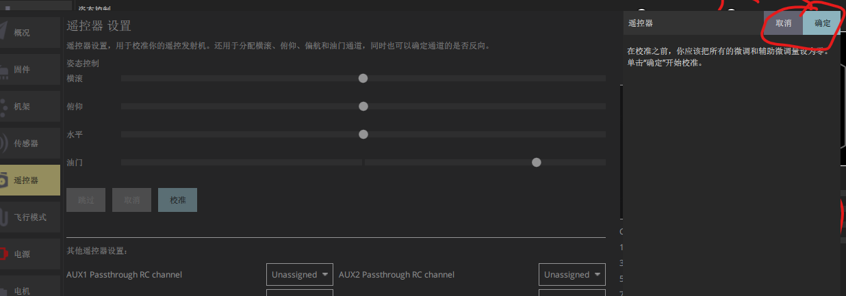
Click again “ next step ”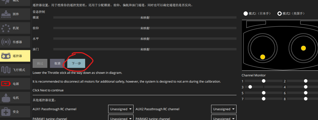
Move the remote control rocker to the position indicated in the figure below .
When the rod is in place , The ground station will prompt the next position to dial , After dialing all positions , Press two times. “ next step ” Save settings .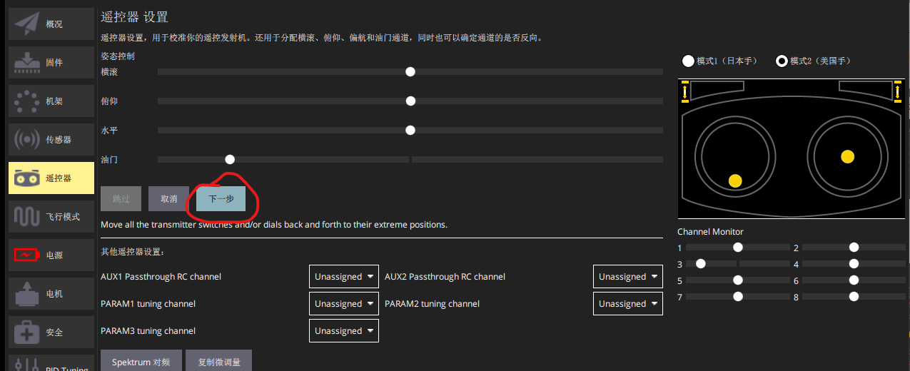
6. Calibrate the electric regulator
Calibrate the electric timing , use USB Connect the flight control to the ground station , No battery connection , No paddle , The signal line of electric regulation is connected to the flight control .
Switch to “ Power Supply ” page , Enter the number of battery cells and press enter , Click on “ calibration ”, Then plug in the battery to calibrate .
Four 、 Set the remote control dial switch
Switch to the flight mode page , You can dial the remote control dial switch that needs to be set first , See which channel it corresponds to in the ground station .
1. Set the flight mode switch
Click on “ Mode channel ” The check box on the right , Set the corresponding remote control dial switch channel .
Then set the flight mode corresponding to the third gear .
2. Set other change-over switches
Other switch channels are on the right side of flight mode , as follows , Which... Needs to be set , Just set the remote control channel on the right side of the switch , I have a brake here (Kill switch), Channel is the fifth channel of the remote control . The function of the brake is to stop the motor directly , Can be set as required 
5、 ... and 、 Flight view page setup
Set the value to be displayed on the flight page , Click on the icon below
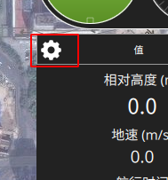
What needs to be displayed , Put a tick on the corresponding left , Final point determination 
6、 ... and 、 Route planning
Pay attention to route planning , After setting the waypoint , There is a... In the bottom left corner of the page “ Terrain height ” That column , The waypoint marked in red indicates that the corresponding waypoint altitude cannot reach . The default altitude is the altitude relative to the takeoff point , For example, the altitude of the takeoff point is 5 rice , Then the altitude of each waypoint must be at least greater than 5 Rice won't be marked red , If it is less than 5 The rice will be marked red , If it is marked in red, the task mode cannot be executed .
If marked in red , You can raise the height a little , Or change it to the height relative to the terrain , as follows .
1. Manual dot
Click on the file -》 blank 
Default must be set first takeoff spot , To set other waypoints 
If you do not want to set takeoff Set the waypoint directly at ( For example, unmanned ships and other vehicles ), You can check the following options in the general settings of the ground station :
Then you can set the waypoint directly without setting the takeoff point .
Click on “takeoff” after , The takeoff point will be generated at the current position of the UAV , Then click “ a stop en route ” Button , Then click on the map to set the waypoint position . The set waypoint can also be selected with the left mouse button and dragged to change its position .
I click the take-off point here , Three waypoints have been set up , There are four points in total , Here's the picture , On the right side of the map, there is a setting page for each line point .
Click the small trash can icon on the left of the corresponding waypoint to delete the waypoint .
Click... On the right side of the small trash can icon Waypoint You can set the type of point , The default is Basic Category , There is Waypoint( a stop en route )、Return To Launch( Return to takeoff point )、Land( land )、Takeoff( take off ) Four kinds of , Corresponding to the actions to be performed after arriving at the waypoint .
The above four points are enough for the use of ordinary four rotors , But if you need to perform some advanced actions ( Such as vertical mode switching ), You need to find... In other categories below .
I set the first point here as the takeoff point 、 The second and third points are set as waypoints , The fourth point is set as the return point , In this case, the UAV will take off and fly to the second point first , Fly to the third point , After reaching the third point, return to the take-off point .
stay Mission Start In that column, the waypoint altitude and flight speed can be set to be equivalent , The settings in this column will be valid for all task points .
You can also set the equivalent height and dwell time in each task point , But the settings here are only valid for this task point , There is a three bar icon on the right side of each task point , You can click this icon to set more information about this task point 
Here's the picture :
“ Edit location ” You can edit the position in detail 
“ Show all values ” You can edit all the parameters of the task point 
2. Rectangular wave type surveying and mapping planning
Click on the pattern -》 Mapping 
Click to sketch , Then point the vertices of the polygon on the map

Click to finish sketching 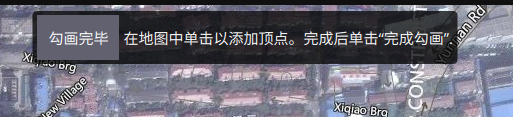
Click the following figure to edit 
The interval can be set , angle , Turning distance, etc 
If you want to change the unit of route distance set in the figure below into meters

Just disable the camera 

5、 ... and 、 Set the parameter adjustment channel of the remote controller
By setting the parameter adjustment channel , You can connect a certain channel of the remote control ( Such as knob ) Mapping to PX4 One of the parameters of , Thus, it can be adjusted in real time through the knob of the remote control PX4 The value of the parameter .
In the figure below, first set the remote control channel corresponding to the parameter , Up to three parameter channels can be set at the same time .
For example, the remote control knob here corresponds to the channel 9, I'll take the parameter 1 The parameter adjustment channel of is set as the channel of the remote controller 9.
The inner loop pitch rate is then mapped to the parameter 1 On , Click Advanced settings below -》 Set the remote control to parameter …
Then set the zoom factor . After setting, you can move the knob to see if the parameter changes normally
边栏推荐
- 百万级访问量—高并发问题的解决历程
- SAS discriminant analysis (Bayes criterion and proc discrim process)
- [interpretation of the paper] sort out the papers on the vision based autonomous landing platform of UAV
- 快递鸟系统对接
- I was so excited about the college entrance examination in 2022
- OCR文字识别经典论文详解
- Beijing Tongzhou District high tech enterprise cultivation support standard, with a subsidy of 100000 yuan
- Understanding of multithreading
- Current limiting and download interface request number control
- Solution to prompt "network initialization failed operation failed" in PD virtual machine installation system
猜你喜欢

焱融看|混合云环境下,如何实现数据湖最优存储解决方案

Basic introduction of graph and depth first traversal and breadth first traversal
node和express实现mySql模糊搜索

中间件_Redis_06_Redis的事务
Yanrong looks at how to realize the optimal storage solution of data Lake in a hybrid cloud environment
Implementing MySQL fuzzy search with node and express

Middleware_ Redis_ 05_ Persistence of redis

Solution to prompt "network initialization failed operation failed" in PD virtual machine installation system

Multi interest recall model practice | acquisition technology
多兴趣召回模型实践|得物技术
随机推荐
多兴趣召回模型实践|得物技术
北京房山区高新技术企业培育支持标准,补贴10万
SAS cluster analysis (system cluster, dynamic cluster fastclus, variable cluster varclus)
中间件_Redis_05_Redis的持久化
Bubble sort and quick sort
Support standard for cultivation of high-tech enterprises in Changping District, Beijing, with a subsidy of 100000 yuan
MultipartFile和File互转工具类
项目_基于网络爬虫的疫情数据可视化分析
QGC地面站使用教程
About mobx
Beijing Dongcheng District high tech enterprise cultivation support standard, with a subsidy of 100000 yuan
1.7、PX4遥控器校准
Introduction to the application process of China Patent Award, with a subsidy of 1million yuan
什么是C端 什么是B端 这里告诉你
Throttling and anti chattering of functions
记录打包GoogleChrome浏览器插件
How to use user-defined annotation for parameter verification
SAS factor analysis (proc factor process, factor rotation and regression method for factor score function)
Sealem Finance打造Web3去中心化金融平台基础设施
Oracle relational tables with XY field values are synchronized to PG database and converted to geometric fields