当前位置:网站首页>Object distance measurement of stereo vision
Object distance measurement of stereo vision
2022-07-04 15:43:00 【Xiaobai learns vision】
In the process of modern industrial automation , Computer vision is becoming one of the key technologies to improve production efficiency and check product quality , For example, automatic detection of machine parts , Intelligent robot control , Automatic monitoring of production line .
In the field of national defense and aerospace , Computer vision also has more important significance , For example, automatic tracking and recognition of moving targets , Navigation of autonomous vehicle and visual control of space robots .
The purpose of computer vision research is to enable computers to recognize three-dimensional environmental information through two-dimensional image information . This function not only enables the machine to perceive the geometric information of objects in the three-dimensional environment ( For example, shape , Location , Postural movement, etc ), And it can be further described , Storage , Recognize and understand them , Computer vision has developed a set of independent computing theory and Algorithm .
In this paper , We introduced the related content of stereo vision , That is, multiple camera views are used to obtain information about the view depth . Use stereo vision , The world position of a point can be obtained from the images in different camera views .
Stereo vision
Binocular stereo vision is an important form of machine vision . It's based on parallax principle , And use imaging equipment to obtain two images of the measured object from different positions .
Take the left and right input images with dense stereo vision ,
These images are shifted and matched to generate the depth of each pixel .
Combine the images obtained from the two positions and observe the differences between them , In order to get a clear sense of depth , Establish the corresponding relationship between features , And map the same physical points in the same space to image points in different images . This difference is called Parallax map .
Polar geometry
Polar geometry It is the special geometric relationship between the two images generated by the camera in two different positions and the shooting position and the generated image . The basic geometric model is shown below :
The camera is centered by the camera C,C' And their respective imaging plane representation . For points in any space X, The points on the two image planes are x,x'.
spot x Project backward into three-dimensional rays in space , The three-dimensional ray is composed of the camera center and x determine . Cast the ray onto the second image plane , In order to get what is called Epipolar line The straight line of l' . Obviously, the protrusion X“ Of X Must be L”. We can also draw a line connecting the center of two cameras . The point where the line intersects the image plane is called pole . Because in the case of stereo cameras , We have two cameras , So there is a line and two image planes , So we have two sub poles .
Consider a plane that does not pass through the center of any two cameras in space π, And through the center of the first camera C and x The light of X Place and plane π The intersection , Then project the point onto the point . The second image x', This process is flat π Translation of .
actually , All points xi And corresponding points x'i The projection of on the first image is actually equivalent , Because they are equivalent to coplanar points in projection Xi Set , Therefore exist 2D mapping H, Every xi All mapped to x' The first world .
Derivation of basic matrix and basic matrix
From the geometric description of camera imaging , We can understand the following formula :
among K It is the internal parameter of the camera ,R and t Is the external parameter of the second camera in the camera coordinate system of the first camera ,Pw Is the point coordinate in the coordinate system of the first camera .Z Is the distance from the space point to the optical center of the camera .
We first define the standardized coordinates of the camera , As shown below
By introducing the above definition, we can get :
At the same time t External product of :
Place x_2 Multiply by the left :
In the formula above , Due to equation t ^ x_2 The left side of is perpendicular to t and x_2 Vector , therefore x_2 The inner product of will be 0, Therefore, the above formula can actually be expressed in the following form :
Replace x_1 and x_2 And reinsert p_ {uv1} and p_ {uv2} obtain :
among , The middle term is Basic matrix , It meets the following conditions :
Basic matrix yes Basic matrix Part of , Only related to external parameters , in other words , Delete camera internal parameters , You can get :
Basic matrix The degrees of freedom of includes three translational and rotational degrees of freedom , Plus the equivalent proportion , So the basic matrix The degree of freedom of is 5.
therefore , At least we can use 5 Point to point solution Basic matrix . however , Because many of their inherent properties are nonlinear , Therefore, using the least number of points will be more troublesome , Therefore, only the equivalence of proportion is usually considered , And then use 8 Solving points . This is also called Eight point method .
Consider a pair of matching points and their pixel coordinates . According to polar constraints , Yes :
Expand the above matrix and write it as a vector :
here , The above limit constraint equation can be written as :
By putting the antipodal constraints of eight points together, we can get a system of equations :
Basic matrix or basic matrix can be solved by solving equations .
Complete the above work , Solve the basic matrix E after , Can pass SVD Decompose to obtain the following equation :
among U and V It's an orthogonal matrix , In the middle of the X Is a singular value matrix . according to E The inherent nature of , We go through SVD Decomposition knows , For any E, There are two possibilities R and t Corresponding to it .
among :
Stereo correction
Due to misalignment and different characteristics , The images of both stereo cameras must be distorted into a new image with polar alignment . These new images are called Verification Images . The whole process is called “ correction ”, Then twist the image plane onto a coplanar parallel plane .
Use the calibration process , We hope to deform the left and right cameras , So that the image is coplanar and the intrinsic function is the same . Use Homography , We can use the original image coodinates To express that :
therefore , Now we can ask a question : How to get K ^ and R ^. Some good choices are :
among ,
among rL_3 It's the left camera R_L The third column of the rotation matrix of .
Parallax map
The camera imaging model is shown in the figure below :
among ,P It's a space point ,f It's focal length ,Cr,Cl It is the optical center of the left and right cameras . As can be seen from the figure below , The optical axes of the left and right cameras are parallel .Ul and Ur Is the distance between two imaging points on the left and right image planes, and the distance between the left edge of the image .
If two cameras have been calibrated , Then the polar lines are parallel , And the directions of the two optical axes are also parallel .
Then the relationship between parallax and object depth is as follows :
From this we can conclude that :
According to the formula ,b and f Constant ,Z And ul-ur In inverse proportion , That is, the smaller the depth , The greater the parallax , And the greater the parallax of the object . This is why the closer objects in the parallax map are darker .
The basic principle is , A point on a given image , Select a sub window near the pixel , And according to certain similarity judgment basis , In the area of another image , Select the image closest to the sub window .- window .
The matching cost is calculated for each pixel of the left image and the right image . It can be considered as a function
A method for processing matching pixels in left and right images is defined , among d = ul-ur Is the minimum parallax range we define :
If you do this for every pixel , The final parallax map can be obtained , But the effect of the final parallax map is very poor . The matching between points is easily affected by noise , Therefore, we need to establish a window around the point to compare pixel blocks , This is definitely more reliable .
As long as it contains enough texture , This method can work well . If the texture is insufficient , Then the similarity difference between the two will not be much different , And a single match point cannot be identified . however , This is a solution . As long as there is not enough texture , We can expand it until there is texture .
Refrences
• R. Szeliski, Computer Vision: Algorithms and Applications, Springer, 2010.
• B. H. Bodkin, Real-time mobile stereo vision [M.S. thesis], University of Tennessee, 2012.
• M. Hansard, S. Lee, O. Choi, and R. P. Horaud, Time-of-Flight Cameras: Principles, Methods and Applications, Springer, 2012.
• S. Foix, G. Alenyà, and C. Torras, “Lock-in time-of-flight (ToF) cameras: a survey,” IEEE Sensors Journal, vol. 11, no. 9, pp. 1917–1926, 2011. View at: Publisher Site | Google Scholar
• M. Y. Kim, S. M. Ayaz, J. Park, and Y. Roh, “Adaptive 3D sensing system based on variable magnification using stereo vision and structured light,” Optics and Lasers in Engineering, vol. 55, pp. 113–127, 2014. View at: Publisher Site | Google Scholar
• S. Zhang, C. Wang, and S. C. Chan, “A new high resolution depth map estimation system using stereo vision and depth sensing device,” in Proceedings of the IEEE 9th International Colloquium on Signal Processing and Its Applications (CSPA ‘13), pp. 49–53, IEEE, Kuala Lumpur, Malaysia, March 2013. View at: Publisher Site | Google Scholar
• W. Kazmi, S. Foix, G. Alenyà, and H. J. Andersen, “Indoor and outdoor depth imaging of leaves with time-of-flight and stereo vision sensors: analysis and comparison,” ISPRS Journal of Photogrammetry and Remote Sensing, vol. 88, pp. 128–146, 2014. View at: Publisher Site | Google Scholar
• B. Tippetts, D. J. Lee, K. Lillywhite, and J. Archibald, “Review of stereo vision algorithms and their suitability for resource-limited systems,” Journal of Real-Time Image Processing, pp. 1–21, 2013. View at: Publisher Site | Google Scholar
边栏推荐
- How to rapidly deploy application software under SaaS
- MySQL learning notes - data type (2)
- Force button brush question 01 (reverse linked list + sliding window +lru cache mechanism)
- 进制乱炖
- Halcon knowledge: NCC_ Model template matching
- 一篇文章学会GO语言中的变量
- Data Lake Governance: advantages, challenges and entry
- Unity prefab day04
- 浮点数如何与0进行比较?
- Unity脚本介绍 Day01
猜你喜欢
MySQL组合索引(多列索引)使用与优化案例详解
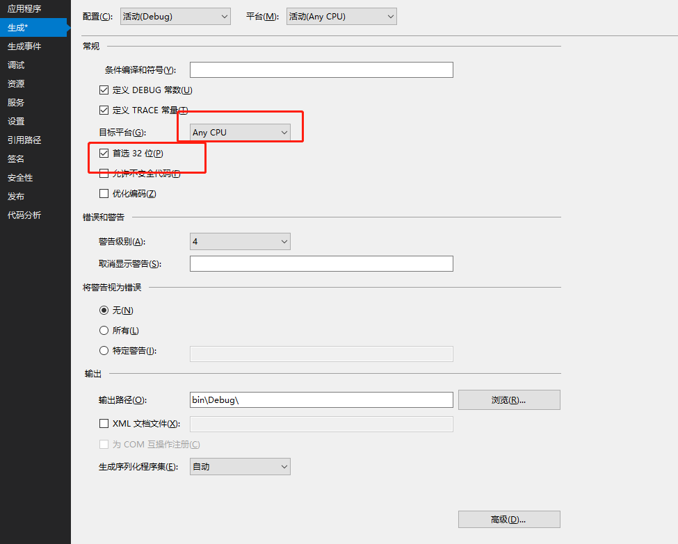
. Net applications consider x64 generation
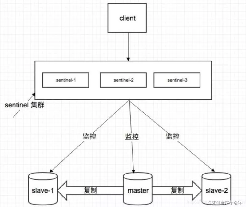
Redis sentinel mode realizes one master, two slave and three Sentinels
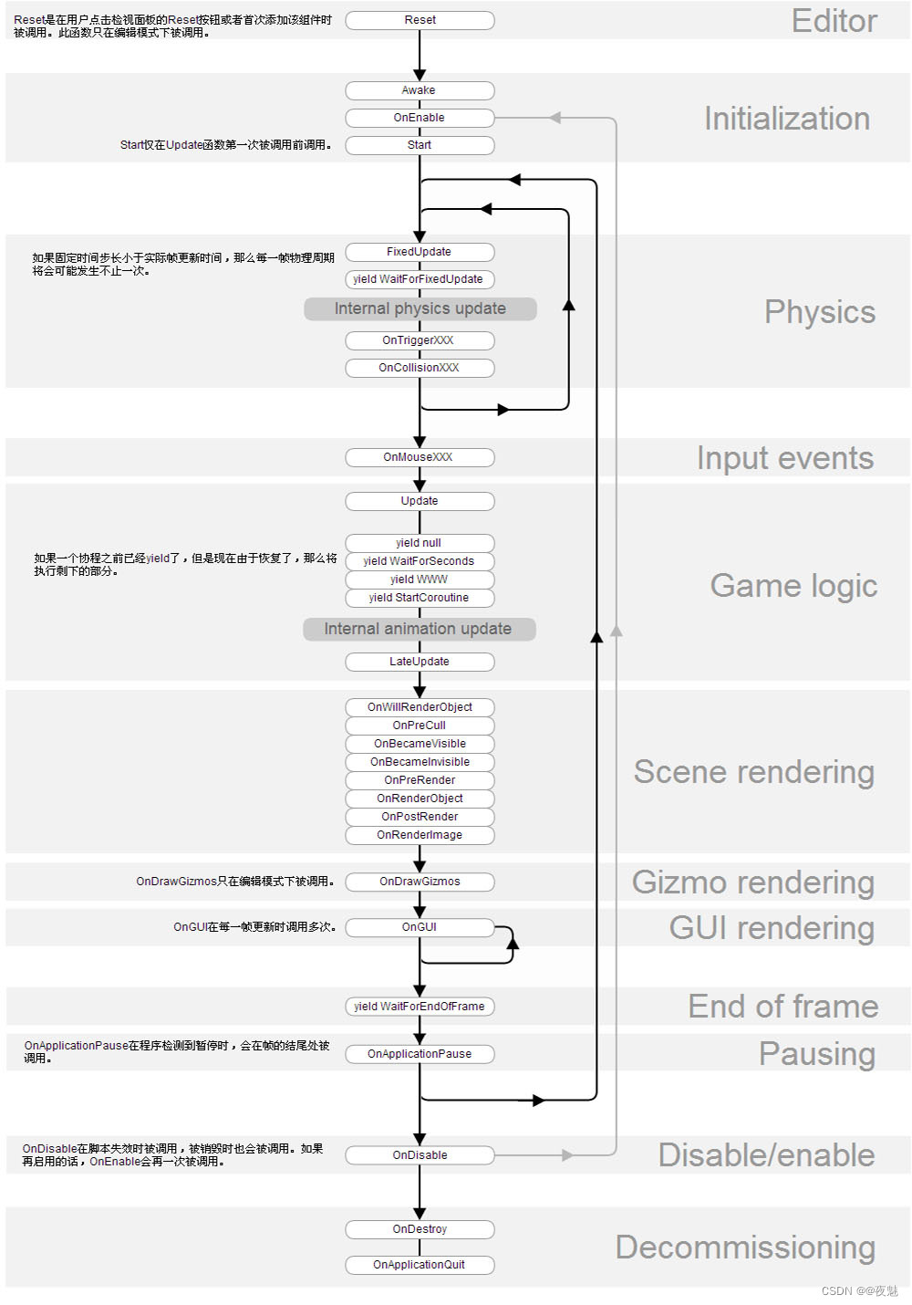
Unity脚本生命周期 Day02

Unity动画Animation Day05
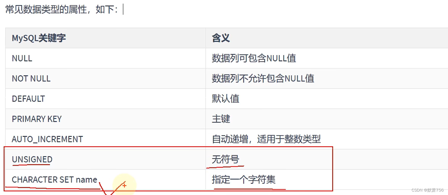
MySQL学习笔记——数据类型(数值类型)
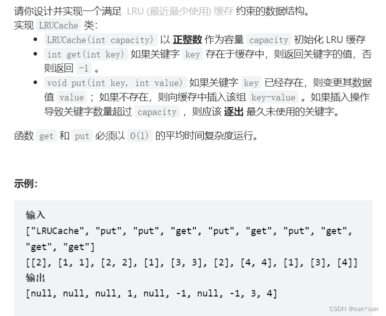
力扣刷题01(反转链表+滑动窗口+LRU缓存机制)
.Net 应用考虑x64生成
![[Dalian University of technology] information sharing of postgraduate entrance examination and re examination](/img/06/df5a64441814c9ecfa2f039318496e.jpg)
[Dalian University of technology] information sharing of postgraduate entrance examination and re examination

Dry goods | fMRI standard reporting guidelines are fresh, come and increase your knowledge
随机推荐
Detailed explanation of MySQL composite index (multi column index) use and optimization cases
Nine CIO trends and priorities in 2022
I plan to teach myself some programming and want to work as a part-time programmer. I want to ask which programmer has a simple part-time platform list and doesn't investigate the degree of the receiv
[book club issue 13] ffmpeg common methods for viewing media information and processing audio and video files
Numpy notes
Enter the width!
.Net之延迟队列
【读书会第十三期】FFmpeg 查看媒体信息和处理音视频文件的常用方法
Width accuracy
Halcon knowledge: NCC_ Model template matching
力扣刷题01(反转链表+滑动窗口+LRU缓存机制)
找数字
LeetCode 1184. 公交站间的距离 ---vector顺逆时针
Preliminary exploration of flask: WSGI
Guitar Pro 8win10 latest guitar learning / score / creation
Weibo and Huya advance into interest communities: different paths for peers
MySQL federated primary key_ MySQL creates a federated primary key [easy to understand]
%f格式符
开源人张亮的 17 年成长路线,热爱才能坚持
文本挖掘工具的介绍[通俗易懂]