当前位置:网站首页>Running lantern experiment based on stm32f103zet6 library function
Running lantern experiment based on stm32f103zet6 library function
2022-06-27 19:18:00 【It's Beichen bupiacra】
be based on STM32F103ZET6 Library function horse lamp experiment
IO Of 8 Patterns
1、 Enter the float
2、 Input pull-up
3、 Type in the dropdown
4、 Analog input
5、 Open drain output
6、 Push pull output
7、 Push pull multiplexing
8、 Open drain multiplexing function
GPIO Related functions
GPIO_Init Declaration of functions
In firmware library development , Operation register CRH and CRL To configure the IO The mode and speed of the port are through GPIO initialization Function completion :
void GPIO_Init(GPIO_TypeDef* GPIOx, GPIO_InitTypeDef* GPIO_InitStruct);
This function has two arguments , The first parameter is used to specify GPIO, The value range is GPIOA~GPIOG.
every last GPIO You can configure so many registers in the following structure
/** * @brief General Purpose I/O */

typedef struct
{

  __IO uint32_t CRL;
  __IO uint32_t CRH;
  __IO uint32_t IDR;
  __IO uint32_t ODR;
  __IO uint32_t BSRR;
  __IO uint32_t BRR;
  __IO uint32_t LCKR;
} GPIO_TypeDef;
The second parameter is the initialization parameter structure pointer , The structural type is GPIO_InitTypeDef.
/** * @brief GPIO Init structure definition */

typedef struct
{

  uint16_t GPIO_Pin;             /*!< Specifies the GPIO pins to be configured. This parameter can be any value of @ref GPIO_pins_define */

  GPIOSpeed_TypeDef GPIO_Speed;  /*!< Specifies the speed for the selected pins. This parameter can be a value of @ref GPIOSpeed_TypeDef */

  GPIOMode_TypeDef GPIO_Mode;    /*!< Specifies the operating mode for the selected pins. This parameter can be a value of @ref GPIOMode_TypeDef */
}GPIO_InitTypeDef;
GPIO_Init Definition of function
void GPIO_Init(GPIO_TypeDef* GPIOx, GPIO_InitTypeDef* GPIO_InitStruct)
{

  uint32_t currentmode = 0x00, currentpin = 0x00, pinpos = 0x00, pos = 0x00;
  uint32_t tmpreg = 0x00, pinmask = 0x00;
  /* Check the parameters */
  assert_param(IS_GPIO_ALL_PERIPH(GPIOx));
  assert_param(IS_GPIO_MODE(GPIO_InitStruct->GPIO_Mode));
  assert_param(IS_GPIO_PIN(GPIO_InitStruct->GPIO_Pin));

/*---------------------------- GPIO Mode Configuration -----------------------*/
  currentmode = ((uint32_t)GPIO_InitStruct->GPIO_Mode) & ((uint32_t)0x0F);
  if ((((uint32_t)GPIO_InitStruct->GPIO_Mode) & ((uint32_t)0x10)) != 0x00)
  {

    /* Check the parameters */
    assert_param(IS_GPIO_SPEED(GPIO_InitStruct->GPIO_Speed));
    /* Output mode */
    currentmode |= (uint32_t)GPIO_InitStruct->GPIO_Speed;
  }
/*---------------------------- GPIO CRL Configuration ------------------------*/
  /* Configure the eight low port pins */
  if (((uint32_t)GPIO_InitStruct->GPIO_Pin & ((uint32_t)0x00FF)) != 0x00)
  {

    tmpreg = GPIOx->CRL;
    for (pinpos = 0x00; pinpos < 0x08; pinpos++)
    {

      pos = ((uint32_t)0x01) << pinpos;
      /* Get the port pins position */
      currentpin = (GPIO_InitStruct->GPIO_Pin) & pos;
      if (currentpin == pos)
      {

        pos = pinpos << 2;
        /* Clear the corresponding low control register bits */
        pinmask = ((uint32_t)0x0F) << pos;
        tmpreg &= ~pinmask;
        /* Write the mode configuration in the corresponding bits */
        tmpreg |= (currentmode << pos);
        /* Reset the corresponding ODR bit */
        if (GPIO_InitStruct->GPIO_Mode == GPIO_Mode_IPD)
        {

          GPIOx->BRR = (((uint32_t)0x01) << pinpos);
        }
        else
        {

          /* Set the corresponding ODR bit */
          if (GPIO_InitStruct->GPIO_Mode == GPIO_Mode_IPU)
          {

            GPIOx->BSRR = (((uint32_t)0x01) << pinpos);
          }
        }
      }
    }
    GPIOx->CRL = tmpreg;
  }
/*---------------------------- GPIO CRH Configuration ------------------------*/
  /* Configure the eight high port pins */
  if (GPIO_InitStruct->GPIO_Pin > 0x00FF)
  {

    tmpreg = GPIOx->CRH;
    for (pinpos = 0x00; pinpos < 0x08; pinpos++)
    {

      pos = (((uint32_t)0x01) << (pinpos + 0x08));
      /* Get the port pins position */
      currentpin = ((GPIO_InitStruct->GPIO_Pin) & pos);
      if (currentpin == pos)
      {

        pos = pinpos << 2;
        /* Clear the corresponding high control register bits */
        pinmask = ((uint32_t)0x0F) << pos;
        tmpreg &= ~pinmask;
        /* Write the mode configuration in the corresponding bits */
        tmpreg |= (currentmode << pos);
        /* Reset the corresponding ODR bit */
        if (GPIO_InitStruct->GPIO_Mode == GPIO_Mode_IPD)
        {

          GPIOx->BRR = (((uint32_t)0x01) << (pinpos + 0x08));
        }
        /* Set the corresponding ODR bit */
        if (GPIO_InitStruct->GPIO_Mode == GPIO_Mode_IPU)
        {

          GPIOx->BSRR = (((uint32_t)0x01) << (pinpos + 0x08));
        }
      }
    }
    GPIOx->CRH = tmpreg;
  }
}
GPIO_Init Use of functions
Initialize by initializing structure GPIO The common format of is :
GPIO_InitTypeDef  GPIO_InitStructure;

GPIO_InitStructure.GPIO_Pin = GPIO_Pin_5;  //LED0-->PB.5  port configuration
GPIO_InitStructure.GPIO_Mode = GPIO_Mode_Out_PP;    // Push pull output
GPIO_InitStructure.GPIO_Speed = GPIO_Speed_50MHz;// Speed  50MHz

GPIO_Init(GPIOB, &GPIO_InitStructure);// According to the set parameter configuration  GPIO
Let's take a look GPIO_InitStructure What parameters can be set for members in the structure
Structure GPIO_InitStructure The first member variable of GPIO_Pin Used to set to initialize Which or which IO mouth
/** @defgroup GPIO_pins_define * @{ */

#define GPIO_Pin_0 ((uint16_t)0x0001) /*!< Pin 0 selected */
#define GPIO_Pin_1 ((uint16_t)0x0002) /*!< Pin 1 selected */
#define GPIO_Pin_2 ((uint16_t)0x0004) /*!< Pin 2 selected */
#define GPIO_Pin_3 ((uint16_t)0x0008) /*!< Pin 3 selected */
#define GPIO_Pin_4 ((uint16_t)0x0010) /*!< Pin 4 selected */
#define GPIO_Pin_5 ((uint16_t)0x0020) /*!< Pin 5 selected */
#define GPIO_Pin_6 ((uint16_t)0x0040) /*!< Pin 6 selected */
#define GPIO_Pin_7 ((uint16_t)0x0080) /*!< Pin 7 selected */
#define GPIO_Pin_8 ((uint16_t)0x0100) /*!< Pin 8 selected */
#define GPIO_Pin_9 ((uint16_t)0x0200) /*!< Pin 9 selected */
#define GPIO_Pin_10 ((uint16_t)0x0400) /*!< Pin 10 selected */
#define GPIO_Pin_11 ((uint16_t)0x0800) /*!< Pin 11 selected */
#define GPIO_Pin_12 ((uint16_t)0x1000) /*!< Pin 12 selected */
#define GPIO_Pin_13 ((uint16_t)0x2000) /*!< Pin 13 selected */
#define GPIO_Pin_14 ((uint16_t)0x4000) /*!< Pin 14 selected */
#define GPIO_Pin_15 ((uint16_t)0x8000) /*!< Pin 15 selected */
#define GPIO_Pin_All ((uint16_t)0xFFFF) /*!< All pins selected */
The second member variable GPIO_Mode It is used to set the corresponding IO Output input mode of the port , These patterns are explained above 8 A model , stay MDK Is defined by an enumeration type :
typedef enum
{

	GPIO_Mode_AIN = 0x0,      // Analog input
	GPIO_Mode_IN_FLOATING = 0x04, // Floating input
	GPIO_Mode_IPD = 0x28,    // Drop down input
	GPIO_Mode_IPU = 0x48,    // Pull up input
	GPIO_Mode_Out_OD = 0x14,   // Open drain output
	GPIO_Mode_Out_PP = 0x10,   // General push-pull output
	GPIO_Mode_AF_OD = 0x1C,   // Reuse open drain output
	GPIO_Mode_AF_PP = 0x18   // Reuse push pull
}GPIOMode_TypeDef;
The third parameter is IO Mouth speed setting , There are three optional values , stay MDK It is also defined by enumeration type :
typedef enum
{

	GPIO_Speed_10MHz = 1,
	GPIO_Speed_2MHz,
	GPIO_Speed_50MHz
}GPIOSpeed_TypeDef;
Here, only the first enumeration member is assigned the value 1, But the value of the following member is incremented with the previous one
GPIO_ReadInputDataBit
Operate in firmware library IDR Register read IO Port data is through GPIO_ReadInputDataBit Functionally implemented :
uint8_t GPIO_ReadInputDataBit(GPIO_TypeDef* GPIOx, uint16_t GPIO_Pin);
For example, I want to read GPIOB.5 The level state of , So the way is :
GPIO_ReadInputDataBit(GPIOB, GPIO_Pin_5);
The return value is 1(Bit_SET) perhaps 0(Bit_RESET);
GPIO_Write
Set... In the firmware library ODR Register value to control IO The output state of the port is through the function GPIO_Write To achieve Of :
void GPIO_Write(GPIO_TypeDef* GPIOx, uint16_t PortVal);
This function is generally used to go one at a time GPIO Multiple port settings for .
GPIO_SetBits、 GPIO_ResetBits
stay STM32 Firmware library , adopt BSRR and BRR Set register GPIO The port output is through the function GPIO_SetBits() And the function GPIO_ResetBits() To complete .
void GPIO_SetBits(GPIO_TypeDef* GPIOx, uint16_t GPIO_Pin);
void GPIO_ResetBits(GPIO_TypeDef* GPIOx, uint16_t GPIO_Pin);
We need to set Set up GPIOB.5 Output 1, Then the method is :
GPIO_SetBits(GPIOB, GPIO_Pin_5);
Conversely, if you want to set GPIOB.5 Output bit 0, Method is :
GPIO_ResetBits (GPIOB, GPIO_Pin_5);
IO Operation steps
1) Can make IO Port clock . The call function is RCC_APB2PeriphClockCmd();
2) initialization IO Parameters . Call function GPIO_Init();
3) operation IO. operation IO The method of is the method we explained above .
 GPIO_InitTypeDef  GPIO_InitStructure;

 RCC_APB2PeriphClockCmd(RCC_APB2Periph_GPIOB|RCC_APB2Periph_GPIOE, ENABLE);	 // Can make PB,PE Port clock

 GPIO_InitStructure.GPIO_Pin = GPIO_Pin_5;				 //LED0-->PB.5  port configuration
 GPIO_InitStructure.GPIO_Mode = GPIO_Mode_Out_PP; 		 // Push pull output
 GPIO_InitStructure.GPIO_Speed = GPIO_Speed_50MHz;		 //IO The mouth speed is 50MHz
 GPIO_Init(GPIOB, &GPIO_InitStructure);					 // Initialize according to the set parameters GPIOB.5
 GPIO_SetBits(GPIOB,GPIO_Pin_5);						 //PB.5  High output

 GPIO_InitStructure.GPIO_Pin = GPIO_Pin_5;	    		 //LED1-->PE.5  port configuration
 GPIO_Init(GPIOE, &GPIO_InitStructure);	  				 // Initialize according to the set parameters GPIOE.5
 GPIO_SetBits(GPIOE,GPIO_Pin_5); 						 //PE.5  High output
Because the two one. IO The mode and speed of the mouth are the same , So we only need to initialize once , stay GPIOE.5 There is no need to repeat the initialization speed and mode when initializing
From the system architecture, you can find PB,PE Port clock 
Find out from the schematic diagram PB5、PE5 by LED0、LED1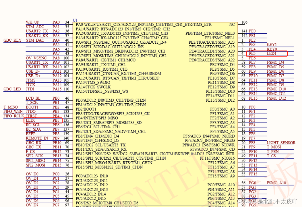
When there is a voltage drop on both sides of the LED , namely PB5、PE5 by 0 when , The LED will light up 
stay led.c In the file LED The initialized function is encapsulated
#include "led.h"

void LED_Init(void)
{

 	GPIO_InitTypeDef  GPIO_InitStructure;

 	RCC_APB2PeriphClockCmd(RCC_APB2Periph_GPIOB|RCC_APB2Periph_GPIOE, ENABLE);	 // Can make PB,PE Port clock

 	GPIO_InitStructure.GPIO_Pin = GPIO_Pin_5;				 //LED0-->PB.5  port configuration
 	GPIO_InitStructure.GPIO_Mode = GPIO_Mode_Out_PP; 		 // Push pull output
	GPIO_InitStructure.GPIO_Speed = GPIO_Speed_50MHz;		 //IO The mouth speed is 50MHz
	GPIO_Init(GPIOB, &GPIO_InitStructure);					 // Initialize according to the set parameters GPIOB.5
	GPIO_SetBits(GPIOB,GPIO_Pin_5);						 //PB.5  High output

 	GPIO_InitStructure.GPIO_Pin = GPIO_Pin_5;	    		 //LED1-->PE.5  port configuration
 	GPIO_Init(GPIOE, &GPIO_InitStructure);	  				 // Initialize according to the set parameters GPIOE.5
	GPIO_SetBits(GPIOE,GPIO_Pin_5); 						 //PE.5  High output
 }
stay led.h Enter the following code
#ifndef __LED_H
#define __LED_H
#include "sys.h"

#define LED0 PBout(5)// PB5
#define LED1 PEout(5)// PE5

void LED_Init(void);//LED initialization


#endif
The key to this code is 2 Macro definition :
#define LED0 PBout(5)// PB5
#define LED1 PEout(5)// PE5
Bit band operation is used to operate a certain IO Oral 1 bits
main.c
#include "led.h"
#include "delay.h"
#include "sys.h"

int main(void)
{

	delay_init();               // Delay function initialization
	LED_Init();              // Initialization and  LED  Connected hardware interface
	while(1)
	{

		LED0=0;
		LED1=1;
		delay_ms(300);            // Time delay  300ms
		LED0=1;
		LED1=0;
		delay_ms(300);            // Time delay  300ms
	}
}
operation IO Three methods of output high and low level of port
Bit band operation
The two macro definitions of bit band operation have been defined above
LED0=1;  // Control by bit band operation  LED0  The pin of  PB5  Output high level
LED0=0;  // Control by bit band operation  LED0  The pin of  PB5  Output low level
Library function operation
GPIO_SetBits(GPIOB, GPIO_Pin_5);        // Set up  GPIOB.5  Output  1, equivalent  LED0=1;
GPIO_ResetBits (GPIOB, GPIO_Pin_5);      // Set up  GPIOB.5  Output  0, equivalent  LED0=0;
Register operation
GPIOB->BRR=GPIO_Pin_5; // Set up  GPIOB.5  Output  1, equivalent  LED0=1;
GPIOE->BSRR=GPIO_Pin_5; // Set up  GPIOB.5  Output  0, equivalent  LED0=0;
边栏推荐
- Galaxy Kirin V10 system activation
- NVIDIA Clara-AGX-Developer-Kit installation
- VS code 运行yarn run dev 报yarn : 无法加载文件XXX的问题
- [notice of the Association] notice on holding summer special teacher training in the field of artificial intelligence and Internet of things
- 国产数据库认证考试指南汇总(2022年6月16日更新)
- 如何封裝調用一個庫
- PostgreSQL数据库WAL——资源管理器RMGR
- 广发期货开户安全吗?
- Campus book resource sharing platform
- Market status and development prospect forecast of global aircraft hose industry in 2022
猜你喜欢

电脑安全证书错误怎么处理比较好

在arcgis中以txt格式导出点的坐标
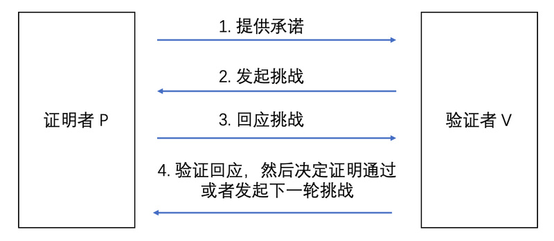
Comprehensively analyze the zero knowledge proof: resolve the expansion problem and redefine "privacy security"

VS code 运行yarn run dev 报yarn : 无法加载文件XXX的问题

Row to column and column to row in MySQL

Application of tdengine in monitoring of CNC machine tools

The IPO of Yuchen Airlines was terminated: Guozheng was proposed to raise 500million yuan as the major shareholder

基于STM32F103ZET6库函数按键输入实验

脉脉热帖:为啥大厂都热衷于造轮子?

Hikvision tools manager Hikvision tools collection (including sadp, video capacity calculation and other tools) a practical tool for millions of security practitioners
随机推荐
MySQL读取Binlog日志常见错误和解决方法
laravel框架中 定时任务的实现
如何实现IM即时通讯“消息”列表卡顿优化
【ELT.ZIP】OpenHarmony啃论文俱乐部—数据密集型应用内存压缩
云原生数据库:数据库的风口,你也可以起飞
新中大冲刺科创板:年营收2.84亿 拟募资5.57亿
maxwell 报错(连接为mysql 8.x)解决方法
明美新能源冲刺深交所:年应收账款超6亿 拟募资4.5亿
Open source summer 2022 | opengauss project selected and announced
教你打印自己的日志 -- 如何自定义 log4j2 各组件
驾驭一切的垃圾收集器 -- G1
【云驻共创】高校数字化差旅建设“解决之道”
MFS distributed file system
How to use the low code platform of the Internet of things for picture management?
基于STM32F103ZET6库函数外部中断实验
Two methods of MySQL database login and logout
开源之夏 2022 | openGauss 项目中选公布
Mise à jour SQL mise à jour par lots
PostgreSQL数据库WAL——资源管理器RMGR
Informatics Orsay all in one 1335: [example 2-4] connected block