当前位置:网站首页>STC 32-bit 8051 single chip microcomputer development example tutorial II i/o working mode and its configuration
STC 32-bit 8051 single chip microcomputer development example tutorial II i/o working mode and its configuration
2022-07-01 19:59:00 【Bill66】
1. I/O Working mode STC 32G Series MCU has at most 64Pin Pin , At most 60 individual I/O mouth . As shown in the figure below :

STC32G A series of single chip computers I/O Every mouth has 4 Working mode : Quasi two-way port ( Weak pull-up )、 Push pull output ( Strong pull up )、 High impedance input ( Current cannot flow in or out )、 Open drain output .P30、P31 The power on reset state is quasi bidirectional ( Weak pull-up ) Pattern , rest I/O The power on reset state of the port is high resistance input , This is related to STC15 series , Somewhat different .
To use I/O Port configuration required I/O Working mode of port ,STC32G Besides the port configuration register related to the working mode configuration (PxM0、PxM1)、 Outside the port data register Px, There is also a port pull-up resistor control register (enable/disable Inside 4.1K Pull up resistance )PxPU、 Port Schmidt trigger control register (enable/disable Schmidt trigger function )PxNCS、 Port level conversion speed control register ( Make the conversion speed switch fast or slow )、 Port drive current control register ( Enable the port drive capability to switch between general drive capability and enhanced drive capability )PxSR、 Port digital signal input enable control register (enable/disable Digital signal input )PxIE、 Port pull-down resistance control register (enable/disable Inside 10K Pull down resistance ). a STC15 Series single chip microcomputer is much more complicated .
STC32G A series of single chip computers I/O The working mode of the port is through the port configuration register (PxM0、PxM1) To configure the , The configuration method is as follows :

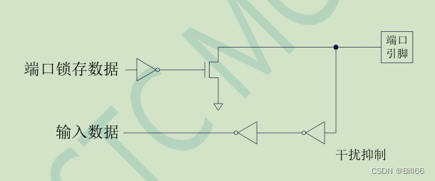
2. Under different working modes I/O chart
STC32G Quasi bidirectional of Series MCU I/O Structure diagram is as follows :

STC32G Push pull output of Series MCU I/O Structure diagram is as follows :

STC32G High resistance input of Series MCU I/O Structure diagram is as follows :

STC32G Leakage opening of series single chip microcomputer I/O Structure diagram is as follows :
STC32G Series single chip microcomputer is relative to STC8 position 8051 SCM added 4.1K Pull up the resistance on 10K Pull down resistance , as follows :

4. Library function STC The official website provides STC32G The latest library function of is 4 edition , The date of issue is 2022 year 6 month 9 Number . Download after decompression , stay library The files visible under the folder are as follows :
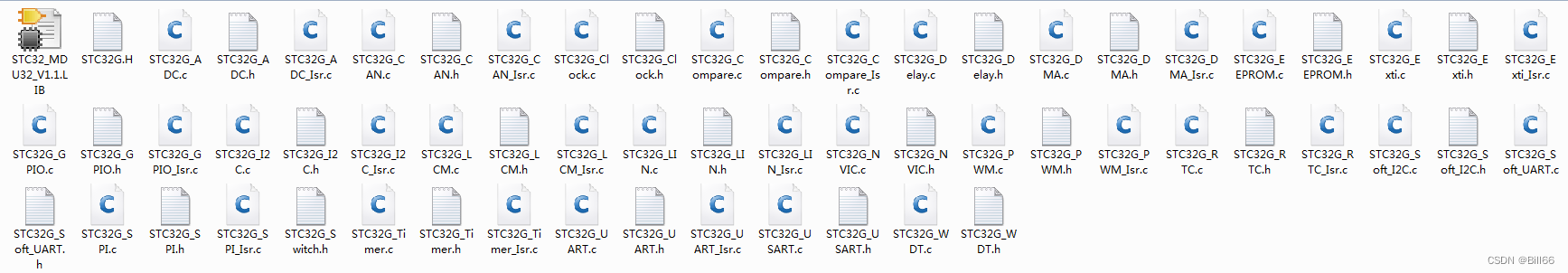
among STC32G_GPIO.h The code for is as follows :
/*---------------------------------------------------------------------*/
/* --- STC MCU Limited ------------------------------------------------*/
/* --- STC 1T Series MCU Demo Programme -------------------------------*/
/* --- Mobile: (86)13922805190 ----------------------------------------*/
/* --- Fax: 86-0513-55012956,55012947,55012969 ------------------------*/
/* --- Tel: 86-0513-55012928,55012929,55012966 ------------------------*/
/* --- Web: www.STCMCU.com --------------------------------------------*/
/* --- Web: www.STCMCUDATA.com  ---------------------------------------*/
/* --- QQ:  800003751 -------------------------------------------------*/
/*  If you want to use... In this program , Please indicate in the procedure that the STC Information and procedures             */
/*---------------------------------------------------------------------*/

#ifndef	__STC32G_GPIO_H
#define	__STC32G_GPIO_H

#include "config.h"

//========================================================================
//                             Port mode settings
//========================================================================
// Quasi two-way port
#define  P0_MODE_IO_PU(Pin)				{P0M1 &= ~(Pin), P0M0 &= ~(Pin);}
#define  P1_MODE_IO_PU(Pin)				{P1M1 &= ~(Pin), P1M0 &= ~(Pin);}
#define  P2_MODE_IO_PU(Pin)				{P2M1 &= ~(Pin), P2M0 &= ~(Pin);}
#define  P3_MODE_IO_PU(Pin)				{P3M1 &= ~(Pin), P3M0 &= ~(Pin);}
#define  P4_MODE_IO_PU(Pin)				{P4M1 &= ~(Pin), P4M0 &= ~(Pin);}
#define  P5_MODE_IO_PU(Pin)				{P5M1 &= ~(Pin), P5M0 &= ~(Pin);}
#define  P6_MODE_IO_PU(Pin)				{P6M1 &= ~(Pin), P6M0 &= ~(Pin);}
#define  P7_MODE_IO_PU(Pin)				{P7M1 &= ~(Pin), P7M0 &= ~(Pin);}
// High impedance input
#define  P0_MODE_IN_HIZ(Pin)			{P0M1 |= (Pin), P0M0 &= ~(Pin);}
#define  P1_MODE_IN_HIZ(Pin)			{P1M1 |= (Pin), P1M0 &= ~(Pin);}
#define  P2_MODE_IN_HIZ(Pin)			{P2M1 |= (Pin), P2M0 &= ~(Pin);}
#define  P3_MODE_IN_HIZ(Pin)			{P3M1 |= (Pin), P3M0 &= ~(Pin);}
#define  P4_MODE_IN_HIZ(Pin)			{P4M1 |= (Pin), P4M0 &= ~(Pin);}
#define  P5_MODE_IN_HIZ(Pin)			{P5M1 |= (Pin), P5M0 &= ~(Pin);}
#define  P6_MODE_IN_HIZ(Pin)			{P6M1 |= (Pin), P6M0 &= ~(Pin);}
#define  P7_MODE_IN_HIZ(Pin)			{P7M1 |= (Pin), P7M0 &= ~(Pin);}
// Open drain
#define  P0_MODE_OUT_OD(Pin)			{P0M1 |= (Pin), P0M0 |= (Pin);}
#define  P1_MODE_OUT_OD(Pin)			{P1M1 |= (Pin), P1M0 |= (Pin);}
#define  P2_MODE_OUT_OD(Pin)			{P2M1 |= (Pin), P2M0 |= (Pin);}
#define  P3_MODE_OUT_OD(Pin)			{P3M1 |= (Pin), P3M0 |= (Pin);}
#define  P4_MODE_OUT_OD(Pin)			{P4M1 |= (Pin), P4M0 |= (Pin);}
#define  P5_MODE_OUT_OD(Pin)			{P5M1 |= (Pin), P5M0 |= (Pin);}
#define  P6_MODE_OUT_OD(Pin)			{P6M1 |= (Pin), P6M0 |= (Pin);}
#define  P7_MODE_OUT_OD(Pin)			{P7M1 |= (Pin), P7M0 |= (Pin);}
// Push pull output
#define  P0_MODE_OUT_PP(Pin)			{P0M1 &= ~(Pin), P0M0 |= (Pin);}
#define  P1_MODE_OUT_PP(Pin)			{P1M1 &= ~(Pin), P1M0 |= (Pin);}
#define  P2_MODE_OUT_PP(Pin)			{P2M1 &= ~(Pin), P2M0 |= (Pin);}
#define  P3_MODE_OUT_PP(Pin)			{P3M1 &= ~(Pin), P3M0 |= (Pin);}
#define  P4_MODE_OUT_PP(Pin)			{P4M1 &= ~(Pin), P4M0 |= (Pin);}
#define  P5_MODE_OUT_PP(Pin)			{P5M1 &= ~(Pin), P5M0 |= (Pin);}
#define  P6_MODE_OUT_PP(Pin)			{P6M1 &= ~(Pin), P6M0 |= (Pin);}
#define  P7_MODE_OUT_PP(Pin)			{P7M1 &= ~(Pin), P7M0 |= (Pin);}

//========================================================================
//                          Port internal 4.1K Pull up settings
//========================================================================
// Pull up enable
#define P0_PULL_UP_ENABLE(Pin)		P0PU |= (Pin)
#define P1_PULL_UP_ENABLE(Pin)		P1PU |= (Pin)
#define P2_PULL_UP_ENABLE(Pin)		P2PU |= (Pin)
#define P3_PULL_UP_ENABLE(Pin)		P3PU |= (Pin)
#define P4_PULL_UP_ENABLE(Pin)		P4PU |= (Pin)
#define P5_PULL_UP_ENABLE(Pin)		P5PU |= (Pin)
#define P6_PULL_UP_ENABLE(Pin)		P6PU |= (Pin)
#define P7_PULL_UP_ENABLE(Pin)		P7PU |= (Pin)
// Pull up forbidden
#define P0_PULL_UP_DISABLE(Pin)		P0PU &= ~(Pin)
#define P1_PULL_UP_DISABLE(Pin)		P1PU &= ~(Pin)
#define P2_PULL_UP_DISABLE(Pin)		P2PU &= ~(Pin)
#define P3_PULL_UP_DISABLE(Pin)		P3PU &= ~(Pin)
#define P4_PULL_UP_DISABLE(Pin)		P4PU &= ~(Pin)
#define P5_PULL_UP_DISABLE(Pin)		P5PU &= ~(Pin)
#define P6_PULL_UP_DISABLE(Pin)		P6PU &= ~(Pin)
#define P7_PULL_UP_DISABLE(Pin)		P7PU &= ~(Pin)

//========================================================================
//                            Port Schmidt trigger setting
//========================================================================
// Schmidt trigger enable
#define P0_ST_ENABLE(Pin)					P0NCS &= ~(Pin)
#define P1_ST_ENABLE(Pin)					P1NCS &= ~(Pin)
#define P2_ST_ENABLE(Pin)					P2NCS &= ~(Pin)
#define P3_ST_ENABLE(Pin)					P3NCS &= ~(Pin)
#define P4_ST_ENABLE(Pin)					P4NCS &= ~(Pin)
#define P5_ST_ENABLE(Pin)					P5NCS &= ~(Pin)
#define P6_ST_ENABLE(Pin)					P6NCS &= ~(Pin)
#define P7_ST_ENABLE(Pin)					P7NCS &= ~(Pin)
// Schmidt trigger inhibit
#define P0_ST_DISABLE(Pin)				P0NCS |= (Pin)
#define P1_ST_DISABLE(Pin)				P1NCS |= (Pin)
#define P2_ST_DISABLE(Pin)				P2NCS |= (Pin)
#define P3_ST_DISABLE(Pin)				P3NCS |= (Pin)
#define P4_ST_DISABLE(Pin)				P4NCS |= (Pin)
#define P5_ST_DISABLE(Pin)				P5NCS |= (Pin)
#define P6_ST_DISABLE(Pin)				P6NCS |= (Pin)
#define P7_ST_DISABLE(Pin)				P7NCS |= (Pin)

//========================================================================
//                           Port level conversion speed setting
//========================================================================
// Level conversion is slow , The corresponding up and down rush is relatively small
#define P0_SPEED_LOW(Pin)					P0SR |= (Pin)
#define P1_SPEED_LOW(Pin)					P1SR |= (Pin)
#define P2_SPEED_LOW(Pin)					P2SR |= (Pin)
#define P3_SPEED_LOW(Pin)					P3SR |= (Pin)
#define P4_SPEED_LOW(Pin)					P4SR |= (Pin)
#define P5_SPEED_LOW(Pin)					P5SR |= (Pin)
#define P6_SPEED_LOW(Pin)					P6SR |= (Pin)
#define P7_SPEED_LOW(Pin)					P7SR |= (Pin)
// Fast level conversion , The corresponding up and down rush is relatively large
#define P0_SPEED_HIGH(Pin)				P0SR &= ~(Pin)
#define P1_SPEED_HIGH(Pin)				P1SR &= ~(Pin)
#define P2_SPEED_HIGH(Pin)				P2SR &= ~(Pin)
#define P3_SPEED_HIGH(Pin)				P3SR &= ~(Pin)
#define P4_SPEED_HIGH(Pin)				P4SR &= ~(Pin)
#define P5_SPEED_HIGH(Pin)				P5SR &= ~(Pin)
#define P6_SPEED_HIGH(Pin)				P6SR &= ~(Pin)
#define P7_SPEED_HIGH(Pin)				P7SR &= ~(Pin)

//========================================================================
//                           Port drive current control settings
//========================================================================
// General drive capability
#define P0_DRIVE_MEDIUM(Pin)			P0DR |= (Pin)
#define P1_DRIVE_MEDIUM(Pin)			P1DR |= (Pin)
#define P2_DRIVE_MEDIUM(Pin)			P2DR |= (Pin)
#define P3_DRIVE_MEDIUM(Pin)			P3DR |= (Pin)
#define P4_DRIVE_MEDIUM(Pin)			P4DR |= (Pin)
#define P5_DRIVE_MEDIUM(Pin)			P5DR |= (Pin)
#define P6_DRIVE_MEDIUM(Pin)			P6DR |= (Pin)
#define P7_DRIVE_MEDIUM(Pin)			P7DR |= (Pin)
// Enhance driving capability
#define P0_DRIVE_HIGH(Pin)				P0DR &= ~(Pin)
#define P1_DRIVE_HIGH(Pin)				P1DR &= ~(Pin)
#define P2_DRIVE_HIGH(Pin)				P2DR &= ~(Pin)
#define P3_DRIVE_HIGH(Pin)				P3DR &= ~(Pin)
#define P4_DRIVE_HIGH(Pin)				P4DR &= ~(Pin)
#define P5_DRIVE_HIGH(Pin)				P5DR &= ~(Pin)
#define P6_DRIVE_HIGH(Pin)				P6DR &= ~(Pin)
#define P7_DRIVE_HIGH(Pin)				P7DR &= ~(Pin)

//========================================================================
//                           Port digital signal input enable
//========================================================================
// Enable digital signal input
#define P0_DIGIT_IN_ENABLE(Pin)		P0IE |= (Pin)
#define P1_DIGIT_IN_ENABLE(Pin)		P1IE |= (Pin)
#define P2_DIGIT_IN_ENABLE(Pin)		P2IE |= (Pin)
#define P3_DIGIT_IN_ENABLE(Pin)		P3IE |= (Pin)
#define P4_DIGIT_IN_ENABLE(Pin)		P4IE |= (Pin)
#define P5_DIGIT_IN_ENABLE(Pin)		P5IE |= (Pin)
#define P6_DIGIT_IN_ENABLE(Pin)		P6IE |= (Pin)
#define P7_DIGIT_IN_ENABLE(Pin)		P7IE |= (Pin)
// Prohibit digital signal input
#define P0_DIGIT_IN_DISABLE(Pin)	P0IE &= ~(Pin)
#define P1_DIGIT_IN_DISABLE(Pin)	P1IE &= ~(Pin)
#define P2_DIGIT_IN_DISABLE(Pin)	P2IE &= ~(Pin)
#define P3_DIGIT_IN_DISABLE(Pin)	P3IE &= ~(Pin)
#define P4_DIGIT_IN_DISABLE(Pin)	P4IE &= ~(Pin)
#define P5_DIGIT_IN_DISABLE(Pin)	P5IE &= ~(Pin)
#define P6_DIGIT_IN_DISABLE(Pin)	P6IE &= ~(Pin)
#define P7_DIGIT_IN_DISABLE(Pin)	P7IE &= ~(Pin)

//========================================================================
//                               Definition statement
//========================================================================

#define	GPIO_PullUp		0	// Pull up the quasi two-way opening
#define	GPIO_HighZ		1	// Floating input
#define	GPIO_OUT_OD		2	// Open drain output
#define	GPIO_OUT_PP		3	// Push pull output

#define	GPIO_Pin_0		0x01	//IO Pin  Px.0
#define	GPIO_Pin_1		0x02	//IO Pin  Px.1
#define	GPIO_Pin_2		0x04	//IO Pin  Px.2
#define	GPIO_Pin_3		0x08	//IO Pin  Px.3
#define	GPIO_Pin_4		0x10	//IO Pin  Px.4
#define	GPIO_Pin_5		0x20	//IO Pin  Px.5
#define	GPIO_Pin_6		0x40	//IO Pin  Px.6
#define	GPIO_Pin_7		0x80	//IO Pin  Px.7
#define	GPIO_Pin_LOW	0x0F	//IO low 4 Bit pin
#define	GPIO_Pin_HIGH	0xF0	//IO high 4 Bit pin
#define	GPIO_Pin_All	0xFF	//IO All pins

#define	GPIO_P0			0		//
#define	GPIO_P1			1
#define	GPIO_P2			2
#define	GPIO_P3			3
#define	GPIO_P4			4
#define	GPIO_P5			5
#define	GPIO_P6			6
#define	GPIO_P7			7


typedef struct
{
	u8	Mode;		//IO Pattern ,  		GPIO_PullUp,GPIO_HighZ,GPIO_OUT_OD,GPIO_OUT_PP
	u8	Pin;		// Port to set
} GPIO_InitTypeDef;

u8	GPIO_Inilize(u8 GPIO, GPIO_InitTypeDef *GPIOx);

#endif
STC32G_GPIO.c The code in is as follows :
/*---------------------------------------------------------------------*/
/* --- STC MCU Limited ------------------------------------------------*/
/* --- STC 1T Series MCU Demo Programme -------------------------------*/
/* --- Mobile: (86)13922805190 ----------------------------------------*/
/* --- Fax: 86-0513-55012956,55012947,55012969 ------------------------*/
/* --- Tel: 86-0513-55012928,55012929,55012966 ------------------------*/
/* --- Web: www.STCMCU.com --------------------------------------------*/
/* --- Web: www.STCMCUDATA.com  ---------------------------------------*/
/* --- QQ:  800003751 -------------------------------------------------*/
/*  If you want to use... In this program , Please indicate in the procedure that the STC Information and procedures             */
/*---------------------------------------------------------------------*/

#include	"STC32G_GPIO.h"

//========================================================================
//  function : u8	GPIO_Inilize(u8 GPIO, GPIO_InitTypeDef *GPIOx)
//  describe :  initialization IO mouth .
//  Parameters : GPIOx:  Structural parameters , Please refer to timer.h Definition in .
//  return :  Successfully returns  SUCCESS,  Erroneous return  FAIL.
//  edition : V1.0, 2012-10-22
//========================================================================
u8	GPIO_Inilize(u8 GPIO, GPIO_InitTypeDef *GPIOx)
{
	if(GPIO > GPIO_P7)				return FAIL;	// error
	if(GPIOx->Mode > GPIO_OUT_PP)	return FAIL;	// error
	if(GPIO == GPIO_P0)
	{
		if(GPIOx->Mode == GPIO_PullUp)		P0M1 &= ~GPIOx->Pin,	P0M0 &= ~GPIOx->Pin;	 // Pull up the quasi two-way opening
		if(GPIOx->Mode == GPIO_HighZ)			P0M1 |=  GPIOx->Pin,	P0M0 &= ~GPIOx->Pin;	 // Floating input
		if(GPIOx->Mode == GPIO_OUT_OD)		P0M1 |=  GPIOx->Pin,	P0M0 |=  GPIOx->Pin;	 // Open drain output
		if(GPIOx->Mode == GPIO_OUT_PP)		P0M1 &= ~GPIOx->Pin,	P0M0 |=  GPIOx->Pin;	 // Push pull output
	}
	if(GPIO == GPIO_P1)
	{
		if(GPIOx->Mode == GPIO_PullUp)		P1M1 &= ~GPIOx->Pin,	P1M0 &= ~GPIOx->Pin;	 // Pull up the quasi two-way opening
		if(GPIOx->Mode == GPIO_HighZ)			P1M1 |=  GPIOx->Pin,	P1M0 &= ~GPIOx->Pin;	 // Floating input
		if(GPIOx->Mode == GPIO_OUT_OD)		P1M1 |=  GPIOx->Pin,	P1M0 |=  GPIOx->Pin;	 // Open drain output
		if(GPIOx->Mode == GPIO_OUT_PP)		P1M1 &= ~GPIOx->Pin,	P1M0 |=  GPIOx->Pin;	 // Push pull output
	}
	if(GPIO == GPIO_P2)
	{
		if(GPIOx->Mode == GPIO_PullUp)		P2M1 &= ~GPIOx->Pin,	P2M0 &= ~GPIOx->Pin;	 // Pull up the quasi two-way opening
		if(GPIOx->Mode == GPIO_HighZ)			P2M1 |=  GPIOx->Pin,	P2M0 &= ~GPIOx->Pin;	 // Floating input
		if(GPIOx->Mode == GPIO_OUT_OD)		P2M1 |=  GPIOx->Pin,	P2M0 |=  GPIOx->Pin;	 // Open drain output
		if(GPIOx->Mode == GPIO_OUT_PP)		P2M1 &= ~GPIOx->Pin,	P2M0 |=  GPIOx->Pin;	 // Push pull output
	}
	if(GPIO == GPIO_P3)
	{
		if(GPIOx->Mode == GPIO_PullUp)		P3M1 &= ~GPIOx->Pin,	P3M0 &= ~GPIOx->Pin;	 // Pull up the quasi two-way opening
		if(GPIOx->Mode == GPIO_HighZ)			P3M1 |=  GPIOx->Pin,	P3M0 &= ~GPIOx->Pin;	 // Floating input
		if(GPIOx->Mode == GPIO_OUT_OD)		P3M1 |=  GPIOx->Pin,	P3M0 |=  GPIOx->Pin;	 // Open drain output
		if(GPIOx->Mode == GPIO_OUT_PP)		P3M1 &= ~GPIOx->Pin,	P3M0 |=  GPIOx->Pin;	 // Push pull output
	}
	if(GPIO == GPIO_P4)
	{
		if(GPIOx->Mode == GPIO_PullUp)		P4M1 &= ~GPIOx->Pin,	P4M0 &= ~GPIOx->Pin;	 // Pull up the quasi two-way opening
		if(GPIOx->Mode == GPIO_HighZ)			P4M1 |=  GPIOx->Pin,	P4M0 &= ~GPIOx->Pin;	 // Floating input
		if(GPIOx->Mode == GPIO_OUT_OD)		P4M1 |=  GPIOx->Pin,	P4M0 |=  GPIOx->Pin;	 // Open drain output
		if(GPIOx->Mode == GPIO_OUT_PP)		P4M1 &= ~GPIOx->Pin,	P4M0 |=  GPIOx->Pin;	 // Push pull output
	}
	if(GPIO == GPIO_P5)
	{
		if(GPIOx->Mode == GPIO_PullUp)		P5M1 &= ~GPIOx->Pin,	P5M0 &= ~GPIOx->Pin;	 // Pull up the quasi two-way opening
		if(GPIOx->Mode == GPIO_HighZ)			P5M1 |=  GPIOx->Pin,	P5M0 &= ~GPIOx->Pin;	 // Floating input
		if(GPIOx->Mode == GPIO_OUT_OD)		P5M1 |=  GPIOx->Pin,	P5M0 |=  GPIOx->Pin;	 // Open drain output
		if(GPIOx->Mode == GPIO_OUT_PP)		P5M1 &= ~GPIOx->Pin,	P5M0 |=  GPIOx->Pin;	 // Push pull output
	}
	if(GPIO == GPIO_P6)
	{
		if(GPIOx->Mode == GPIO_PullUp)		P6M1 &= ~GPIOx->Pin,	P6M0 &= ~GPIOx->Pin;	 // Pull up the quasi two-way opening
		if(GPIOx->Mode == GPIO_HighZ)			P6M1 |=  GPIOx->Pin,	P6M0 &= ~GPIOx->Pin;	 // Floating input
		if(GPIOx->Mode == GPIO_OUT_OD)		P6M1 |=  GPIOx->Pin,	P6M0 |=  GPIOx->Pin;	 // Open drain output
		if(GPIOx->Mode == GPIO_OUT_PP)		P6M1 &= ~GPIOx->Pin,	P6M0 |=  GPIOx->Pin;	 // Push pull output
	}
	if(GPIO == GPIO_P7)
	{
		if(GPIOx->Mode == GPIO_PullUp)		P7M1 &= ~GPIOx->Pin,	P7M0 &= ~GPIOx->Pin;	 // Pull up the quasi two-way opening
		if(GPIOx->Mode == GPIO_HighZ)			P7M1 |=  GPIOx->Pin,	P7M0 &= ~GPIOx->Pin;	 // Floating input
		if(GPIOx->Mode == GPIO_OUT_OD)		P7M1 |=  GPIOx->Pin,	P7M0 |=  GPIOx->Pin;	 // Open drain output
		if(GPIOx->Mode == GPIO_OUT_PP)		P7M1 &= ~GPIOx->Pin,	P7M0 |=  GPIOx->Pin;	 // Push pull output
	}
	return SUCCESS;	// success
}
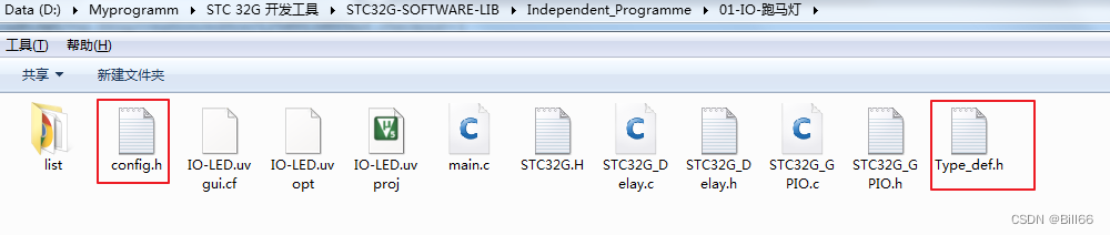
Be careful STC32G_GPIO.h Contains header files config.h And custom data type symbols , Need from Independent_Programme The following two header files will be in the subdirectory under the folder Copy To library Under the folder , Otherwise the compilation will report an error .
The following is the library function I wrote myself , The header file is as follows :
/*STC32G_GPIO.h
Designed by Bill Liu
Version 0.0
Modified last by Bill Liu on 06/23/2022
*/
#ifndef __STC32G_GPIO_H
#define __STC32G_GPIO_H
#include <STC32G.h>
#include "config.h"
#include "mtype.h"
//***************************************
typedef enum
{
PIN0 = 0x01,
PIN1 = 0x02,
PIN2 = 0x04,
PIN3 = 0x08,
PIN4 = 0x10,
PIN5 = 0x20,
PIN6 = 0x40,
PIN7 = 0x80
}IOPORT_PIN;
//***************************************
typedef enum
{
SCT_P0 = 0x01, //P0 port
SCT_P1 = 0x02, //P1 port
SCT_P2 = 0x04, //P2 port
SCT_P3 = 0x08, //P3 port
SCT_P4 = 0x10, //P4 port
SCT_P5 = 0x20, //P5 port
SCT_P6 = 0x40, //P6 port
SCT_P7 = 0x80 //P7 port
}STC32G_IOPORT;
//***************************************
typedef enum
{
BI_IO = 0, //bidirectional I/O
PP_OUT, //push_pull out
HI_IN, //high impendence in
ODR_OUT //open drain out
}STC32G_IOMODE;
/****************************************
Function: STC32G_P0PinsInit(ui8 pins, STC32G_IOMODE mode, BOOL pullUpEnable, BOOL pullDownEnable,BOOL drvEn,BOOL speedHi,BOOL dIEnable, BOOL sTEnable);
Return value: void
pins: pins to init,
mode: configure work mode
pullUpEnable: 0-pullup disable, 1-pull up enable
pullDownEnable: 0-pull down disable,1-pull down enable
drvEn: 1-drive ability enhance enable, 0-drive ability enhance disable
speedHi; 1- I/O speed high enable, 0- I/O speed high disable
dIEnable: 1- digital singal input enable, 0- digital singal input enable
sTEnable: 1-schmitt trigger enable, 0-schmitt trigger disable
Example:
STC32G_P0PinsInit(PIN0|PIN3, BI_IO, 0, 0,0,1,1,1);
****************************************/
void STC32G_P0PinsInit(ui8 pins, STC32G_IOMODE mode, BOOL pullUpEnable, BOOL pullDownEnable,BOOL drvEn,BOOL speedHi,BOOL dIEnable, BOOL sTEnable);
/****************************************
Function: STC32G_P1PinsInit(ui8 pins, STC32G_IOMODE mode, BOOL pullUpEnable, BOOL pullDownEnable,BOOL drvEn,BOOL speedHi,BOOL dIEnable, BOOL sTEnable);
Return value: void
pins: pins to init,
mode: configure work mode
pullUpEnable: 0-pullup disable, 1-pull up enable
pullDownEnable: 0-pull down disable,1-pull down enable
drvEn: 1-drive ability enhance enable, 0-drive ability enhance disable
speedHi; 1- I/O speed high enable, 0- I/O speed high disable
dIEnable: 1- digital singal input enable, 0- digital singal input enable
sTEnable: 1-schmitt trigger enable, 0-schmitt trigger disable
Example:
STC32G_P1PinsInit(PIN0|PIN3, BI_IO, 0, 0,0,1,1,1);
****************************************/
void STC32G_P1PinsInit(ui8 pins, STC32G_IOMODE mode, BOOL pullUpEnable, BOOL pullDownEnable,BOOL drvEn,BOOL speedHi,BOOL dIEnable, BOOL sTEnable);
/****************************************
Function: STC32G_P2PinsInit(ui8 pins, STC32G_IOMODE mode, BOOL pullUpEnable, BOOL pullDownEnable,BOOL drvEn,BOOL speedHi,BOOL dIEnable, BOOL sTEnable);
Return value: void
pins: pins to init,
mode: configure work mode
pullUpEnable: 0-pullup disable, 1-pull up enable
pullDownEnable: 0-pull down disable,1-pull down enable
drvEn: 1-drive ability enhance enable, 0-drive ability enhance disable
speedHi; 1- I/O speed high enable, 0- I/O speed high disable
dIEnable: 1- digital singal input enable, 0- digital singal input enable
sTEnable: 1-schmitt trigger enable, 0-schmitt trigger disable
Example:
STC32G_P2PinsInit(PIN0|PIN3, BI_IO, 0, 0,0,1,1,1);
****************************************/
void STC32G_P2PinsInit(ui8 pins, STC32G_IOMODE mode, BOOL pullUpEnable, BOOL pullDownEnable,BOOL drvEn,BOOL speedHi,BOOL dIEnable, BOOL sTEnable);
/****************************************
Function: STC32G_P3PinsInit(ui8 pins, STC32G_IOMODE mode, BOOL pullUpEnable, BOOL pullDownEnable,BOOL drvEn,BOOL speedHi,BOOL dIEnable, BOOL sTEnable);
Return value: void
pins: pins to init,
mode: configure work mode
pullUpEnable: 0-pullup disable, 1-pull up enable
pullDownEnable: 0-pull down disable,1-pull down enable
drvEn: 1-drive ability enhance enable, 0-drive ability enhance disable
speedHi; 1- I/O speed high enable, 0- I/O speed high disable
dIEnable: 1- digital singal input enable, 0- digital singal input enable
sTEnable: 1-schmitt trigger enable, 0-schmitt trigger disable
Example:
STC32G_P3PinsInit(PIN0|PIN3, BI_IO, 0, 0,0,1,1,1);
****************************************/
void STC32G_P3PinsInit(ui8 pins, STC32G_IOMODE mode, BOOL pullUpEnable, BOOL pullDownEnable,BOOL drvEn,BOOL speedHi,BOOL dIEnable, BOOL sTEnable);
/****************************************
Function: STC32G_P4PinsInit(ui8 pins, STC32G_IOMODE mode, BOOL pullUpEnable, BOOL pullDownEnable,BOOL drvEn,BOOL speedHi,BOOL dIEnable, BOOL sTEnable);
Return value: void
pins: pins to init,
mode: configure work mode
pullUpEnable: 0-pullup disable, 1-pull up enable
pullDownEnable: 0-pull down disable,1-pull down enable
drvEn: 1-drive ability enhance enable, 0-drive ability enhance disable
speedHi; 1- I/O speed high enable, 0- I/O speed high disable
dIEnable: 1- digital singal input enable, 0- digital singal input enable
sTEnable: 1-schmitt trigger enable, 0-schmitt trigger disable
Example:
STC32G_P4PinsInit(PIN0|PIN3, BI_IO, 0, 0,0,1,1,1);
****************************************/
void STC32G_P4PinsInit(ui8 pins, STC32G_IOMODE mode, BOOL pullUpEnable, BOOL pullDownEnable,BOOL drvEn,BOOL speedHi,BOOL dIEnable, BOOL sTEnable);
/****************************************
Function: STC32G_P5PinsInit(ui8 pins, STC32G_IOMODE mode, BOOL pullUpEnable, BOOL pullDownEnable,BOOL drvEn,BOOL speedHi,BOOL dIEnable, BOOL sTEnable);
Return value: void
pins: pins to init,
mode: configure work mode
pullUpEnable: 0-pullup disable, 1-pull up enable
pullDownEnable: 0-pull down disable,1-pull down enable
drvEn: 1-drive ability enhance enable, 0-drive ability enhance disable
speedHi; 1- I/O speed high enable, 0- I/O speed high disable
dIEnable: 1- digital singal input enable, 0- digital singal input enable
sTEnable: 1-schmitt trigger enable, 0-schmitt trigger disable
Example:
STC32G_P5PinsInit(PIN0|PIN3, BI_IO, 0, 0,0,1,1,1);
****************************************/
void STC32G_P5PinsInit(ui8 pins, STC32G_IOMODE mode, BOOL pullUpEnable, BOOL pullDownEnable,BOOL drvEn,BOOL speedHi,BOOL dIEnable, BOOL sTEnable);
/****************************************
Function: STC32G_P6PinsInit(ui8 pins, STC32G_IOMODE mode, BOOL pullUpEnable, BOOL pullDownEnable,BOOL drvEn,BOOL speedHi,BOOL dIEnable, BOOL sTEnable);
Return value: void
pins: pins to init,
mode: configure work mode
pullUpEnable: 0-pullup disable, 1-pull up enable
pullDownEnable: 0-pull down disable,1-pull down enable
drvEn: 1-drive ability enhance enable, 0-drive ability enhance disable
speedHi; 1- I/O speed high enable, 0- I/O speed high disable
dIEnable: 1- digital singal input enable, 0- digital singal input enable
sTEnable: 1-schmitt trigger enable, 0-schmitt trigger disable
Example:
STC32G_P6PinsInit(PIN0|PIN3, BI_IO, 0, 0,0,1,1,1);
****************************************/
void STC32G_P6PinsInit(ui8 pins, STC32G_IOMODE mode, BOOL pullUpEnable, BOOL pullDownEnable,BOOL drvEn,BOOL speedHi,BOOL dIEnable, BOOL sTEnable);
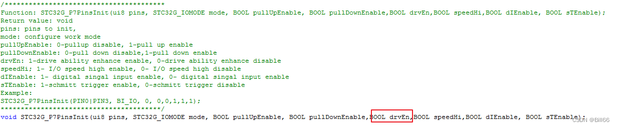
/****************************************
Function: STC32G_P7PinsInit(ui8 pins, STC32G_IOMODE mode, BOOL pullUpEnable, BOOL pullDownEnable,BOOL drvEn,BOOL speedHi,BOOL dIEnable, BOOL sTEnable);
Return value: void
pins: pins to init,
mode: configure work mode
pullUpEnable: 0-pullup disable, 1-pull up enable
pullDownEnable: 0-pull down disable,1-pull down enable
drvEn: 1-drive ability enhance enable, 0-drive ability enhance disable
speedHi; 1- I/O speed high enable, 0- I/O speed high disable
dIEnable: 1- digital singal input enable, 0- digital singal input enable
sTEnable: 1-schmitt trigger enable, 0-schmitt trigger disable
Example:
STC32G_P7PinsInit(PIN0|PIN3, BI_IO, 0, 0,0,1,1,1);
****************************************/
void STC32G_P7PinsInit(ui8 pins, STC32G_IOMODE mode, BOOL pullUpEnable, BOOL pullDownEnable,BOOL drvEn,BOOL speedHi,BOOL dIEnable, BOOL sTEnable);
/****************************************
Function: STC32G_PortsPinsInit(ui8 ports,ui8 pins, STC32G_IOMODE mode, BOOL pullUpEnable, BOOL pullDownEnable,BOOL drvEn,BOOL speedHi,BOOL dIEnable, BOOL sTEnable);
Return value: void
ports: ports to init
pins: pins to init,
mode: configure work mode
pullUpEnable: 0-pullup disable, 1-pull up enable
pullDownEnable: 0-pull down disable,1-pull down enable
drvEn: 1-drive ability enhance enable, 0-drive ability enhance disable
speedHi; 1- I/O speed high enable, 0- I/O speed high disable
dIEnable: 1- digital singal input enable, 0- digital singal input enable
sTEnable: 1-schmitt trigger enable, 0-schmitt trigger disable
Example:
STC32G_PortsPinsInit(SCT_P0|SCT_P1|SCT_P6,PIN0|PIN3, BI_IO, 0, 0,0,1,1,1);
****************************************/
void STC32G_PortsPinsInit(ui8 ports,ui8 pins, STC32G_IOMODE mode, BOOL pullUpEnable, BOOL pullDownEnable,BOOL drvEn,BOOL speedHi,BOOL dIEnable, BOOL sTEnable);
#endifThe source code of the library function is as follows :
/*STC32G_GPIO.h
  Designed by Bill Liu
  Version 0.0
  Modified last by Bill Liu on 06/23/2022
*/

#include	"STC32G_GPIO.h"

//*********************************************************************************************************************************************/
void STC32G_P0PinsInit(ui8 pins, STC32G_IOMODE mode, BOOL pullUpEnable, BOOL pullDownEnable,BOOL drvEn,BOOL speedHi,BOOL dIEnable, BOOL sTEnable)
{
	SysInit();
	switch(mode)
	{
		case BI_IO:
			P0M1 &= ~pins;
			P0M0 &= ~pins;
			break;
		case PP_OUT:
			P0M1 &= ~pins;
			P0M0 |= pins;
			break;
		case HI_IN:
			P0M1 |= pins;
			P0M0 &= pins;
			break;
		case ODR_OUT:
			P0M1 |= pins;
			P0M0 |= pins;
			break;
	}
	if(pullUpEnable)
		P0PU |= pins;
	else
		P0PU &= ~pins;
	if(pullDownEnable)
		P0DR |= pins;
	else
		P0DR &= ~pins;
	if(drvEn)
		P0DR &= ~pins;
	else
		P0DR |= pins;
	if(speedHi)
		P0SR &= ~pins;
	else
		P0SR |= pins;
	if(dIEnable)
		P0IE |= pins;
	else
		P0IE &= ~pins;
	if(sTEnable)
		P0NCS &= ~pins;
	else
		P0NCS |= pins;
}
//End of STC32G_P0PinsInit(ui8 pins, STC32G_IOMODE mode, BOOL pullUpEnable, BOOL pullDownEnable,BOOL drvEn,BOOL speedHi,BOOL dIEnable, BOOL sTEnable)

//*********************************************************************************************************************************************/
void STC32G_P1PinsInit(ui8 pins, STC32G_IOMODE mode, BOOL pullUpEnable, BOOL pullDownEnable,BOOL drvEn,BOOL speedHi,BOOL dIEnable, BOOL sTEnable)
{
	SysInit();
	switch(mode)
	{
		case BI_IO:
			P1M1 &= ~pins;
			P1M0 &= ~pins;
			break;
		case PP_OUT:
			P1M1 &= ~pins;
			P1M0 |= pins;
			break;
		case HI_IN:
			P1M1 |= pins;
			P1M0 &= pins;
			break;
		case ODR_OUT:
			P1M1 |= pins;
			P1M0 |= pins;
			break;
	}
	if(pullUpEnable)
		P1PU |= pins;
	else
		P1PU &= ~pins;
	if(pullDownEnable)
		P1DR |= pins;
	else
		P1DR &= ~pins;
	if(drvEn)
		P1DR &= ~pins;
	else
		P1DR |= pins;
	if(speedHi)
		P1SR &= ~pins;
	else
		P1SR |= pins;
	if(dIEnable)
		P1IE |= pins;
	else
		P1IE &= ~pins;
	if(sTEnable)
		P1NCS &= ~pins;
	else
		P1NCS |= pins;
}
//End of STC32G_P1PinsInit(ui8 pins, STC32G_IOMODE mode, BOOL pullUpEnable, BOOL pullDownEnable,BOOL drvEn,BOOL speedHi,BOOL dIEnable, BOOL sTEnable)

//**********************************************************************************************************************************************/
void STC32G_P2PinsInit(ui8 pins, STC32G_IOMODE mode, BOOL pullUpEnable, BOOL pullDownEnable,BOOL drvEn,BOOL speedHi,BOOL dIEnable, BOOL sTEnable)
{
	SysInit();
	switch(mode)
	{
		case BI_IO:
			P2M1 &= ~pins;
			P2M0 &= ~pins;
			break;
		case PP_OUT:
			P2M1 &= ~pins;
			P2M0 |= pins;
			break;
		case HI_IN:
			P2M1 |= pins;
			P2M0 &= pins;
			break;
		case ODR_OUT:
			P2M1 |= pins;
			P2M0 |= pins;
			break;
	}
	if(pullUpEnable)
		P2PU |= pins;
	else
		P2PU &= ~pins;
	if(pullDownEnable)
		P2DR |= pins;
	else
		P2DR &= ~pins;
	if(drvEn)
		P2DR &= ~pins;
	else
		P2DR |= pins;
	if(speedHi)
		P2SR &= ~pins;
	else
		P2SR |= pins;
	if(dIEnable)
		P2IE |= pins;
	else
		P2IE &= ~pins;
	if(sTEnable)
		P2NCS &= ~pins;
	else
		P2NCS |= pins;
}
//End of STC32G_P2PinsInit(ui8 pins, STC32G_IOMODE mode, BOOL pullUpEnable, BOOL pullDownEnable,BOOL drvEn,BOOL speedHi,BOOL dIEnable, BOOL sTEnable)

//*********************************************************************************************************************************************/
void STC32G_P3PinsInit(ui8 pins, STC32G_IOMODE mode, BOOL pullUpEnable, BOOL pullDownEnable,BOOL drvEn,BOOL speedHi,BOOL dIEnable, BOOL sTEnable)
{
	SysInit();
	switch(mode)
	{
		case BI_IO:
			P3M1 &= ~pins;
			P3M0 &= ~pins;
			break;
		case PP_OUT:
			P3M1 &= ~pins;
			P3M0 |= pins;
			break;
		case HI_IN:
			P3M1 |= pins;
			P3M0 &= pins;
			break;
		case ODR_OUT:
			P3M1 |= pins;
			P3M0 |= pins;
			break;
	}
	if(pullUpEnable)
		P3PU |= pins;
	else
		P3PU &= ~pins;
	if(pullDownEnable)
		P3DR |= pins;
	else
		P3DR &= ~pins;
	if(drvEn)
		P3DR &= ~pins;
	else
		P3DR |= pins;
	if(speedHi)
		P3SR &= ~pins;
	else
		P3SR |= pins;
	if(dIEnable)
		P3IE |= pins;
	else
		P3IE &= ~pins;
	if(sTEnable)
		P3NCS &= ~pins;
	else
		P3NCS |= pins;
}
//End of STC32G_P3PinsInit(ui8 pins, STC32G_IOMODE mode, BOOL pullUpEnable, BOOL pullDownEnable,BOOL drvEn,BOOL speedHi,BOOL dIEnable, BOOL sTEnable)

//**********************************************************************************************************************************************/
void STC32G_P4PinsInit(ui8 pins, STC32G_IOMODE mode, BOOL pullUpEnable, BOOL pullDownEnable,BOOL drvEn,BOOL speedHi,BOOL dIEnable, BOOL sTEnable)
{
	SysInit();
	switch(mode)
	{
		case BI_IO:
			P4M1 &= ~pins;
			P4M0 &= ~pins;
			break;
		case PP_OUT:
			P4M1 &= ~pins;
			P4M0 |= pins;
			break;
		case HI_IN:
			P4M1 |= pins;
			P4M0 &= pins;
			break;
		case ODR_OUT:
			P4M1 |= pins;
			P4M0 |= pins;
			break;
	}
	if(pullUpEnable)
		P4PU |= pins;
	else
		P4PU &= ~pins;
	if(pullDownEnable)
		P4DR |= pins;
	else
		P4DR &= ~pins;
	if(drvEn)
		P4DR &= ~pins;
	else
		P4DR |= pins;
	if(speedHi)
		P4SR &= ~pins;
	else
		P4SR |= pins;
	if(dIEnable)
		P4IE |= pins;
	else
		P4IE &= ~pins;
	if(sTEnable)
		P4NCS &= ~pins;
	else
		P4NCS |= pins;
}
//End of STC32G_P4PinsInit(ui8 pins, STC32G_IOMODE mode, BOOL pullUpEnable, BOOL pullDownEnable,BOOL drvEn,BOOL speedHi,BOOL dIEnable, BOOL sTEnable)

//**********************************************************************************************************************************************/
void STC32G_P5PinsInit(ui8 pins, STC32G_IOMODE mode, BOOL pullUpEnable, BOOL pullDownEnable,BOOL drvEn,BOOL speedHi,BOOL dIEnable, BOOL sTEnable)
{
	SysInit();
	switch(mode)
	{
		case BI_IO:
			P5M1 &= ~pins;
			P5M0 &= ~pins;
			break;
		case PP_OUT:
			P5M1 &= ~pins;
			P5M0 |= pins;
			break;
		case HI_IN:
			P5M1 |= pins;
			P5M0 &= pins;
			break;
		case ODR_OUT:
			P5M1 |= pins;
			P5M0 |= pins;
			break;
	}
	if(pullUpEnable)
		P5PU |= pins;
	else
		P5PU &= ~pins;
	if(pullDownEnable)
		P5DR |= pins;
	else
		P5DR &= ~pins;
	if(drvEn)
		P5DR &= ~pins;
	else
		P5DR |= pins;
	if(speedHi)
		P5SR &= ~pins;
	else
		P5SR |= pins;
	if(dIEnable)
		P5IE |= pins;
	else
		P5IE &= ~pins;
	if(sTEnable)
		P5NCS &= ~pins;
	else
		P5NCS |= pins;
}
//End of STC32G_P5PinsInit(ui8 pins, STC32G_IOMODE mode, BOOL pullUpEnable, BOOL pullDownEnable,BOOL drvEn,BOOL speedHi,BOOL dIEnable, BOOL sTEnable)

//**********************************************************************************************************************************************/
void STC32G_P6PinsInit(ui8 pins, STC32G_IOMODE mode, BOOL pullUpEnable, BOOL pullDownEnable,BOOL drvEn,BOOL speedHi,BOOL dIEnable, BOOL sTEnable)
{
	SysInit();
	switch(mode)
	{
		case BI_IO:
			P6M1 &= ~pins;
			P6M0 &= ~pins;
			break;
		case PP_OUT:
			P6M1 &= ~pins;
			P6M0 |= pins;
			break;
		case HI_IN:
			P6M1 |= pins;
			P6M0 &= pins;
			break;
		case ODR_OUT:
			P6M1 |= pins;
			P6M0 |= pins;
			break;
	}
	if(pullUpEnable)
		P6PU |= pins;
	else
		P6PU &= ~pins;
	if(pullDownEnable)
		P6DR |= pins;
	else
		P6DR &= ~pins;
	if(drvEn)
		P6DR &= ~pins;
	else
		P6DR |= pins;
	if(speedHi)
		P6SR &= ~pins;
	else
		P6SR |= pins;
	if(dIEnable)
		P6IE |= pins;
	else
		P6IE &= ~pins;
	if(sTEnable)
		P6NCS &= ~pins;
	else
		P6NCS |= pins;
}
//End of STC32G_P6PinsInit(ui8 pins, STC32G_IOMODE mode, BOOL pullUpEnable, BOOL pullDownEnable,BOOL drvEn,BOOL speedHi,BOOL dIEnable, BOOL sTEnable)

//**********************************************************************************************************************************************/
void STC32G_P7PinsInit(ui8 pins, STC32G_IOMODE mode, BOOL pullUpEnable, BOOL pullDownEnable,BOOL drvEn,BOOL speedHi,BOOL dIEnable, BOOL sTEnable)
{
	SysInit();
	switch(mode)
	{
		case BI_IO:
			P7M1 &= ~pins;
			P7M0 &= ~pins;
			break;
		case PP_OUT:
			P7M1 &= ~pins;
			P7M0 |= pins;
			break;
		case HI_IN:
			P7M1 |= pins;
			P7M0 &= pins;
			break;
		case ODR_OUT:
			P7M1 |= pins;
			P7M0 |= pins;
			break;
	}
	if(pullUpEnable)
		P7PU |= pins;
	else
		P7PU &= ~pins;
	if(pullDownEnable)
		P7DR |= pins;
	else
		P7DR &= ~pins;
	if(drvEn)
		P7DR &= ~pins;
	else
		P7DR |= pins;
	if(speedHi)
		P7SR &= ~pins;
	else
		P7SR |= pins;
	if(dIEnable)
		P7IE |= pins;
	else
		P7IE &= ~pins;
	if(sTEnable)
		P7NCS &= ~pins;
	else
		P7NCS |= pins;
}
//End of STC32G_P7PinsInit(ui8 pins, STC32G_IOMODE mode, BOOL pullUpEnable, BOOL pullDownEnable,BOOL drvEn,BOOL speedHi,BOOL dIEnable, BOOL sTEnable)

/***************************************************************************************************************************************************/
void STC32G_PortsPinsInit(ui8 ports,ui8 pins, STC32G_IOMODE mode, BOOL pullUpEnable, BOOL pullDownEnable,BOOL drvEn,BOOL speedHi,BOOL dIEnable, BOOL sTEnable)
{
	ui8 i;
	for(i = 0; i < 8; i++)
	{
		if(ports & (1 << i))
		{
			switch(i)
			{
				case 0:
					STC32G_P0PinsInit(pins, mode, pullUpEnable, pullDownEnable,drvEn,speedHi,dIEnable, sTEnable);
					break;
				case 1:
					STC32G_P1PinsInit(pins, mode, pullUpEnable, pullDownEnable,drvEn,speedHi,dIEnable, sTEnable);
					break;
				case 2:
					STC32G_P2PinsInit(pins, mode, pullUpEnable, pullDownEnable,drvEn,speedHi,dIEnable, sTEnable);
					break;
				case 3:
					STC32G_P3PinsInit(pins, mode, pullUpEnable, pullDownEnable,drvEn,speedHi,dIEnable, sTEnable);
					break;
				case 4:
					STC32G_P4PinsInit(pins, mode, pullUpEnable, pullDownEnable,drvEn,speedHi,dIEnable, sTEnable);
					break;
				case 5:
					STC32G_P5PinsInit(pins, mode, pullUpEnable, pullDownEnable,drvEn,speedHi,dIEnable, sTEnable);
					break;
				case 6:
					STC32G_P6PinsInit(pins, mode, pullUpEnable, pullDownEnable,drvEn,speedHi,dIEnable, sTEnable);
					break;
				case 7:
					STC32G_P7PinsInit(pins, mode, pullUpEnable, pullDownEnable,drvEn,speedHi,dIEnable, sTEnable);
					break;
			}
		}
	}
}
//End of STC32G_PortsPinsInit(ui8 ports,ui8 pins, STC32G_IOMODE mode, BOOL pullUpEnable, BOOL pullDownEnable,BOOL drvEn,BOOL speedHi,BOOL dIEnable, BOOL sTEnable)
I will also config.h Made modifications , The modified code is as follows :
/*STC32G_GPIO.h
  Designed by Bill Liu
  Version 0.0
  Modified last by Bill Liu on 06/23/2022
*/
#ifndef __CONFIG_H__
#define __CONFIG_H__

#define FOSC                    35000000UL
//#define FOSC                    24000000UL
//#define FOSC                    27000000UL
//#define FOSC                    30000000UL
//#define FOSC                    33177600UL


//********************************************************
void SysInit(); //init System speed  fastest


#endif
config.c The source code is as follows :
/*config.c
Designed by Bill Liu
Version 0.0
Modified last by Bill Liu on 06/22/2022
*/
#include <STC32G.h>
#include "config.h"
//********************************************************
void SysInit() //init System speed fastest
{
EAXFR = 1; //visit XFR enable
CKCON = 0x00; //set outer data bus speed fastest
WTST = 0x00; //CPU wait 0 to run program
}
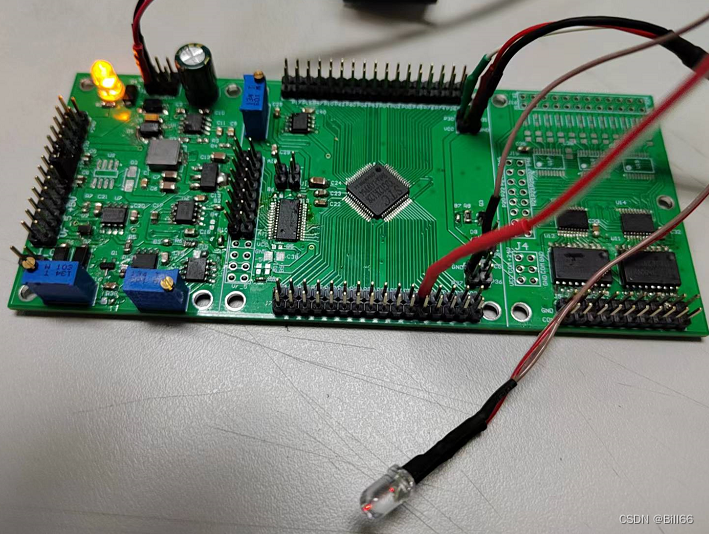
//End of SysInit()5. I/O Configure the instance Next, I will use the library function written by myself to demonstrate the verification I/O To configure . I will use the following board to verify
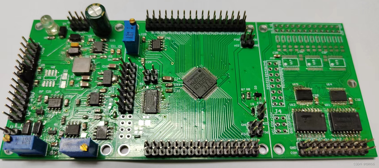
The board is separated by white lines and divided into three areas , On the left is the power area , In the middle are analog sampling and MCU Area , On the right is the logic input and output area . Take another look at the model of single chip microcomputer :
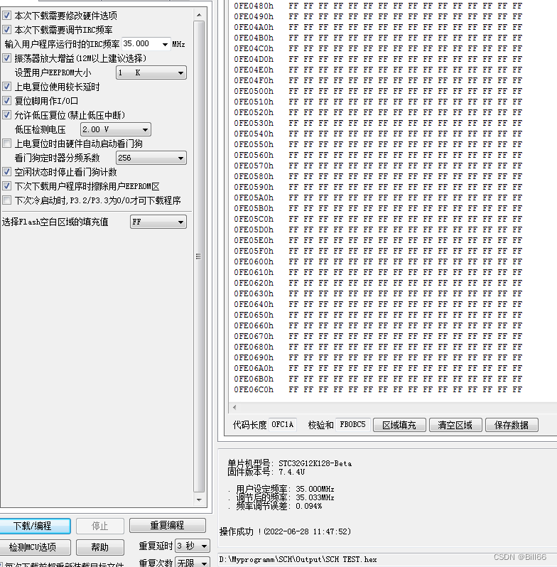
 First compile the following empty program , Download it to the MCU , See if you can succeed .
/*main.c
  Designed by Bill Liu
  Version 0.0
  Modified last by Bill Liu on 06/22/2022
*/

#include "main.h"
#include "config.h"

void main()
{

}
//End of main()
Download successful , as follows :
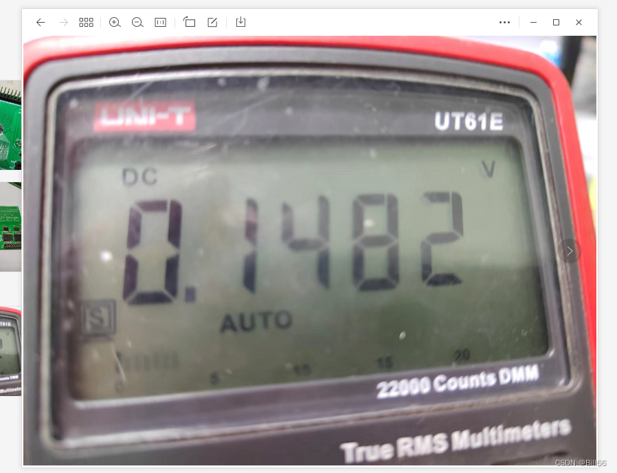
Take a test I/O Output voltage of port , Choose one at will I/O Mouth test ( The actual test is P73), The test results are as follows .
Depending on the output low level , It should output neither high level nor low level ( No current flows , No current flows out ), See if it can drive Led, The following is one that can be lit normally LED:
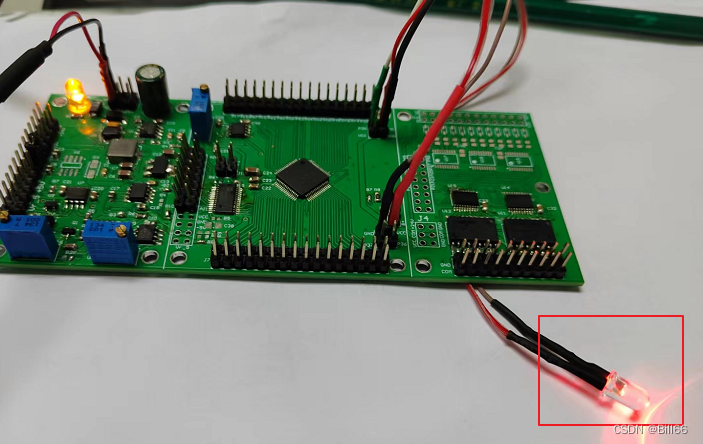
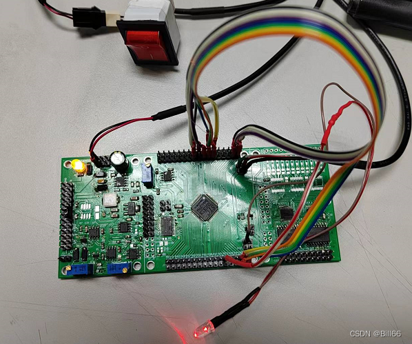
First, keep the power terminal unchanged , Put it on the other end Connect with P73 On the connecting pin , see LED Whether it is lit , give the result as follows :

LED Not lit It indicates that there is no current input .SCT32G Power on reset I/O The port is in the high resistance input state , On the one hand, it can enhance the anti-interference ability , On the other hand, it can avoid the misoperation of the circuit controlled by the single chip microcomputer when it is powered on and reset .
stay main() Insert the following code into the function :
void main()
{
	STC32G_P7PinsInit(PIN3, BI_IO, 0, 0, 0, 0, 0, 0);
	P73 = 0;
	while(1);
}
//End of main()
Compile and download , If the library function is ok ,LED It should light , give the result as follows :
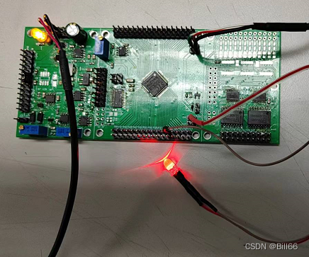
It indicates that there is no error in the library function . take main() The code in the function is modified as follows :
void main()
{
	STC32G_P7PinsInit(PIN3, BI_IO, 0, 0, 0, 0, 0, 0);
	P73 = 1;
	while(1);
}
//End of main()
Compile and download to MCU , Let's test the two-way I/O Weak pull-up positive driving ability . give the result as follows :

LED Only a faint light , explain I/O Weak forward driving ability . Now pull up the resistor to enable , That is, the third parameter of the library function is set to 1, modify main() The code in the function is as follows :
void main()
{
	STC32G_P7PinsInit(PIN3, BI_IO, 1, 0, 0, 0, 0, 0);
	P73 = 1;
	while(1);
}
//End of main()
The results after compiling and downloading are as follows :

LED Brighten , It shows that the forward driving ability has been enhanced . Now increase the driving current , Set the variables in the red box below to 1, Look at the results and changes :
void main()
{
	STC32G_P7PinsInit(PIN3, BI_IO, 0, 0, 1, 0, 0, 0);
	P73 = 1;
	while(1);
}
//End of main()
Compile and download , give the result as follows :
Feeling and two-way I/O The forward driving ability of weak pull-up is similar . Look again. , When the pull-down resistor is turned on, it is bidirectional I/O Weak pull-up positive driving ability . modify main() The function code is as follows :
void main()
{
	STC32G_P7PinsInit(PIN3, BI_IO, 0, 1, 0, 0, 0, 0);
	P73 = 1;
	while(1);
}
//End of main()
The results of compiling and downloading to the MCU are as follows :

Feeling LED The brightness change is not obvious .
STC32G Of I/O a STC15 Of I/O New functions and registers added , As can be seen from the above test ,I/O It has strong negative driving ability ( It can withstand large perfusion current ), Weak forward driving ability , If you want to make I/O The mouth has a large positive driving ability , It needs to be set to push-pull mode , If it is set to bidirectional I/O, It is necessary to pull up the resistor to improve its forward driving ability , Can make PxDR Provide two-way I/O The forward driving ability of is not obvious , Maybe it's just for improving I/O The level conversion speed of is useful .
Let's test it again I/O Read and write , take main() The code of the function is modified as follows :
void main()
{
	STC32G_P7PinsInit(PIN3, BI_IO, 1, 0, 1, 0, 1, 0);
	P73 = 1;
	STC32G_P0PinsInit(0xFF, BI_IO, 0, 0, 0, 0, 1, 1); //init to bidirectional I/O, pull up disable, pull down disable , dive ability enhance disable,
	//high speed disable, digital singal input enable, schmitt trigger enable
	STC32G_P2PinsInit(0xFF, BI_IO, 0, 0, 0, 0, 1, 1);
    P0 = 0xA0;
    P2 = 0xFF;
	while(1)
	{

		if(P2==P0)
			P73 = 1;
		else
			P73 = 0;
	}
}
//End of main()
The results after compiling and downloading are as follows :
LED by P73 Forward drive ,LED bright , explain P2、P0 Read data normally . Now will main() The code of the function is modified as follows :
void main()
{
	STC32G_P7PinsInit(PIN3, BI_IO, 1, 0, 1, 0, 1, 0);
	P73 = 1;
	STC32G_P0PinsInit(0xFF, BI_IO, 0, 0, 0, 0, 1, 1); //init to bidirectional I/O, pull up disable, pull down disable , dive ability enhance disable,
	//high speed disable, digital singal input enable, schmitt trigger enable
	STC32G_P2PinsInit(0xFF, BI_IO, 0, 0, 0, 0, 1, 0);
    P0 = 0xA0;
    P2 = 0xFF;
	while(1)
	{

		if(P2==P0)
			P73 = 1;
		else
			P73 = 0;
	}
}
//End of main()
The compilation and download results are as follows :

Explain that even if Schmidt trigger is not enabled , Data can still be read .
边栏推荐
- February 15, 2022: sweeping robot. There is a floor sweeping robot in the room (represented by a grid). Each grid in the grid has two possibilities: empty and obstacles. The sweeping robot provides fo
- Graduation season | Huawei experts teach the interview secret: how to get a high paying offer from a large factory?
- GaussDB(for MySQL) :Partial Result Cache,通过缓存中间结果对算子进行加速
- [research materials] Huawei Technology ICT 2021: at the beginning of the "Yuan" year, the industry is "new" -- download attached
- SwiftUI 4 新功能大全之 Toggle与 Mixed Toggle 多个绑定组件
- list分割成满足和不满足条件的集合(partitioningBy)
- 开发那些事儿:EasyCVR平台添加播放地址鉴权功能
- 一个程序员如何快速成长
- Detailed configuration of network security "Splunk" in national vocational college skills competition
- EURA欧瑞E1000系列变频器使用PID实现恒压供水功能的相关参数设置及接线
猜你喜欢

类加载机制
Interview question 1

JS 之 常用内置类的使用

Mo Tianlun salon | Tsinghua qiaojialin: Apache iotdb, originated from Tsinghua, builds an open source ecological road
STC 32位8051单片机开发实例教程 二 I/O工作模式及其配置
![[AI server setup] CUDA environment](/img/ca/2acfc42ea3ba24934a89472a8632f6.png)
[AI server setup] CUDA environment
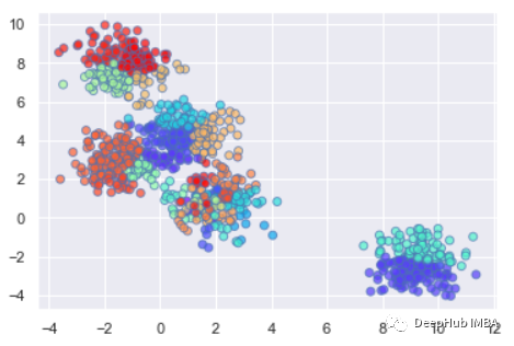
基于图的 Affinity Propagation 聚类计算公式详解和代码示例

渗透工具-TrustedSec 公司的渗透测试框架 (PTF)
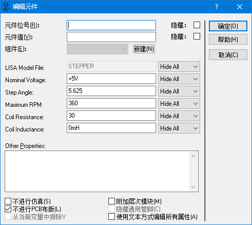
Arduino stepper library drive 28byj-48 stepper motor test program
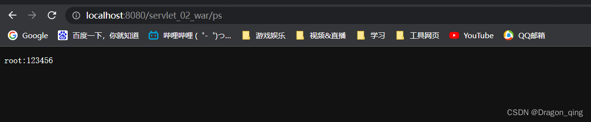
Servlet knowledge points
随机推荐
Tensorflow reports an error, could not load dynamic library 'libcudnn so. eight
Bind this of the current scope for callback functions in other cases such as timers and delayers
Oracle physical architecture
Sum the amount
P2433 [deep foundation 1-2] primary school mathematics n in one
math_利用微分算近似值
qobject_cast用法
关于元宇宙下一代入口——脑机接口的实现
振弦采集模塊測量振弦傳感器的流程步驟
HLS4ML报错The board_part definition was not found for tul.com.tw:pynq-z2:part0:1.0.
[research materials] Huawei Technology ICT 2021: at the beginning of the "Yuan" year, the industry is "new" -- download attached
Interview questions shared in today's group
Anaconda安装虚拟环境到指定路径
JS ternary expression complex condition judgment
Understand the structure in C language in one article
Procédure de mesure du capteur d'accord vibrant par le module d'acquisition d'accord vibrant
Object creation
[untitled]
数据分析师听起来很高大上?了解这几点你再决定是否转型
ModSim基本使用(Modbus模拟器)