当前位置:网站首页>HCIA experiment (07) comprehensive experiment
HCIA experiment (07) comprehensive experiment
2022-07-25 11:07:00 【Rainy days_】

【1】 The first stage : Basic configuration
1. Carry out topology design and address planning
192.168.1.0/24 ( Divided into three subnets , A backbone ,R1 and R2 Two subnets are required )
192.168.1.0/26 ( The backbone )
192.168.1.0/30
192.168.1.4/30 192.168.1.8/30 ...... 192.168.1.60/30
192.168.1.64/26 R1 192.168.1.64/27 192.168.1.96/27
192.168.1.128/26 R2 192.168.1.128/27 192.168.1.160/27
192.168.1.192/26

2. Configuring the router interface IP Address and sub interface
[r1]int g0/0/0
[r1-GigabitEthernet0/0/0]ip add 192.168.1.1 30
[r1]int g0/0/1.1
[r1-GigabitEthernet0/0/1.1]dot1q termination vid 2
[r1-GigabitEthernet0/0/1.1]arp broadcast enable
[r1-GigabitEthernet0/0/1.1]ip add 192.168.1.65 27
[r1]int g0/0/1.2
[r1-GigabitEthernet0/0/1.2]dot1q termination vid 3
[r1-GigabitEthernet0/0/1.2]arp broadcast enable
[r1-GigabitEthernet0/0/1.2]ip add 192.168.1.97 27
[r2]int g0/0/0
[r2-GigabitEthernet0/0/0]ip add 192.168.1.2 30
[r2]int g0/0/1
[r2-GigabitEthernet0/0/1]ip add 12.1.1.1 24
[r2]int g0/0/2.1
[r2-GigabitEthernet0/0/2.1]dot1q termination vid 2
[r2-GigabitEthernet0/0/2.1]arp broadcast enable
[r2-GigabitEthernet0/0/2.1]ip add 192.168.1.129 27
[r2]int g0/0/2.2
[r2-GigabitEthernet0/0/2.2]dot1q termination vid 3
[r2-GigabitEthernet0/0/2.2]arp broadcast enable
[r2-GigabitEthernet0/0/2.2]ip add 192.168.1.161 27
[r3]int g0/0/0
[r3-GigabitEthernet0/0/0]ip add 12.1.1.2 24
[r3]int g0/0/1
[r3-GigabitEthernet0/0/1]ip add 1.1.1.1 24
3. To configure DHCP service , Create a pond
[r1]ip pool v2
[r1-ip-pool-v2]network 192.168.1.64 mask 255.255.255.224
[r1-ip-pool-v2]gateway-list 192.168.1.65
[r1-ip-pool-v2]dns-list 114.114.114.114 8.8.8.8
[r1]ip pool v3
[r1-ip-pool-v3]network 192.168.1.96 mask 255.255.255.224
[r1-ip-pool-v3]gateway-list 192.168.1.97
[r1-ip-pool-v3]dns-list 114.114.114.114 8.8.8.8
[r1]int g0/0/1.1
[r1-GigabitEthernet0/0/1.1]dhcp select global
[r1]int g0/0/1.2
[r1-GigabitEthernet0/0/1.2]dhcp select global
[r2]ip pool v2
[r2-ip-pool-v2]network 192.168.1.128 mask 255.255.255.224
[r2-ip-pool-v2]gateway-list 192.168.1.129
[r2-ip-pool-v2]dns-list 114.114.114.114 8.8.8.8
[r2]ip pool v3
[r2-ip-pool-v3]network 192.168.1.160 mask 255.255.255.224
[r2-ip-pool-v3]gateway-list 192.168.1.161
[r2-ip-pool-v3]dns-list 114.114.114.114
[r2]int g0/0/2.1
[r2-GigabitEthernet0/0/2.1]dhcp select global
[r2]int g0/0/2.2
[r2-GigabitEthernet0/0/2.2]dhcp select global
4. Divide the interfaces on the switch into corresponding interfaces VLAN in
[sw1]vlan batch 2 to 3
[sw1]port-group group-member e0/0/2 to e0/0/3
[sw1-port-group]port link-type access
[sw1-port-group]port default vlan 2
[sw1]int e0/0/4
[sw1-Ethernet0/0/4]port link-type access
[sw1-Ethernet0/0/4]port default vlan 3
[sw2]vlan batch 2 to 3
[sw2]int e0/0/2
[sw2-Ethernet0/0/2]port link-type access
[sw2-Ethernet0/0/2]port default vlan 2
[sw2]int e0/0/3
[sw2-Ethernet0/0/3]port link-type access
[sw2-Ethernet0/0/3]port default vlan 3
5. To configure trunk main rd
[sw1]int e0/0/1
[sw1-Ethernet0/0/1]port link-type trunk
[sw1-Ethernet0/0/1]port trunk allow-pass vlan all
[sw2]int e0/0/1
[sw2-Ethernet0/0/1]port link-type trunk
[sw2-Ethernet0/0/1]port trunk allow-pass vlan all
6. Write for the server IP Address

7. test


【2】 The second stage : Divide the area
1. Declare
[r1]ospf 1 router-id 1.1.1.1
[r1-ospf-1]area 0
[r1-ospf-1-area-0.0.0.0]network 192.168.1.1 0.0.0.0
[r1-ospf-1]area 1
[r1-ospf-1-area-0.0.0.1]network 192.168.1.65 0.0.0.0
[r1-ospf-1-area-0.0.0.1]network 192.168.1.97 0.0.0.0
[r2]ospf 1 router-id 2.2.2.2
[r2-ospf-1]area 0
[r2-ospf-1-area-0.0.0.0]network 192.168.1.2 0.0.0.0
[r2-ospf-1]area 2
[r2-ospf-1-area-0.0.0.2]network 192.168.1.129 0.0.0.0
[r2-ospf-1-area-0.0.0.2]network 192.168.1.161 0.0.0.0
2. see


(R1 and R2 Established adjacency relationship between )
3. Optimize
[r1]ospf 1
[r1-ospf-1]area 1
[r1-ospf-1-area-0.0.0.1]abr-summary 192.168.1.64 255.255.255.192
[r2]ospf 1
[r2-ospf-1]area 2
[r2-ospf-1-area-0.0.0.2]abr-summary 192.168.1.128 255.255.255.192


( Interregional summary , Summarize the two loops into one loop )
4. Further optimization ( Block its hair Hello package )
Set silent interface
[r1]ospf 1
[r1-ospf-1]silent-interface g0/0/1.1
[r1-ospf-1]silent-interface g0/0/1.2
[r2]ospf 1
[r2-ospf-1]silent-interface g0/0/2.1
[r2-ospf-1]silent-interface g0/0/2.2
5. Perform encryption authentication
[r1]int g0/0/0
[r1-GigabitEthernet0/0/0]ospf authentication-mode md5 1 cipher 123456
[r2]int g0/0/0
[r2-GigabitEthernet0/0/0]ospf authentication-mode md5 1 cipher 123456
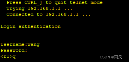
6. Turn on telnet function
[r1]aaa
[r1-aaa]local-user wang password cipher 123456
[r1-aaa]local-user wang service-type telnet
[r1-aaa]local-user wang privilege level 15
[r1-aaa]q
[r1]user-interface vty 0 4
[r1-ui-vty0-4]authentication-mode aaa
adopt DHCP obtain IP, There is a default route automatically

verification :

7. Refuse PC1 To three IP Of telnet Behavior
![]()
[r1] acl 3000
[r1-acl-adv-3000]
[r1-acl-adv-3000]rule deny tcp source 192.168.1.92 0 destination 192.168.1.1 0 destination-port eq 23
[r1-acl-adv-3000]rule deny tcp source 192.168.1.92 0 destination 192.168.1.65 0 destination-port eq 23
[r1-acl-adv-3000]rule deny tcp source 192.168.1.92 0 destination 192.168.1.97 0 destination-port eq 23
[r1]int g0/0/1.1
[r1-GigabitEthernet0/0/1.1]traffic-filter inbound acl 3000
verification :

【3】 The third stage : LAN access Wan
![]()
1. Build default routes
[r2]ospf 1
[r2-ospf-1]default-route-advertise always 
( by R1 Send the default route )
[r2]ip route-static 0.0.0.0 0 12.1.1.2( For the border router R2 Handwritten default route )
2. structure EASY NAT
[r2]acl 2000
[r2-acl-basic-2000]rule permit source 192.168.1.0 0.0.0.255
[r2-acl-basic-2000]q
[r2]int g0/0/1
[r2-GigabitEthernet0/0/1]nat outbound 2000
verification :

【4】 The fourth stage : Access through domain name HTTP
![]()
1. Set up servers and client


2. Port mapping
[r2]interface g0/0/1
[r2-GigabitEthernet0/0/1]nat server protocol tcp global current-interface 80 inside 192.168.1.100 80
Warning:The port 80 is well-known port. If you continue it may cause function failure.
Are you sure to continue?[Y/N]:y
3. verification

4. Set up port mapping
![]()
[r2]int g0/0/1
[r2-GigabitEthernet0/0/1]nat server protocol tcp global current-interface 23 inside 192.168.1.1 23
Warning:The port 23 is well-known port. If you continue it may cause function failure.
Are you sure to continue?[Y/N]:y
Successfully logged in :
5. Guard ring
[r1]ip route-static 192.168.1.0 26 NULL 0
[r2]ip route-static 192.168.1.128 26 null 0
边栏推荐
- Electromagnetic field and electromagnetic wave experiment I familiar with the application of MATLAB software in the field of electromagnetic field
- UE4 window control (maximize minimize)
- C3d model pytorch source code sentence by sentence analysis (I)
- Acquisition and compilation of UE4 source code
- HCIA实验(09)
- Reinforcement Learning 强化学习(四)
- Google Earth Engine——统计逐年土地分类的频率
- Nb-iot control LCD (date setting and reading)
- Digital twin everything can be seen | connecting the real world and digital space
- 基于cornerstone.js的dicom医学影像查看浏览功能
猜你喜欢

HCIP(13)

我为OpenHarmony 写代码,战“码”先锋第二期正式开启!

6. PXE combines kickstart principle and configuration to realize unattended automatic installation
From the perspective of open source, analyze the architecture design of SAP classic ERP that will not change in 30 years

JS hash table 01

Visual thematic map of American airport go style: ArcGIS Pro version

JS hash table 02

The most comprehensive UE4 file operation in history, including opening, reading, writing, adding, deleting, modifying and checking
I wrote code for openharmony, and the second phase of "code" pioneer officially opened!

Reinforcement Learning 强化学习(四)
随机推荐
C3d model pytorch source code sentence by sentence analysis (III)
UE4.26源码版学习广域网独立服务器时遇到的客户端运行黑屏问题
ONNX Runtime介绍
美国机场围棋风格可视化专题图:ArcGIS Pro版本
二合一的集度,任重道远
我为OpenHarmony 写代码,战“码”先锋第二期正式开启!
Openstack Skyline 组件安装
I wrote code for openharmony, and the second phase of "code" pioneer officially opened!
JS bidirectional linked list 02
Google Earth Engine——统计逐年土地分类的频率
Electromagnetic field and electromagnetic wave experiment I familiar with the application of MATLAB software in the field of electromagnetic field
BGP联邦实验
UE4 collision
How to optimize the performance when the interface traffic increases suddenly?
MySQL master-slave replication and read-write separation
C class library generation, use class library objects to data bind DataGridView
信号完整性(SI)电源完整性(PI)学习笔记(三十三)102条使信号完整性问题最小化的通用设计规则
Learn NLP with Transformer (Chapter 5)
Disabled and readonly and focus issues
我,AI博士生,在线众筹研究主题