当前位置:网站首页>Serial port experiment based on stm32f103zet6 library function
Serial port experiment based on stm32f103zet6 library function
2022-06-29 17:46:00 【It's Beichen bupiacra】
be based on STM32F103ZET6 Library function serial port experiment
This experiment realizes the following functions
STM32F1 Dialogue with the host computer through serial port ,STM32F1 After receiving the string sent by the upper computer , The original is returned to the upper computer .
Next, it mainly combines the description of registers from the operation level of library functions , Tell you how to set up the serial port , To achieve the most basic communication function . Using serial port 1 Keep printing information to the computer , At the same time, it receives the data sent from the serial port , Hair The data sent is directly sent back to the computer . adopt USB Serial port and computer communication .
The general steps of serial port setting can be summarized as follows
- Serial clock enable ,GPIO Clock enable
- Serial reset
- GPIO Port mode settings
- Initialization of serial port parameters
- Turn on interrupt and initialize NVIC( If you need to turn on interrupt, you need this step )
- Enable serial port
- Write interrupt handling functions
Several firmware library functions directly related to the basic configuration of the serial port
These functions and Definitions are mainly distributed in stm32f10x_usart.h and stm32f10x_usart.c In file .
1. Serial clock enable .
The serial port is attached to APB2 The following peripherals , So the enabling function is :
RCC_APB2PeriphClockCmd(RCC_APB2Periph_USART1);
2. Serial reset .
When the peripheral is abnormal, it can be set by reset , Reset the peripheral , And then reconfigure This peripheral achieves the purpose of making it work again . Generally, when the system starts to configure peripherals , Will be reset first Set operation . The reset is in the function USART_DeInit() Finish in :
void USART_DeInit(USART_TypeDef* USARTx);// Serial reset
3. Initialization of serial port parameters .
Serial port initialization is through USART_Init() Functionally implemented
void USART_Init(USART_TypeDef* USARTx, USART_InitTypeDef* USART_InitStruct);
The first entry parameter of this function is to specify the serial port label of initialization , Choose here USART1.
The second entry parameter is a USART_InitTypeDef Pointer to structure of type , The member variable of this structure pointer is used as To set some parameters of the serial port . The general implementation format is :
USART_InitStructure.USART_BaudRate = bound;                 						// Baud rate setting ;
USART_InitStructure.USART_WordLength = USART_WordLength_8b;							// The word is  8  Bit data format
USART_InitStructure.USART_StopBits = USART_StopBits_1;        						// A stop bit
USART_InitStructure.USART_Parity = USART_Parity_No;          						// No parity bit
USART_InitStructure.USART_HardwareFlowControl = USART_HardwareFlowControl_None;     // No hardware data flow control
USART_InitStructure.USART_Mode = USART_Mode_Rx | USART_Mode_Tx; 					// Transceiver mode
USART_Init(USART1, &USART_InitStructure);                   						// Initialize serial port
4… Data sending and receiving .
STM32 The data is sent and received through the data register USART_DR To achieve , This is a A double register , Contains TDR and RDR. When writing data to this register , The serial port will automatically send , When received When it comes to data , It also exists in this register .
STM32 Library function operation USART_DR The function of the register to send data is :
Through this function, the serial port register USART_DR Write a data .
void USART_SendData(USART_TypeDef* USARTx, uint16_t Data);
STM32 Library function operation USART_DR The function of the register to read the data received by the serial port is :
uint16_t USART_ReceiveData(USART_TypeDef* USARTx);
5. Serial port status .
In our firmware library function , The function to read the status of the serial port is :
FlagStatus USART_GetFlagStatus(USART_TypeDef* USARTx, uint16_t USART_FLAG);
The second entry parameter of this function is very critical , It indicates which state of the serial port we want to check , For example, as explained above RXNE( The read data register is not empty ) as well as TC( Send complete ).
For example, we need to determine whether the read register is not empty (RXNE), The way to manipulate library functions is :
USART_GetFlagStatus(USART1, USART_FLAG_RXNE);
We need to determine whether the transmission is complete (TC), The way to manipulate library functions is :
USART_GetFlagStatus(USART1, USART_FLAG_TC);
These identification numbers are MDK It is defined by macro :
#define USART_IT_PE ((uint16_t)0x0028)
#define USART_IT_TXE ((uint16_t)0x0727)
#define USART_IT_TC ((uint16_t)0x0626)
#define USART_IT_RXNE ((uint16_t)0x0525)
#define USART_IT_IDLE ((uint16_t)0x0424)
#define USART_IT_LBD ((uint16_t)0x0846)
#define USART_IT_CTS ((uint16_t)0x096A)
#define USART_IT_ERR ((uint16_t)0x0060)
#define USART_IT_ORE ((uint16_t)0x0360)
#define USART_IT_NE ((uint16_t)0x0260)
#define USART_IT_FE ((uint16_t)0x0160)
6. Serial port enable .
The serial port is enabled through the function USART_Cmd() To achieve
USART_Cmd(USART1, ENABLE); // Enable serial port
7. Open the serial port to respond to the interrupt .
Sometimes when we need to turn on the serial port interrupt , Then we also need to enable the serial port break , The function that enables serial port interrupt is :
void USART_ITConfig(USART_TypeDef* USARTx, uint16_t USART_IT, FunctionalState NewState);
The second entry parameter of this function is to indicate the type of enable serial port , That is, what kind of interrupt is enabled , Because the interrupt class of the serial port There are many types . For example, when receiving data (RXNE The read data register is not empty ), We need to generate interruptions , Then I The way we turn on interrupts is :
USART_ITConfig(USART1, USART_IT_RXNE, ENABLE);// Open interrupt , Received data interrupt
At the end of sending data (TC, Send complete ) To generate interrupts , So the way is :
USART_ITConfig(USART1,USART_IT_TC,ENABLE);
8. Get the corresponding interrupt status .
When we enable an interrupt , When the interrupt occurs , The status will be set A flag bit in memory . Often we are in the interrupt handler function , To determine what kind of interrupt the interrupt is , The function used is :
ITStatus USART_GetITStatus(USART_TypeDef* USARTx, uint16_t USART_IT)
For example, we enable the serial port sending completion interrupt , So when an interrupt occurs , We can call this in interrupt handling functions. A function to determine whether it is a serial port sending completion interrupt , The method is :
USART_GetITStatus(USART1, USART_IT_TC)
The return value is SET, It indicates that the serial port sending completion interrupt occurs .
Hardware design
1) Indicator light DS0
2) A serial port 1
Serial port used in this experiment 1 And USB The serial port is not in PCB Connected together , It needs to be connected through a jumper cap . Here we put P3 Of RXD and TXD Use jumper cap and PA9 and PA10 Connect .
software design
// initialization  IO  A serial port  1
void uart_init(u32 bound)
{

	GPIO_InitTypeDef GPIO_InitStructure;
	USART_InitTypeDef USART_InitStructure;
	NVIC_InitTypeDef NVIC_InitStructure;

	/*1. Can make USART1,GPIOA The clock */
	RCC_APB2PeriphClockCmd(RCC_APB2Periph_USART1|RCC_APB2Periph_GPIOA, ENABLE);

	/*2. Serial reset , Nothing here  */

	/*3.GPIO  Port mode settings  */
	//USART1_TX GPIOA.9
	GPIO_InitStructure.GPIO_Pin = GPIO_Pin_9; 					//PA.9
	GPIO_InitStructure.GPIO_Speed = GPIO_Speed_50MHz;
	GPIO_InitStructure.GPIO_Mode = GPIO_Mode_AF_PP;				// Multiplexing push pull output
	GPIO_Init(GPIOA, &GPIO_InitStructure);						// initialization GPIOA.9

	//USART1_RX GPIOA.10 initialization
	GPIO_InitStructure.GPIO_Pin = GPIO_Pin_10;					//PA10
	GPIO_InitStructure.GPIO_Mode = GPIO_Mode_IN_FLOATING;		// Floating input
	GPIO_Init(GPIOA, &GPIO_InitStructure);						// initialization GPIOA.10

	/*4. Initialization of serial port parameters  */
	//USART  Initialize settings
	USART_InitStructure.USART_BaudRate = bound;											// Serial port baud rate
	USART_InitStructure.USART_WordLength = USART_WordLength_8b;							// The word is 8 Bit data format
	USART_InitStructure.USART_StopBits = USART_StopBits_1;								// A stop bit
	USART_InitStructure.USART_Parity = USART_Parity_No;									// No parity bit
	USART_InitStructure.USART_HardwareFlowControl = USART_HardwareFlowControl_None;		// No hardware data flow control
	USART_InitStructure.USART_Mode = USART_Mode_Rx | USART_Mode_Tx;						// Transceiver mode
	USART_Init(USART1, &USART_InitStructure); 											// Initialize serial port 1

	/*5. initialization  NVIC */
	//Usart1 NVIC  To configure
	NVIC_InitStructure.NVIC_IRQChannel = USART1_IRQn;
	NVIC_InitStructure.NVIC_IRQChannelPreemptionPriority=3 ;							// preemption 3
	NVIC_InitStructure.NVIC_IRQChannelSubPriority = 3;									// Sub priority 3
	NVIC_InitStructure.NVIC_IRQChannelCmd = ENABLE;										//IRQ Channel enable
	NVIC_Init(&NVIC_InitStructure);														// Initialize... According to the specified parameters VIC register

	/*5. Open interrupt  */
	USART_ITConfig(USART1, USART_IT_RXNE, ENABLE);										// Open serial port to accept interrupt

	/*6. Enable serial port  */
	USART_Cmd(USART1, ENABLE);                    										// Enable serial port 1

}
① Serial clock enable ,GPIO Clock enable
② Serial reset
③ GPIO Port mode settings
④ Initialization of serial port parameters
⑤ initialization NVIC And turn on interrupt
⑥ Enable serial port
usart.c
#include "sys.h"
#include "usart.h"


// Support functions required by the standard library
struct __FILE
{

	int handle;
};
FILE __stdout;


// redefinition fputc function
int fputc(int ch, FILE *f)
{

	while((USART1->SR&0X40)==0)
	{

		;																			// Cycle to send , Until it's sent
	}
    USART1->DR = (u8) ch;
	return ch;
}


#if EN_USART1_RX // If enabled, receive

u8 USART_RX_BUF[USART_REC_LEN];     												// Receive buffer , Maximum USART_REC_LEN Bytes .

// Reception status
//bit15,  Receive completion flag
//bit14,  Received 0x0d
//bit13~0,  Number of valid bytes received
u16 USART_RX_STA=0;       															// Receive status flag

void uart_init(u32 bound)
{

	GPIO_InitTypeDef GPIO_InitStructure;
	USART_InitTypeDef USART_InitStructure;
	NVIC_InitTypeDef NVIC_InitStructure;

	RCC_APB2PeriphClockCmd(RCC_APB2Periph_USART1|RCC_APB2Periph_GPIOA, ENABLE);		// Can make USART1,GPIOA The clock

	/*USART1_TX GPIOA.9*/
	GPIO_InitStructure.GPIO_Pin = GPIO_Pin_9; 										//PA.9
	GPIO_InitStructure.GPIO_Speed = GPIO_Speed_50MHz;
	GPIO_InitStructure.GPIO_Mode = GPIO_Mode_AF_PP;									// Multiplexing push pull output
	GPIO_Init(GPIOA, &GPIO_InitStructure);											// initialization GPIOA.9

	/*USART1_RX GPIOA.10*/
	GPIO_InitStructure.GPIO_Pin = GPIO_Pin_10;										//PA.10
	GPIO_InitStructure.GPIO_Mode = GPIO_Mode_IN_FLOATING;							// Floating input
	GPIO_Init(GPIOA, &GPIO_InitStructure);											// initialization GPIOA.10

	//Usart1 NVIC  To configure
	NVIC_InitStructure.NVIC_IRQChannel = USART1_IRQn;
	NVIC_InitStructure.NVIC_IRQChannelPreemptionPriority=3 ;						// preemption 3
	NVIC_InitStructure.NVIC_IRQChannelSubPriority = 3;								// Sub priority 3
	NVIC_InitStructure.NVIC_IRQChannelCmd = ENABLE;									//IRQ Channel enable
	NVIC_Init(&NVIC_InitStructure);													// Initialize... According to the specified parameters VIC register

   //USART  Initialize settings
	USART_InitStructure.USART_BaudRate = bound;										// Serial port baud rate
	USART_InitStructure.USART_WordLength = USART_WordLength_8b;						// The word is 8 Bit data format
	USART_InitStructure.USART_StopBits = USART_StopBits_1;							// A stop bit
	USART_InitStructure.USART_Parity = USART_Parity_No;								// No parity bit
	USART_InitStructure.USART_HardwareFlowControl = USART_HardwareFlowControl_None; // No hardware data flow control
	USART_InitStructure.USART_Mode = USART_Mode_Rx | USART_Mode_Tx;					// Transceiver mode
	USART_Init(USART1, &USART_InitStructure); 										// Initialize serial port 1

	USART_ITConfig(USART1, USART_IT_RXNE, ENABLE);									// Open serial port receive interrupt
	USART_Cmd(USART1, ENABLE);                    									// Enable serial port 1

}

/* A serial port 1 Interrupt service routine */
void USART1_IRQHandler(void)
{

	u8 Res;
	if(USART_GetITStatus(USART1, USART_IT_RXNE) != RESET)  							// Receive interrupt ( The data received must be 0x0d 0x0a ending )
	{

		Res =USART_ReceiveData(USART1);												// Read received data

		if((USART_RX_STA&0x8000)==0)												// Reception is not complete
		{

			if(USART_RX_STA&0x4000)													// received 0x0d
			{

				if(Res!=0x0a)
				{

					USART_RX_STA=0;													// Receive error , restart
				}
				else
				{

					USART_RX_STA|=0x8000;											// The reception is complete
				}
			}
			else 																	// I haven't received 0x0d
			{

				if(Res==0x0d)
				{

					USART_RX_STA|=0x4000;
				}
				else
				{

					USART_RX_BUF[USART_RX_STA&0X3FFF]=Res;
					USART_RX_STA++;
					if(USART_RX_STA>(USART_REC_LEN-1))
					{

						USART_RX_STA=0;												// Receiving data error , Start receiving again
					}
				}
			}
		}
    }
}
#endif
If EN_USART1_RX be equal to 1 The following code executes
Define buffer and receive status flags , Receive marked as 16 position
0 To 13 Bits are the number of valid received
14 Bit is received 0x0d The tag
15 Bit is received 0x0a The tag ( That is, the reception is completed )
Just follow the steps to configure the serial port initialization
Let's talk about the serial port 1 The interrupt service function of 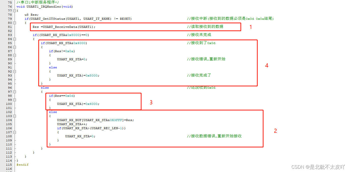
The first step is to read the received data and save it to Res( Here is 8 position , Every time 8 Bit receive once )
Step 2 if you haven't read 0x0d Just put it in the buffer USART_RX_BUF[USART_RX_STA&0X3FFF]=Res;
USART_RX_STA&0X3FFF, The restriction here only applies to 0 To 13 position
if(USART_RX_STA>(USART_REC_LEN-1)) This also limits the size of the buffer
Step 3 if you read 0x0d Just change 14 Bit status USART_RX_STA|=0x4000; Give Way 14 Location 1
Step 4 receive 0x0d The next one is to judge whether it is 0x0a, If so, change 15 Bit status USART_RX_STA|=0x8000; Give Way 15 Location 1, That is, the reception is completed
There is also a redirection function int fputc(int ch, FILE *f)
This function was originally to convert the character ch Print to file pointer stream The file stream pointed to , We don't need to print the file stream now , But print to serial port 1
usart.h
#ifndef __USART_H
#define __USART_H
#include "stdio.h"
#include "sys.h"

#define USART_REC_LEN 200 // Define the maximum number of bytes received  200
#define EN_USART1_RX 1 // Can make (1)/ prohibit (0) A serial port 1 receive

extern u8  USART_RX_BUF[USART_REC_LEN]; // Receive buffer , Maximum USART_REC_LEN Bytes . The last byte is a newline character
extern u16 USART_RX_STA;         		// Receive status flag

void uart_init(u32 bound);
#endif
extern u8 USART_RX_BUF[USART_REC_LEN]; // Receive buffer , Maximum USART_REC_LEN Bytes . The last byte is a newline character
extern u16 USART_RX_STA; // Receive status flag
extern Declare to use these variables for other files
main.c
#include "led.h"
#include "delay.h"
#include "key.h"
#include "sys.h"
#include "usart.h"


int main(void)
{

	u16 t;
	u16 len;
	u16 times=0;
	delay_init();	    	 																	// Delay function initialization
	NVIC_PriorityGroupConfig(NVIC_PriorityGroup_2); 											// Set up NVIC Interrupt grouping 2:2 Bit preemption priority ,2 Bit response priority
	uart_init(115200);	 																		// The serial port is initialized to 115200
 	LED_Init();			     																	//LED Port initialization
	KEY_Init();          																		// Initialize the hardware interface connected with the key

	while(1)
	{

		if(USART_RX_STA&0x8000)
		{

			len=USART_RX_STA&0x3fff;															// The length of data received this time
			printf("\r\n The message you sent is :\r\n\r\n");
			for(t=0;t<len;t++)
			{

				USART_SendData(USART1, USART_RX_BUF[t]);										// Serial port 1 send data
				while(USART_GetFlagStatus(USART1,USART_FLAG_TC)!=SET);							// Wait for the end of sending
			}
			printf("\r\n\r\n");																	// Insert newline
			USART_RX_STA=0;
		}
		else
		{

			times++;
			if(times%5000==0)
			{

				printf("\r\n Serial port experiment \r\n");
				printf(" It's Beibu bupia \r\n\r\n");
			}
			if(times%200==0)
			{

				printf(" Please input data , End with enter , Or check send new line \r\n");
			}
			if(times%30==0)
			{

				LED0=!LED0;																		// flashing LED, Indicates that the system is running .
			}
			delay_ms(10);
		}
	}
}
if(USART_RX_STA&0x8000) Determine whether the reception is complete
If the reception is completed, send the data back
USART_RX_STA Is the actual number of bytes transmitted
len=USART_RX_STA&0x3fff; Here is the 14,15 The flag bit of bit is removed
边栏推荐
- How MySQL queries character set codes of tables
- 面试中问最常问的海量数据处理你拿捏了没?
- 力扣今日题-535. TinyURL 的加密与解密
- selenium上传文件
- 双亲委派机制
- Inherit Chinese virtues, pay attention to the health of the middle-aged and the elderly, and Yurun milk powder has strong respect for the elderly
- MATLAB 最远点采样(FPS)
- R language uses user-defined functions to write deep learning leaky relu activation functions and visualize leaky relu activation functions
- What is the SRM system? How do I apply the SRM system?
- R语言使用自定义函数编写深度学习线性激活函数、并可视化线性激活函数
猜你喜欢


![分割回文串[dp + dfs组合]](/img/7b/221b000984977508f849e19802c2c2.png)


随机推荐
Repair of JSON parsing errors in a collection
上班可以做副业
R language ggplot2 visualization: use the patchwork package (directly use the plus sign +) to horizontally combine the two ggplot2 visualization results, and then horizontally combine them with the th
自定義HandlerInterceptor攔截器實現用戶鑒權
Segment tree and tree array template (copy and paste are really easy to use)
阿里云不同账号新旧服务器镜像迁移数据迁移同步
ISO 32000-2 international standard 7.7
selenium 文件上传方法
[webdriver] upload files using AutoIT
DevCloud加持下的青软,让教育“智”上云端
Split palindrome string [dp + DFS combination]
mysql在linux中2003错误如何解决
R语言使用MASS包的glm.nb函数建立负二项广义线性模型(negative binomial)、summary函数获取负二项广义线性模型模型汇总统计信息
自定义HandlerInterceptor拦截器实现用户鉴权
MATLAB 最远点采样(FPS)
Createstore for Redux source code analysis
两种Controller层接口鉴权方式
The dplyr package filter function of R language filters the data in dataframe data through combinatorial logic (and logic). The content of one field is equal to one of the specified vectors, and the v
R language ggplot2 visualization: use the patchwork package (directly use the plus sign +) to horizontally combine a ggplot2 visualization result and a plot function visualization result to form the f
分割回文串[dp + dfs组合]