当前位置:网站首页>Lesson 4 serial port and clock
Lesson 4 serial port and clock
2022-06-26 05:26:00 【Super cute sandwich kids】
1.CC2530 During normal operation, a high-frequency clock signal and a low-frequency clock signal are required
High frequency clock signals are mainly supplied to CPU Make sure the program runs ; The low-frequency clock signal is mainly supplied to the watchdog 、 Sleep timer and other on-chip peripherals .
2. The source of the clock signal
High frequency clock signal has 2 individual , Internal to the chip 16M RC ; disjunctive 32M Quartz crystal oscillator (2 Choose one of them to supply CPU)
Low frequency clock signal has 2 individual , Internal to the chip 32K RC ; disjunctive 32.768K Quartz crystal oscillator (2 Choose one of them for the watchdog 、 Sleep timer and other on-chip peripherals )
3.CC2530 When the chip is powered on by default , It's internal 2 individual RC The circuit is used as the clock source of high frequency and low frequency .
4. If we're using a serial port , Especially when wireless communication , It must be used. 32M Quartz crystal oscillator as the source of high-frequency clock .
5. Characteristics of high frequency clock :2 A high-frequency clock source can vibrate at the same time to generate a high-frequency clock signal ; and 2 Only one low-frequency clock source can vibrate at a time , And the starting clock source supplies CC2530.
System high frequency clock switching steps :( from 16M RC Switch to 32M )
1. Give Way 2 A high-frequency clock source vibrates
2. Wait for the target clock source to vibrate and stabilize
3. Delay for a short time 63us
4. No frequency division output Regardless of the frequency 32M, Dichotomy 16M,
5. Select the target high frequency clock source as the system master clock source
6. Confirm whether the current working system clock is the selected high-frequency clock
SLEEPCMD 、SLEEPSTA 、CLKCONCMD 、CLKCONSTA ,CMD: Write register ,STA: Status register
1. Give Way SLEEPCMD The first 2 Position as 0
2. Give Way SLEEPSTA The first of the registers 6 Position as 1, Express 32M The clock source is stable
3. exceed 63us Time delay
4. Put the register CLKCONCMD It's low 3 Bit is set to 000, Indicates no frequency division output
5. Put the register CLKCONCMD Of the 6 Positional clarity 0, Set to 32M As the system master clock ( If you put 1 It is 16M)
6 If you read CLKCONSTA The number of this register is 6 Position as 0, Express 32M The clock source of has been used as the master clock of the system , The system can continue to run .( Inspection function )
Example 1: Let the nixie tube show 0-9,16M Output
#include<iocc2530>
#include"74LS164_8LED.h"
void delay()
{
int i,j;
for(i=0;i<1000;i++)
for(j=0;j<800;j++)
}
void main()
{
char i;
LS164_Cfg();// initialization
while(1)
{
for(i=0;i<10;i++)
{
LS164_BYTE(i);// The nixie tube displays from 0 To 9
delay();// The time delay function
}
}
}
Example 2: Let the nixie tube show 0-9,32M Output
#include<iocc2530>
#include"74LS164_8LED.h"
void delayus()
{
char k=63;
while(k--);
}
void delay()
{
int i,j;
for(i=0;i<1000;i++)
for(j=0;j<800;j++)
}
void Init32M()
{
SEELPCMD &=0xFB; //1111 1011 Turn on 2 A high frequency clock source
while(SLEEPSTA &0x40);// 0100 0000 wait for 32M Stable
delayus();// Time delay 63u function
CLKCONCMD &=0xF8;//1111 1000 No frequency division output
CLKCONCMD &=0xBF;//1011 1111 Set up 32M Master clock
while(CLKCONSTA &0x40);//0100 0000 wait for 32M Successfully become the master clock of the current system
}
void main()
{
char i;
LS164_Cfg();// initialization
while(1)
{
for(i=0;i<10;i++)
{
LS164_BYTE(i);// The nixie tube displays from 0 To 9
delay();// The time delay function
}
}
}
Master the switching of the clock 、 Control serial port
CC2530 have 2 A serial port , And each serial port can be configured with a selection control pin
Configuration of serial port position :
1. Specify the serial port IO Location ; Alternate position 1 Alternate position 2
2. The corresponding IO Configure on-chip peripheral functions ;
3.8 Data bits 、1 Stop bits 、 No flow control 、 No verification established .
4. Baud rate ;
5. open CPU interrupt 、 Corresponding serial port receiving interrupt ;
#include<iocc2530.h>
void Init32M()
{
SEELPCMD &=0xFB; //1111 1011 Turn on 2 A high frequency clock source
while(SLEEPSTA &0x40);// 0100 0000 wait for 32M Stable
delayus();// Time delay 63u function
CLKCONCMD &=0xF8;//1111 1000 No frequency division output
CLKCONCMD &=0xBF;//1011 1111 Set up 32M Master clock
while(CLKCONSTA &0x40);//0100 0000 wait for 32M Successfully become the master clock of the current system
}
void UartCfg()
{// A serial port 0 Your spare location 1 Configure baud rate 9600
PERCFG &=0xF1;//1111 0001 Select serial port 0 Your spare location 1;
P0SEL |=0x0C;//0000 1100 P0_2 P0_3 For on-chip peripheral functions
U0CSR |=0xC0;//
U0GCR =8;
U0BAUD =59;
EA=1; // Open total interrupt
URX0IE=1;
}
void main()
{
Init32M();
UartCfg();
while(1);
}
#pragma vector=URX0_VECTOR
__interrupt void URX0_IR0(void)
{
char ch;
URX0IF=0;// Serial port data bit flag , The hardware will be set 1, Software clearance 0
ch=U0DBUF;// Take bytes from the receiving register and store them in ch
U0DBUF=ch;// Put variables ch The value in is assigned to the sending serial port 0 Send register
while(UTX0IF==0);
UTX0IF=0;
}
边栏推荐
- Henkel database custom operator '~~‘
- 瀚高数据库自定义操作符‘!~~‘
- PHP 2D / multidimensional arrays are sorted in ascending and descending order according to the specified key values
- Douban top250
- 二次bootloader关于boot28.asm应用的注意事项,28035的
- 基于SDN的DDoS攻击缓解
- Lstms in tensorflow_ Cell actual combat
- Red team scoring method statistics
- The wechat team disclosed that the wechat interface is stuck with a super bug "15..." The context of
- 2021年OWASP-TOP10
猜你喜欢

红队得分方法统计

Beidou navigation technology and industrial application of "chasing dreams in space and feeling for Beidou"

Replacing domestic image sources in openwrt for soft routing (take Alibaba cloud as an example)

Setting pseudo static under fastadmin Apache
Classic theory: detailed explanation of three handshakes and four waves of TCP protocol
FastAdmin Apache下设置伪静态

慢慢学JVM之缓存行和伪共享

Practical cases | getting started and mastering tkinter+pyinstaller

cartographer_fast_correlative_scan_matcher_2d分支定界粗匹配
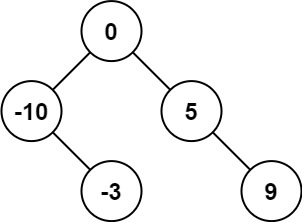
LeetCode_二叉搜索树_简单_108.将有序数组转换为二叉搜索树
随机推荐
The difference between get and post in small interview questions
LeetCode_ Binary search tree_ Simple_ 108. convert an ordered array to a binary search tree
Introduction to alluxio
国务院发文,完善身份认证、电子印章等应用,加强数字政府建设
The parameter field of the callback address of the payment interface is "notify_url", and an error occurs after encoding and decoding the signed special character URL (,,,,,)
The localstorage browser stores locally to limit the number of forms submitted when tourists do not log in.
Windows下安装Tp6.0框架,图文。Thinkphp6.0安装教程
cartographer_ optimization_ problem_ 2d
Daily production training report (16)
SSH connected to win10 and reported an error: permission denied (publickey, keyboard interactive)
百度API地图的标注不是居中显示,而是显示在左上角是怎么回事?已解决!
【MYSQL】MySQL 百万级数据量分页查询方法及其优化
ZigBee explain in simple terms lesson 2 hardware related and IO operation
How to select the data transmission format of instant messaging application
Positioning setting horizontal and vertical center (multiple methods)
Lstms in tensorflow_ Cell actual combat
Daily production training report (15)
zencart新建的URL怎么重写伪静态
PHP 2D / multidimensional arrays are sorted in ascending and descending order according to the specified key values
Serious hazard warning! Log4j execution vulnerability is exposed!