当前位置:网站首页>Single chip microcomputer: pcf8591 application program
Single chip microcomputer: pcf8591 application program
2022-06-13 03:53:00 【DC-STDIO】
List of articles
PCF8591 Applications
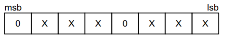
PCF8591 The communication interface is I2C, Then programming must comply with this protocol . Single chip microcomputer is right PCF8591 To initialize , Send a total of three bytes . First byte , and EEPROM similar , Is the device address byte , among 7 Bits represent the address ,1 Bits represent the reading and writing direction . Address high 4 The fixed position is 0b1001, The lower three are A2,A1,A0, All three of us are connected to the circuit GND, So that is 0b000, As shown in the figure .
Send to PCF8591 The second byte of will be stored in the control register , Used to control the PCF8591 The function of . Among them the first 3 Position and number 7 The bit is fixed 0, in addition 6 Each bit has its own role , As shown in the figure below , Senior students will introduce one by one .
The... Of the control byte 6 Is it DA Enable bit , This position 1 Express DA Output pin enable , Will produce analog voltage output function . The first 4 Position and number 5 Bit can realize PCF8591 Of 4 Analog inputs are configured into single ended mode and differential mode , The difference between single ended mode and differential mode , We have introduced it in previous articles , Here you only need to know that these two are configuration AD Enter the control bit of the mode .

The... Of the control byte 2 Bit is the automatic increment control bit , Automatic increment means , For example, we have 4 Channels , When we use it all , After reading the passage 0, Read it again next time , Will automatically enter the channel 1 To read , We don't need to specify the next channel , because A/D Every time I read the data , Are the results of the last conversion , So when students use the automatic increment function , Pay special attention to , What you are currently reading is the value of the previous channel . In order to maintain the universality of the program , Our code doesn't use this function , Directly made a general program .
The... Of the control byte 0 Position and number 1 Bit is the channel selection bit ,00、01、10、11 Represents the 0 To 3 Of 4 A channel selection .
Send to PCF8591 The third byte of D/A Data register , Express D/A Voltage value of analog output .D/A Let's introduce , You know the function of this byte . If we just use A/D Function words , You can not send the third byte .
Let's use a program , hold AIN0、AIN1、AIN3 The measured voltage value is displayed on the LCD , At the same time, you can turn the potentiometer , Will find AIN0 The value of has changed . /Lcd1602.c File program source code **/ ( Omit here , Refer to the code in the previous chapter ) /I2C.c File program source code **/
/*****************************main.c  File program source code ******************************/
#include <reg52.h>
bit flag300ms = 1; //300ms  Timing mark
unsigned char T0RH = 0; //T0  High byte of overloaded value
unsigned char T0RL = 0; //T0  The low byte of the overloaded value

void ConfigTimer0(unsigned int ms);
unsigned char GetADCValue(unsigned char chn);
void ValueToString(unsigned char *str, unsigned char val);
extern void I2CStart();
extern void I2CStop();
extern unsigned char I2CReadACK();
extern unsigned char I2CReadNAK();
extern bit I2CWrite(unsigned char dat);
extern void InitLcd1602();
extern void LcdShowStr(unsigned char x, unsigned char y, unsigned char *str);

void main(){

    unsigned char val;
    unsigned char str[10];

    EA = 1; // General interruption
    ConfigTimer0(10); // To configure  T0  timing  10ms
    InitLcd1602(); // Initialize the LCD
    LcdShowStr(0, 0, "AIN0 AIN1 AIN3"); // Display channel indication

    while (1){

        if (flag300ms){

            flag300ms = 0; // Display channel  0  The voltage of
            val = GetADCValue(0); // obtain  ADC  passageway  0  The conversion value of
            ValueToString(str, val); // Voltage value converted to string format
            LcdShowStr(0, 1, str); // Display on the LCD
            // Display channel  1  The voltage of
            val = GetADCValue(1);
            ValueToString(str, val);
            LcdShowStr(6, 1, str);
            // Display channel  3  The voltage of
            val = GetADCValue(3);
            ValueToString(str, val);
            LcdShowStr(12, 1, str);
        }
    }
}
/*  Read the current  ADC  Conversion value ,chn-ADC  Channel number  0~3 */
unsigned char GetADCValue(unsigned char chn){

    unsigned char val;
    I2CStart();
    if (!I2CWrite(0x48<<1)){
     // Addressing  PCF8591, If not answered , Stop the operation and return to  0
        I2CStop();
        return 0;
    }
    I2CWrite(0x40|chn); // Write control byte , Select the conversion channel
    I2CStart();
    I2CWrite((0x48<<1)|0x01); // Addressing  PCF8591, Specifies the subsequent read operation
    I2CReadACK(); // Read a byte empty first , Provide sample conversion time
    val = I2CReadNAK(); // Read the value just converted
    I2CStop();
    return val;
}
/* ADC  Convert the value to the string form of the actual voltage value ,str- String pointer ,val-AD  Conversion value  */
void ValueToString(unsigned char *str, unsigned char val){

    // Voltage value = Conversion result *2.5V/255, Type in the  25  Implied one decimal decimal
    val = (val*25) / 255;
    str[0] = (val/10) + '0'; // Integer bit character
    str[1] = '.'; // decimal point
    str[2] = (val%10) + '0'; // Decimal characters
    str[3] = 'V'; // Voltage unit
    str[4] = '\0'; // Terminator
}
/*  Configure and start  T0,ms-T0  Timing time  */
void ConfigTimer0(unsigned int ms){

    unsigned long tmp; // Temporary variable
    tmp = 11059200 / 12; // The timer counts the frequency
    tmp = (tmp * ms) / 1000; // Calculate the required count
    tmp = 65536 - tmp; // Calculate timer overload value
    tmp = tmp + 12; // Compensate for the error caused by interrupt response delay
    T0RH = (unsigned char)(tmp>>8); // The timer overload value is split into high and low bytes
    T0RL = (unsigned char)tmp;
    TMOD &= 0xF0; // Zero clearing  T0  Control bit of
    TMOD |= 0x01; // To configure  T0  For mode  1
    TH0 = T0RH; // load  T0  Overload value
    TL0 = T0RL;
    ET0 = 1; // Can make  T0  interrupt
    TR0 = 1; // start-up  T0
}
/* T0  Interrupt service function , perform  300ms  timing  */
void InterruptTimer0() interrupt 1{

    static unsigned char tmr300ms = 0;
    TH0 = T0RH; // Reload overloaded values
    TL0 = T0RL;
    tmr300ms++;
    if (tmr300ms >= 30){
     // timing  300ms
        tmr300ms = 0;
        flag300ms = 1;
    }
}
Students who read the program carefully will find , The program is in progress A/D When reading data , Two programs were used to read 2 Bytes :I2CReadACK(); val = I2CReadNAK(); PCF8591 The conversion clock of is I2C Of SCL,8 individual SCL Cycle completes a conversion , So the current conversion result is always in the next byte 8 individual SCL Can only be read on , So the function of our first statement here is to produce a whole SCL Clock supplied to PCF8591 Conduct A/D transformation , The second time is to read the current conversion result . If we only use the second statement , Every time I read the result of the last conversion .
边栏推荐
猜你喜欢
![[note]vs2015 compilation of masm32 using MASM32 Library](/img/f5/b47336af248d1b485208ec3f9ca12b.png)
[note]vs2015 compilation of masm32 using MASM32 Library

【测试开发】自动化测试selenium(三)——unittest框架解析

单片机:红外遥控通信原理

leetcode.1 --- 两数之和

GoFrame第四天

单片机信号发生器程序

Watering artifact based on Huawei cloud Internet of things (stm32+esp8266)

Wechat payment configuration
[笔记]vs2015 编写汇编masm32之使用MASM32库

LVS four layer load balancing cluster (5) LVS overview
随机推荐
MySQL 8.0 enables remote root user access and solves the problem of you are not allowed to create a user with Grant
[test development] automated test selenium (III) -- unittest framework analysis
5G China unicom AP:B SMS ASCII 转码要求
Lambda end operation find and match findany
Real time requirements for 5g China Unicom repeater network management protocol
Synching build your own synchronization cloud
Lambda end operation count
H5 jump to mobile app store
【愚公系列】2022年06月 .NET架构班 080-分布式中间件 ScheduleMaster的Master集群和数据库切换
Ego planner code analysis ----cmakelists Txt and package xml
Among the four common technologies for UAV obstacle avoidance, why does Dajiang prefer binocular vision
【Web】Cookie 和 Session
Jumpserver: user - system privileged user - Asset - authorization
Determine whether the file encoding format is UTF-8 or GBK
Lambda终结操作查找与匹配findFirst
Big Five personality learning records
【愚公系列】2022年06月 .NET架构班 081-分布式中间件 ScheduleMaster的API自定义任务
5g China Unicom ap:b SMS ASCII transcoding requirements
Installing MySQL 8.0.20 under Linux and ubuntu20.04 LTS
单片机/嵌入式的实时性疑问解答