当前位置:网站首页>Model electricity experiment -- Experiment 2 JFET common source amplifier circuit
Model electricity experiment -- Experiment 2 JFET common source amplifier circuit
2022-06-22 07:49:00 【Amorous scholar】
Catalog
3、 ... and 、 Experimental principle
1、 Experimental simulation circuit
2、 Characteristics and parameters of Junction FET
3、 Performance analysis of FET amplifier
4、 Measurement method of input resistance
2、 Measurement and adjustment of static working point
3、 Voltage amplification Av、 Input resistance Ri And output resistance Ro The measurement of
One 、 The experiment purpose
- Understand the performance and characteristics of Junction FET .
- Be more familiar with the test method of amplifier dynamic parameters .
Two 、 Experimental apparatus
- Dual trace oscilloscope
- A multimeter
- AC millivoltmeter
- Signal generator
3、 ... and 、 Experimental principle
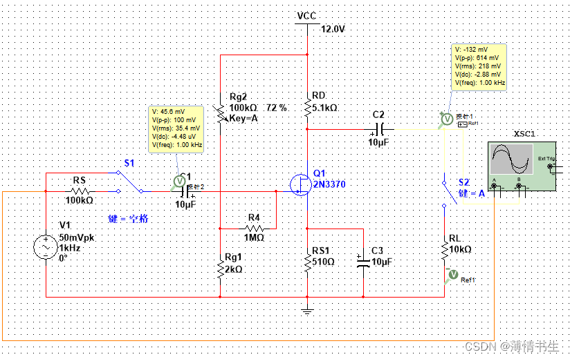
1、 Experimental simulation circuit

chart 1 Junction FET common source amplifier
2、 Characteristics and parameters of Junction FET
The ideal model is selected in the simulation experiment N Ditch JFET

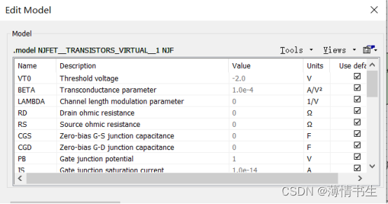
This experiment , Focus on the first three parameters of the tube , first VTO=-2V, namely JFET Pinch off voltage Vp or VGS(off), the second BETA=0.1m A/V2, namely JFET Conductance constant of Kn, Third LAMBDA=0, That is, the channel length modulation effect is not considered .
3、 Performance analysis of FET amplifier
chart 1 It is a common source amplifier circuit composed of Junction FET . The static working point of the theoretical calculation value is as follows :(Rg2=72k)
UGS=UG-Us=(Rg1/(Rg1+Rg2))*UCC-ID*RS1
ID=IDSS*(1- UGS/UP)^2 ,IDSS=Kn*VP^2
The above formula is simultaneous , Obtainable UGSQ=100mv,IDQ=441u A ,UDSQ= UCC-IDQ(RS1+RD)=9.56V
UGSQ> Vp, And UDSQ>UGSQ-VP, Therefore, the pipe works in the saturation zone . The static working point is not adjusted later , On this basis, AC parameter values are calculated .
gm=2kn*(UGSQ-Vp=2*0.1*(100mv -(-2))=0.42ms
If voltage amplification factor Av=-gm*RL'=-gm*(RD║RL)=-0.42*(5.1k//10k)=-1.42
Input resistance Ri=RG+(Rg1║Rg2)=RG=1MΩ( a little bigger than )
Output resistance Ro≈RD=5.1kΩ
4、 Measurement method of input resistance
Static operating point of FET amplifier 、 Measurement method of voltage magnification and output resistance , The measurement method is the same as that of the transistor amplifier in Experiment 1 . Measurement of its input resistance , In principle , The method described in Experiment 1 can also be used , But due to the Ri The larger , Such as direct measurement of input voltage Us and Ui, Because the input resistance of the measuring instrument is limited , It will inevitably bring about large errors ( There is generally no such concern in the simulation ). So in order to reduce the error , Always use the isolation function of the amplifier under test , By measuring the output voltage Uo To calculate the input resistance . The measuring circuit is shown in the figure 2 Shown .

Put a resistor in series at the input end of the amplifier R, Switch K Throw to position 1( Even if R=0), Measure the input voltage of the amplifier Uo1=Av*Us; keep Us unchanged , And then K Throw direction 2( Namely access R), Measure the output voltage of the amplifier Uo2. Since two measurements Av and Us remain unchanged , so Uo2=Av*Ui=(Ri/R+Ri)*Us*Av. From this we can find Ri=Uo2/(Uo1-Uo2) *R, In style R and Ri Don't make a big difference , This simulation experiment can be R=100KΩ.
Four 、 Experimental content
1、 According to the figure 1 Expand the connection , And make the potentiometer Rg1 The initial value is adjusted to 72K
2、 Measurement and adjustment of static working point
According to the figure 1 Operation measurement data of , Measure the value of the static working point , And fill in the following table .


3、 Voltage amplification Av、 Input resistance Ri And output resistance Ro The measurement of
(1)Av and Ro The measurement of
According to the plan 1 Circuit experiment , hold RD The value is fixed at 5.1K Access circuit , Add a frequency of... At the input of the amplifier 1KHz、 The peak to peak is 100mV The sine signal of Ui, Not yet Rs, And monitor the output with an oscilloscope Uo Waveform of . At output Uo Without distortion , Measure separately RL=∞ and RL=10KΩ The output voltage of Uo( Be careful : keep Ui unchanged ), Record in table 4-2.


(2)Ri The measurement of
According to the figure 2 Connect the experimental circuit , hold RD The value is fixed at 5.1K Access circuit , The selection frequency is 1KHz、 The peak to peak is 100mV Sinusoidal signal input voltage Us, Turn the switch on K Throw direction “1”, measure Rs=0 Output voltage at Uo1, Then throw the switch to “2”( Access Rs), keep Us unchanged , Then measure Uo2, According to the formula (Uo2/(Uo1-UOo2))*Rs, Find out Ri, Record in table 4-3.(RL=∞, Each voltage is measured and calculated using peak to peak values )

边栏推荐
- Open source get through version - integral function
- Wechat games (2)
- Xmind 2022思维导图激活版资源?
- Fmdb usage details mark
- Major enterprises are losing money one after another. Where will the environmental protection industry go?
- 网站如何提高百度权重
- 8、 Slider assembly
- 数据可视化优秀案例
- phpcms手机门户网站配置
- Wx applet vant UI call interface to realize two-level cascade
猜你喜欢

Detailed explanation of subnet mask

How to backup the treasures in the store and upload them to multiple stores

代码覆盖率测试对编程小白的意义及其使用方法

Problems caused by canvas palette width and height and canvas width and height

The applet uses the step bar vant steps in vant

Applet /vant UI to upload files

How to authorize a picture in a store to another store? What are the methods of unauthorized replication

Excellent cases of data visualization
How to cancel crmeb customer service link

Get through version 4.3 mind map
随机推荐
Unity AssetBundle packaging
Applet vant UI implementation calls interface data and displays it
FFMPEG坑
Usage and understanding of async/await in JS
Does it matter if you delete the pictures in the picture space after uploading to the store
Target detection series -- detailed explanation of RCNN principle
Baidu Post Bar crawler crawls to the middle of the building
Get through version - bargain activity
7、 Picker component
mysql查询group by 1055 问题完美解决,最简单最便捷的方法
Vue failed to connect to MySQL database
Introduction to several mainstream and easy-to-use rich text editors (WYSIWYG common editors)
5、 Image component
Solve syntaxerror: cannot use import statement outside a module
Backup the method of uploading babies in Taobao stores to multiple stores
How to improve Baidu's weight
vue连接mysql数据库失败
mysql截取字符串CS0000_1中_后面的字符
Layer drawing method
Technology blog collection